

TL;DR #
If you’re evaluating a multi-pack residential BESS for procurement and your supplier hasn’t addressed light-load standby loss at the system level — not the cell level, not the BMS level, but the system level — walk away from that datasheet and ask harder questions. Light-load losses in multi-pack configurations with integrated DC-DC converters are one of the most consistently under-reported cost factors in home energy storage procurement. We’ve seen systems spec’d beautifully on peak discharge efficiency that burn through 210 W doing absolutely nothing useful overnight.
This article covers the engineering approach behind a coordinated low-power mode for high-voltage residential battery packs: how the intermittent rotation scheme works, what the CAN communication protocol has to handle, and where the implementation can go wrong. The numbers here come from a real tested 3-pack, 15 kWh system — not a simulation.
System Architecture and the Loss Problem You’re Probably Ignoring #
The reference system is straightforward: three battery packs in parallel, each with a 50 V nominal cell string and an integrated DC-DC converter stepping up to a 400 V DC bus. The three packs feed a single PCS (Power Conversion System) that handles grid and backup load simultaneously. Each pack is rated at 5 kWh, giving a total system capacity of 15 kWh. Maximum single-pack output is 4 kW.
This architecture — cell-level DCDC inside each pack — is increasingly common because it solves the multi-pack parallel voltage mismatch problem elegantly. The DCDC lets you run packs at different SOC levels in parallel without fighting equalizing currents. It also enables active cell balancing control from within the pack. Good design decisions, all of them.
The problem: the DCDC topology runs a switching power stage even at zero load. At normal operating power, switching losses are proportional to output power and stay acceptable. At light load or standby, those switching losses don’t disappear — they become dominant. Measured standby power for a single normally-operating pack in this configuration is approximately 70 W. Across three packs in a zero-load state, that’s 210 W of constant draw.
Run the numbers on an overnight standby scenario (12 hours): 2.52 kWh consumed, which represents 16.8% of total system capacity burned doing nothing. For a product marketed on usable capacity, this is a serious spec problem.
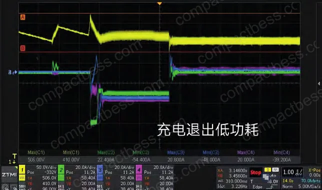
The root cause, confirmed by loss breakdown testing on the DC-DC stage, is switching loss in the main power topology. The solution isn’t a better capacitor or a control loop tweak — it’s stopping the switching entirely on packs that aren’t needed.
Honestly, most buyers over-specify continuous standby capability without ever asking what it costs in idle consumption. A pack that can hold 400 V bus indefinitely while doing nothing is impressive until you realize it’s drawing 70 W to do it. If your deployment has extended periods of low grid demand (overnight, low-season solar sites), this number will show up in your customer’s electricity bill.
Low-Power Mode: Intermittent Rotation Design #
The control strategy is a master-coordinated intermittent rotation scheme. One pack maintains system operation; the others enter a standby state with only auxiliary power running. The standby loss for an idle pack drops to approximately 4.6 W, versus 70 W active. Two packs in standby saves 128.8 W at the system level.
The active pack can additionally operate in an intermittent switching mode — periodically stopping its PWM switching to further cut its own losses. Combined, the system targets a total loss reduction of around 66% under light-load conditions versus baseline.
Entry Conditions #
Two conditions must be simultaneously satisfied to enter low-power mode:
- Average cell current across all packs is positive and below 3 A. At 50 V nominal cell voltage, three packs at 3 A each equals 450 W — this is the light-load threshold.
- Condition 1 must hold continuously for 10 seconds before mode transition is triggered.
The 10-second hold timer prevents nuisance trips from brief load transients.
Bus Voltage Operating Window #
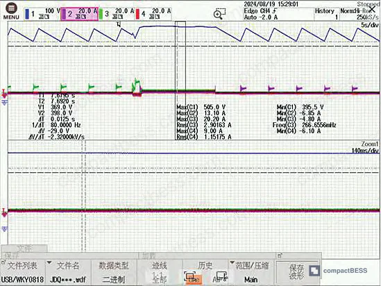
Measured data confirms that maintaining bus voltage in the 380 V to 480 V range minimizes losses during intermittent operation. This range defines the operating envelope for the active pack during rotation.
Pack Selection Logic #
The master pack is defined as the pack with the lowest address — this ensures deterministic selection with no arbitration ambiguity. The master pack monitors SOC data broadcast from all packs via CAN and selects the pack with the highest SOC as the intermittent (active) pack. This prioritizes energy-rich packs for duty and protects lower-SOC packs from additional drain.
Each pack maintains a local system information table — updated via timed broadcast — containing: pack address, cell voltage, cell current, SOC, and current intermittent pack address.
Exit Conditions #
Low-power mode exits under three conditions:
| Exit Trigger | Detection Method | Threshold | Notes |
|---|---|---|---|
| Rotation timeout | Intermittent pack internal timer | 10 minutes | Pack self-times, broadcasts exit to others |
| Charging detected | Current direction check + bus voltage rise | Charge current > 5 A (250 W at 50 V) | Any pack can detect; broadcast triggers full wakeup |
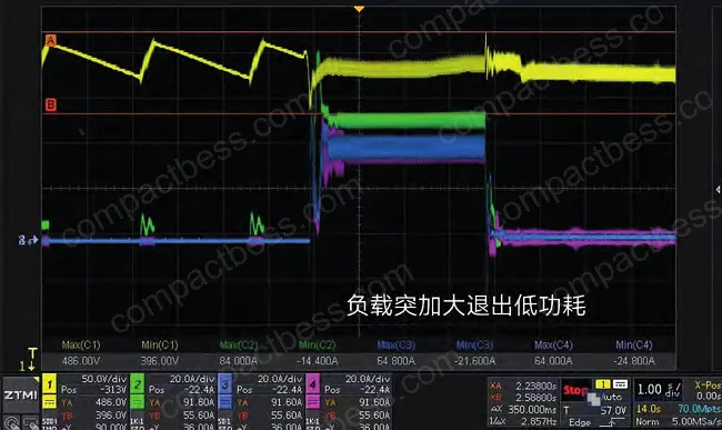
| Load increase | Bus voltage drop or current threshold | Load > 3 A (1.5 kW at 50 V) / bus < 420 V | Drop below 420 V triggers undervoltage prevention exit |
The charging exit uses a 510 V upper bus voltage threshold — positioned below the actual overvoltage protection trip point to give recovery headroom. The load-increase exit uses 420 V as the lower bound, above the undervoltage protection threshold, so the bus stabilizes before any protection trips.
In supplier qualification, we saw three of six samples from an early firmware revision fail the load-step exit condition: when a sudden full-load step was applied, bus voltage dropped through 420 V before the standby packs had fully re-enabled their switching stages. The result was a momentary undervoltage disconnect — exactly what the scheme is supposed to prevent. The fix required tightening the exit broadcast latency and pre-charging the DC-DC output capacitors before the pack declared itself “ready.” This is not a theoretical edge case. It will happen in field installations where loads are switched hard.
CAN Communication Protocol Requirements #
This entire scheme lives or dies on the CAN broadcast architecture. The communication layer has to handle three distinct tasks reliably:
Task 1 — Status broadcast: Each pack periodically broadcasts its own data (address, cell voltage, cell current, SOC, intermittent pack address) to all other packs on the bus. Every pack stores a complete, real-time system table locally. No pack depends on polling from a central controller.
Task 2 — Mode command broadcast: The master pack broadcasts low-power mode entry and exit commands. All packs act on these immediately.
Task 3 — Intermittent pack clear command: Any pack can notify the master to clear the current intermittent pack designation, triggering a new selection cycle.
The CAN frame format aligns with IEC 62576 and relevant EV charging communication standards — specifically consistent with the frame structures used in charging station communication protocols. This matters for interoperability: if you’re integrating these packs with a third-party PCS, the CAN framing must be compatible with the PCS’s expected message structure.
For buyers sourcing packs that claim CAN-based multi-pack coordination: ask explicitly whether the broadcast interval is fixed or adaptive. Fixed intervals work fine at 3 packs; at 6 or 8 packs in a larger system, bus utilization and latency stack up quickly. The broadcast design described here functions correctly at 3-pack scale — scalability to larger arrays needs independent validation.
Most procurement teams don’t realize that GB/T 34131 — the Chinese national standard governing BMS communication for energy storage — was substantially revised to align more closely with IEC 62619:2022 safety and functional requirements. Suppliers citing “GB/T compliance” without specifying the revision year may be referencing an outdated requirement set that doesn’t cover multi-pack CAN arbitration behavior under fault conditions.
For a deeper treatment of BMS communication protocol selection and interoperability requirements, see our BMS Communication Protocols guide for a full breakdown of CAN, RS485, and SMBus tradeoffs in multi-pack BESS deployments.
Test Results and Validation #
The test configuration: 3-pack system, 15 kWh total, 400 V nominal bus, light-load condition defined as system load below 450 W.
Baseline loss (no low-power mode, 3 packs active): ~210 W
Standby loss per idle pack: ~4.6 W
Two idle packs combined: ~9.2 W
System loss reduction achieved: ~66%
The 66% reduction was confirmed across extended run cycles. Figure 2 (waveform data) shows the bus voltage transient when a full load step is applied during low-power mode: bus voltage (CH1) experiences a drop over a 10 ms window before recovering to stable state. This is the critical handoff window — 10 ms is acceptable for most residential PCS designs, but verify against your PCS undervoltage ride-through specification before deploying.
Long-term rotation testing confirmed that the SOC-priority selection logic distributes wear across packs effectively, preventing any single pack from accumulating disproportionate discharge cycles during standby rotation.
For buyers evaluating this type of system against IEC 62619:2022 (Safety requirements for secondary lithium cells and batteries for use in industrial applications) and UL 9540 for energy storage system certification: the low-power mode logic needs to be explicitly validated as part of the protection scheme review. Specifically, confirm that the exit threshold voltages (510 V upper, 420 V lower) remain compliant with your system’s protection trip points, and that the broadcast latency under worst-case CAN bus load doesn’t exceed what your protection timing budget allows.
For SOC estimation accuracy requirements that feed this selection logic, refer to our SOC Estimation Methods documentation — accurate SOC is directly upstream of correct pack rotation decisions.
Comparison: Operating Modes at a Glance #
| Parameter | Normal Operation (3 packs active) | Low-Power Mode (1 intermittent + 2 standby) | Standby Only (all packs idle aux) |
|---|---|---|---|
| System standby loss | ~210 W | ~70–80 W (estimated with intermittent switching) | ~13.8 W (3 × 4.6 W) |
| Bus voltage range | 380–480 V (nominal) | 380–480 V (maintained by active pack) | Not maintained |
| Load response capability | Full 12 kW (3 × 4 kW) | Up to 4 kW (single pack), others recover in <10 ms | Requires full wakeup |
| CAN broadcast requirement | Standard status | Status + mode commands + rotation commands | Minimal |
| Applicable load range | >450 W system load | <450 W system load | Grid-disconnected / zero load |
Practical Guidance for Buyers #
When you’re qualifying a multi-pack BESS supplier on light-load efficiency, don’t accept a single efficiency figure at rated power. Ask for measured standby loss at the system level — not per-cell, not per-pack in isolation, but for the full parallel configuration under no-load and light-load conditions. That number should be in their datasheet. If it isn’t, assume it’s bad.
The scheme described here achieves 66% standby loss reduction through firmware control alone — no hardware changes, no additional components. That’s significant, and it means firmware version matters. Ask your supplier which firmware revision implements low-power mode, what the validated rotation interval is, and whether the CAN exit broadcast has been tested under maximum bus load conditions.
Verify that exit voltage thresholds (typically 420 V lower, 510 V upper for a 400 V bus system) are documented and have been type-tested, not just simulated. The 10 ms load-step transient window is your key integration parameter — confirm it against your PCS undervoltage specification before signing off on system-level acceptance.
For systems deploying 5+ packs, the broadcast-based coordination logic described here should be re-validated. Three-pack behavior is well-characterized; larger arrays introduce CAN utilization and arbitration timing concerns that require independent testing under your specific configuration.
Frequently Asked Questions #
Q1: What is the measured standby loss reduction achievable with coordinated low-power mode in a 3-pack 15 kWh system?
Tested reduction is approximately 66% — from a baseline of ~210 W (3 packs active, no low-power mode) down to roughly 70–80 W in practice. The two idle packs in standby-only state account for approximately 9.2 W combined (4.6 W each), with the bulk of the remaining loss in the single active intermittent pack’s switching stage.
Q2: Why does the pack with the highest SOC get selected for intermittent duty rather than the lowest?
It’s counterintuitive but correct. The intermittent pack will consume its own stored energy while maintaining the bus. Selecting the highest-SOC pack preserves the lower-SOC packs and keeps the system energy distribution more balanced over time. After the 10-minute rotation interval, a new selection runs and the next highest-SOC pack takes over duty.
Q3: Can this low-power mode architecture scale to 6 or 8 packs?
The paper validates the scheme at 3-pack scale. The broadcast-based CAN coordination works by having every pack maintain a full local system table — this is efficient at 3 packs but CAN bus utilization and broadcast latency grow with pack count. For larger arrays, request independent validation data from your supplier. Don’t assume 3-pack test results transfer directly.
Q4: What CAN communication standards should I reference when specifying multi-pack BMS protocol compliance?
Reference IEC 62619:2022 for safety and functional requirements and GB/T 34131 for BMS communication — but verify the revision year on the latter. Also confirm the CAN frame format is consistent with your PCS manufacturer’s expected protocol, particularly for mode-command and broadcast frame types.
Q5: What is the bus voltage exit threshold for the undervoltage protection handoff, and why does it matter?
The lower exit threshold is set at 420 V, above the actual undervoltage protection trip point. This margin ensures the bus stabilizes before any protection relay can trigger. Getting this wrong — as we observed in early-revision firmware testing — results in a nuisance disconnect during load steps. It’s a critical parameter to verify during factory acceptance testing, not something to discover in the field.
Published by compactbess.com Technical Team | Request a sourcing quote
Content reviewed by elena.fischer | © compactbess.com — All rights reserved. Unauthorized reproduction prohibited.


