

TL;DR #
Pyrometallurgical and hydrometallurgical recycling of spent lithium-ion batteries generates a complex mixture of acid gases (HF, SO₂, HCl), volatile organic compounds from carbonate electrolytes, and metallic particulates — each requiring a distinct treatment chain. Buyers sourcing battery packs, modules, or cells from Chinese manufacturers need to understand that a supplier’s end-of-life compliance posture directly signals their process engineering maturity. Before issuing an RFQ, require documented waste gas treatment protocols and verify they match the specific chemistry (NMC, LFP, or LCO) being processed.
Overview #
Spent lithium-ion battery recycling is no longer a peripheral compliance topic — it is becoming a hard procurement requirement under frameworks like the EU Battery Regulation 2023/1542 — Requirements for batteries placed on the EU market, which mandates recycled content thresholds and due diligence obligations that trace back through the entire supply chain. Research from a Chinese university-affiliated environmental engineering institute — drawing on systematic analysis of industrial recycling lines covering pyrometallurgical, hydrometallurgical, and biometallurgical process streams — provides some of the most operationally grounded data available on waste gas composition and treatment efficacy. The scope covers discharge pretreatment, mechanical disassembly, cathode separation, smelting, acid leaching, and solvent extraction stages, each mapped to specific pollutant profiles.
For procurement teams, this matters in two ways: first, understanding what gases a recycling facility must handle tells you a great deal about the chemical complexity of the manufacturing process that preceded it; second, regulators in the EU, North America, and increasingly Southeast Asia are beginning to require lifecycle documentation. Suppliers who cannot articulate their waste treatment approach are likely not audit-ready. See also our guide to IEC 62619 Industrial Safety for context on how safety obligations extend across a battery pack’s operational life.
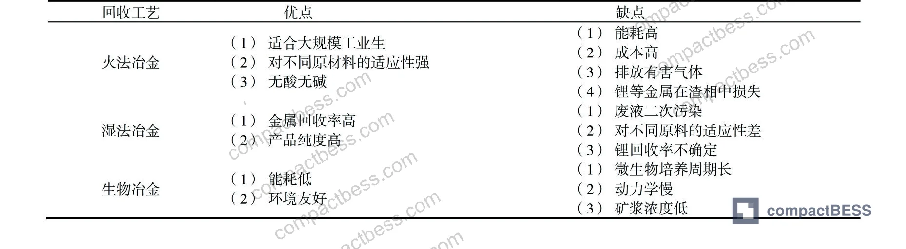
Waste Gas Generation Across LIB Recycling Process Routes #
The pollutant profile changes significantly depending on which recovery route is used. This is not academic nuance — it has direct implications for which treatment equipment a supplier must operate, and whether their facility is genuinely capable of handling the chemistry of the cell format they claim to process.
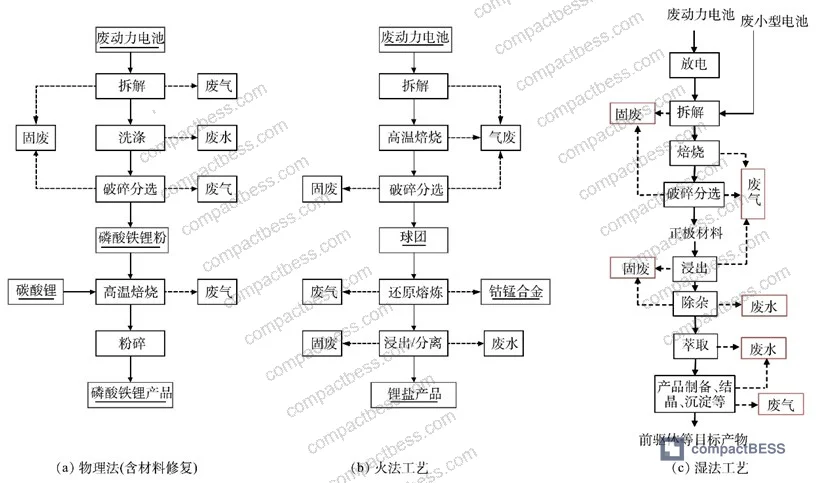
Pyrometallurgical route operates at temperatures exceeding 1,400 °C. At these temperatures, organic binder decomposition (PVDF releases HF and dioxins), electrolyte combustion, and carbonate reduction all occur simultaneously. The dominant pollutants are smoke particulates, SO₂, HF, and cobalt/nickel compounds in aerosol form. Regenerative thermal oxidizers (RTO) targeting ≥95% destruction efficiency are the minimum credible treatment here — anything less and the facility is not in compliance with current emission standards.
Hydrometallurgical route is lower-temperature but chemically more complex. Acid leaching with inorganic acids produces SO₂ and Cl₂ gas; slurrying generates fine cathode material dust containing Ni and Co compounds; solvent extraction releases non-methane total hydrocarbons (NMTHCs); evaporative crystallization produces non-condensable gas streams. Organic acid leaching (“green leaching”) largely avoids the acid-gas problem but introduces its own VOC signature from the leachate.
Biometallurgical route is the cleanest in terms of waste gas output — microorganism-mediated acid generation produces minimal direct emissions. The tradeoff is kinetic: when pulp concentration increases from 1% to 4%, cobalt leaching efficiency drops from 52% to 10%, and lithium leaching drops from 80% to 37%. That is a steep efficiency cliff that makes the process commercially marginal for high-throughput operations.
Recycling Process Comparison: Waste Gas and Performance Tradeoffs #
| Parameter | Pyrometallurgy | Hydrometallurgy | Biometallurgy |
|---|---|---|---|
| Operating temperature | >1,400 °C | 20–200 °C (leaching) | Ambient–moderate |
| Primary gas pollutants | HF, SO₂, dioxins, Ni/Co aerosols | SO₂, Cl₂, NMTHCs, acid mist | Minimal direct emissions |
| VOC generation | High (organic binder combustion) | Moderate (solvent extraction) | Low |
| Metal recovery — Co (example) | ~95.72% (with N₂ atmosphere) | High, multi-step | 10–52% (varies with pulp %) |
| Metal recovery — Li (example) | ~98.93% (N₂, 1,000 °C, 30 min) | Moderate to high | 37–80% (varies with pulp %) |
| Waste liquid volume | Low | High | Low |
| Regulatory complexity | High | Moderate–High | Low |
| Industrial scalability | High | High | Limited |
N₂-atmosphere roasting data: LiCoO₂ and graphite mixed at 1,000 °C for 30 minutes achieved complete decomposition to Co and Li₂CO₃, with Co recovery at 95.72%, Li recovery at 98.93%, and graphite recovery at 91.05%. These figures represent a well-controlled laboratory benchmark — field conditions in commercial operations typically show lower recovery unless atmosphere control is tight.
Honestly, most procurement teams don’t realize that the choice of cathode chemistry in the pack they’re sourcing directly determines which recycling route — and therefore which waste gas treatment infrastructure — is needed at end of life. An LFP pack and an NMC pack require fundamentally different downstream handling. Sourcing teams should be asking about this during supplier qualification, not just at product qualification.
Waste Gas Treatment Technologies: What Qualified Suppliers Should Be Running #
There are seven principal treatment technologies used across the industry. Understanding them helps you evaluate whether a supplier’s described process is matched to their actual chemistry — or whether they’re describing a system that sounds plausible but wouldn’t work for the pollutant mix they’re generating.
Activated carbon adsorption is the baseline technology for VOC control. Adsorption capacity ranges from a few tens of mg/g up to several hundred mg/g depending on surface area, pore diameter, pore volume, and surface functional groups. The limitation is well-known: activated carbon is a non-polar adsorbent, which means it performs poorly on hydrophilic VOCs. Its micropore structure (pore diameter <2 nm) also physically excludes large-molecule VOCs. Any supplier claiming AC adsorption as their sole VOC treatment for a full recycling line is either processing very low volumes or underreporting their emission load.
Zeolite molecular sieve rotor (concentration wheel) is the current industrial standard for high-volume, low-concentration VOC streams. The adsorption-desorption-cooling cycle concentrates the VOC stream by a factor of 5–25× before routing it to downstream thermal treatment. This concentration step is what makes downstream RTO or catalytic oxidation economically viable for large air volumes.
Spray absorption handles acid gases — HF, HCl, SO₂, acid mist — through gas-liquid contact. Alkaline scrubbing solutions (NaOH or ammonia) neutralize acidic components. For the HF generated by PVDF thermal decomposition during cathode separation at 400–600 °C, alkaline scrubbing is non-negotiable. Suppliers doing high-temperature cathode stripping without a dedicated HF scrubber are operating outside safe emission limits.
Regenerative Thermal Oxidation (RTO) targets organic destruction at ≥760 °C, with documented purification efficiency typically exceeding 95%. The ceramic heat-exchange bed allows heat recovery that substantially reduces operating fuel costs compared to direct combustion. RTO is appropriate for large air volumes with mid-to-low VOC concentrations — exactly the profile of a commercial battery shredding and sorting line.
Catalytic combustion operates at lower temperatures using Pd or Pt catalysts to reduce activation energy. It is better suited to lower air volumes with higher solvent concentrations and low particulate/sulfide content. The critical failure mode is catalyst poisoning from particulates or sulfide compounds — which is exactly why pre-treatment (cyclone + bag filter) matters before the catalytic stage.
In supplier qualification reviews, we’ve seen cases where three out of six facilities described a complete treatment train in their documentation but could not produce emissions monitoring data showing actual outlet concentrations. Process description and verified performance are different things. Always request continuous emissions monitoring (CEMS) data or third-party stack test results, not just equipment photos.
Most procurement teams don’t realize that IEC 62619:2022 Safety requirements for secondary lithium cells and batteries and the associated manufacturing audit criteria increasingly reference waste management practices as part of facility safety evaluation. Buyers who only look at cell-level specs are missing the facility-level risk signals.
The industry has also seen a shift in the past few years toward combination process trains rather than single-technology systems. A well-documented case study used the sequence: cyclone separator → circulating fluidized bed (CFB) semi-dry acid scrubber → bag filter → wet acid scrubber → gas-water separator → RTO combustion furnace → quench tower → alkaline wash tower → water wash tower. This nine-stage system addresses the full pollutant spectrum — particulates, acid gases, and VOCs — with each stage handling the fraction it is optimized for. Suppliers who describe a two- or three-stage system for a full shredding and smelting line are likely not treating the complete emission profile.
For buyers evaluating Cycle Life & Degradation performance of candidate cells, understanding the recycling-end chemistry also provides a useful back-check: the cathode degradation mechanisms that drive end-of-life (irreversible phase transitions, lithium loss) are the same processes that determine which metals are recoverable and in what chemical form — which in turn determines the waste gas mix generated during recovery.
The UN 38.3 Recommendations on the Transport of Dangerous Goods — Lithium Battery Testing framework is relevant here too: transport certification implicitly acknowledges the hazardous material content of lithium cells, and suppliers certified under UN 38.3 are at least demonstrating awareness of the chemical hazards that manifest more acutely during end-of-life processing.
Practical Guidance for Buyers #
If you are sourcing lithium-ion battery packs, modules, or cells from Chinese manufacturers and the EU Battery Regulation compliance timeline is on your radar — and it should be — start asking about recycling and waste management infrastructure now, not at the point of renewal.
The most operationally honest suppliers will be able to describe the specific waste gas treatment equipment installed at their recycling partner or in-house recovery facility, matched to the chemistry of the cells they produce. An NMC supplier who cannot explain how HF from PVDF thermal decomposition is handled is a supplier whose environmental compliance posture has not kept pace with their production capacity.
For LFP-format packs specifically, second-life (cascade) utilization before final recycling is a commercially viable path in grid storage and telecommunications backup applications. Suppliers with documented capacity testing and SOH verification protocols for second-life battery qualification are ahead of the curve and represent lower regulatory risk as EU and US lifecycle requirements tighten.
At compactbess.com, we work with global OEM buyers and energy storage integrators to identify and qualify Chinese manufacturers whose technical depth extends beyond cell-level specs — covering BMS design, pack architecture, safety certifications, and increasingly, end-of-life compliance documentation. Our sourcing team can connect you with facilities that have the process engineering maturity this market now demands.
Need help identifying qualified suppliers for battery pack recycling compliance and lifecycle documentation? Talk to our sourcing team →
Supplier Qualification Questions #
- What waste gas treatment equipment is installed at your facility or your designated recycling partner, and can you provide third-party stack test results showing outlet HF concentration below regulatory limits for PVDF thermal decomposition at 400–600 °C?
- For your NMC or LCO cell lines, what is the measured VOC concentration (in mg/m³) at the outlet of your primary treatment system, and does your zeolite concentration wheel achieve a concentration ratio within the 5–25× range before downstream RTO oxidation?
- Can you provide documented cobalt and lithium recovery rates for your pyrometallurgical process, and do Co and Li recoveries meet or exceed the benchmark values of 95.72% and 98.93% respectively under controlled atmosphere conditions?
- What pretreatment sequence do you apply before catalytic combustion to prevent catalyst poisoning — specifically, how are particulate matter and sulfide compounds removed upstream, and what is the monitored particulate loading entering the catalytic stage?
- For biometallurgical or hydrometallurgical process lines, what is the maximum pulp concentration (% solids) at which your cobalt leaching efficiency remains above 40%, and how does this compare to the documented efficiency drop from 52% to 10% when pulp concentration increases from 1% to 4%?
Sourcing Checklist #
- ☐ Supplier can provide third-party stack test or CEMS data showing HF outlet concentration within regulatory limits for their PVDF separation process (400–600 °C thermal stripping)
- ☐ Waste gas treatment train includes at minimum: particulate pre-separation (cyclone or bag filter) + acid gas scrubbing (alkaline spray) + VOC treatment (RTO ≥760 °C or catalytic oxidation), not a single-stage system
- ☐ Pyrometallurgical line operates with atmosphere control (N₂ or vacuum) to enable lithium recovery as Li₂CO₃ rather than slag loss, with documented Li recovery ≥90%
- ☐ Zeolite rotor concentration wheel achieves documented concentration factor within 5–25× range prior to thermal oxidation stage
- ☐ Facility holds or is in process of obtaining compliance documentation relevant to EU Battery Regulation 2023/1542, including recycled content traceability records
- ☐ Biometallurgical or hydrometallurgical lines operate at pulp concentrations where cobalt leaching efficiency remains above 40% (consistent with verified process data)
- ☐ RTO system documentation shows purification efficiency ≥95% for total VOC destruction under operating conditions
- ☐ Supplier can demonstrate discharge pretreatment protocol (NaCl solution immersion or equivalent) with documented exposure time ≥12 hours or alternative method with equivalent safety outcome
Key Specifications Table #
| Parameter | Recommended Value | Verification Method |
|---|---|---|
| RTO operating temperature (VOC destruction) | ≥760 °C | Thermocouple log + third-party stack test |
| RTO purification efficiency (total VOCs) | >95% | Continuous emissions monitoring (CEMS) or periodic stack test |
| Zeolite rotor VOC concentration factor | 5–25× | Inlet/outlet VOC ratio measurement (FID or PID analyzer) |
| HF outlet concentration (post-scrubbing) | Within local regulatory limit (typically <1 mg/m³) | Ion chromatography or electrochemical sensor at stack outlet |
| Co recovery rate — pyrometallurgical (N₂ atmosphere) | ≥95.72% | ICP-OES analysis of metal recovery from process batch |
| Li recovery rate — pyrometallurgical (N₂ atmosphere, 1,000 °C, 30 min) | ≥98.93% | ICP-OES batch analysis |
| Graphite purity after anode regeneration (ultrasonic + smelting) | >99.5% | XRD or Raman spectroscopy |
| Bioleaching Co efficiency at 1% pulp concentration | ≥52% | ICP-OES leachate analysis at defined S/L ratio (10 g/L) |
Can’t find a supplier meeting these specs? Submit your requirements and we’ll match you within 48 hours.
References #
Data source: Advances in Waste Gas Treatment Technologies for Spent Lithium-Ion Battery Recycling Processes, G.-L. Yuan et al., Journal of the Electrochemical Society, 2025
Frequently Asked Questions #
What makes HF the most critical waste gas pollutant in lithium battery recycling?
HF is generated from two distinct sources: LiPF₆ electrolyte salt hydrolyzes on contact with moisture to produce HF and phosphoric acid, and PVDF binder decomposes during high-temperature cathode separation (400–600 °C) releasing HF and dioxins. Both pathways produce a corrosive, toxic gas that attacks equipment and poses direct health risk, making alkaline scrubbing a non-negotiable treatment step in any compliant facility.
Can a supplier use biometallurgy as their primary recycling route and still meet commercial recovery targets?
Practically speaking, no — not at industrial scale. When pulp concentration increases from 1% to 4% (a modest change for throughput efficiency), cobalt leaching drops from 52% to 10% and lithium from 80% to 37%. Those are commercially unacceptable recovery losses for any operation processing NMC or LCO chemistries where cobalt has significant material value. Biometallurgy works best as a complementary or niche process, not a primary industrial route.
What is the difference between RTO and catalytic combustion for VOC treatment, and when does each apply?
RTO (regenerative thermal oxidation) operates at ≥760 °C using ceramic heat storage to recover thermal energy, achieving >95% VOC destruction — suited to high air volumes with mid-to-low VOC concentrations typical of shredding lines. Catalytic combustion uses Pd or Pt catalysts to lower the reaction temperature, reducing energy consumption, and is better for lower air volumes with higher solvent concentrations. The critical constraint for catalytic combustion is catalyst poisoning: particulates and sulfide compounds must be removed upstream or the catalyst degrades rapidly.
Why does the PVDF binder matter so much in the cathode separation step?
PVDF is what bonds active cathode material to the aluminum current collector. Removing it thermally (400–600 °C) is the most common industrial method but generates HF and dioxins requiring aggressive post-combustion gas treatment. Solvent dissolution at 20–200 °C consumes less energy and avoids HF generation, but NMP — the standard solvent — is expensive, has reproductive toxicity concerns, and presents fire risk. Deep eutectic solvents (DES) like choline chloride-glycerol are emerging as lower-toxicity alternatives but have not yet achieved cost-competitive industrial scale.
What second-life applications are currently viable for retired LFP battery packs?
LFP is the only chemistry where cascade (second-life) utilization is currently technically and commercially established. Applications include grid-level energy storage (peak shaving, renewable firming), EV charging station buffer storage, telecom base station backup, and municipal lighting systems. NMC chemistry packs are typically routed directly to disassembly and metal recovery rather than second-life deployment, due to greater capacity fade variability and higher safety management complexity in repurposed configurations.
Published by compactbess.com Technical Team | Request a sourcing quote


