

TL;DR #
A three-tier BMS architecture using CAN bus for cell-level data and RS-485/Modbus for upstream integration reduces UPS fault response time to under 3 seconds across all alarm categories, with field deployment at a large coal chemical plant confirming repeated successful fault push notifications that prevented battery-caused UPS outages. For buyers sourcing BMS-integrated UPS systems for industrial or chemical-sector applications, this means the communication architecture and alarm latency spec matter as much as the battery chemistry choice. Before issuing any RFQ, confirm that the BMS supports both CAN bus (cell-to-master) and RS-485/Modbus (master-to-SCADA) simultaneously, with configurable three-tier alarm thresholds and ≤3 s detection delay.
Overview #
Most procurement teams approach UPS battery monitoring as an afterthought — something bolted on after the main UPS spec is locked. That’s a costly mistake in industrial environments. The moment a UPS failure cascades into a DCS or SIS outage at a chemical plant, you’re not talking about equipment replacement costs; you’re talking about production shutdowns and potential safety incidents.
The engineering data referenced here comes from a large-scale field implementation at a coal chemical industrial group, covering both a greenfield lithium battery UPS deployment and a retrofit of legacy lead-acid UPS systems — all integrated under a unified BMS and industrial IoT platform. The scope included multiple cabinet rooms across multiple plant zones, which makes this one of the more realistic multi-UPS BMS validation cases available in recent published literature. Each lithium cell in the system operated at 3.2 V per cell, with 8 cells per module box and 24 cells per slave control unit — giving procurement engineers concrete reference points for matching BMS hardware to pack configuration.
The core finding: alarm detection delay was standardized at 3 seconds across all three alarm tiers for voltage, temperature, current, insulation, and communication faults. That number should be in your technical specification.
BMS Architecture for UPS Systems: Three-Tier Design and Communication Protocols #
The BMS architecture that performed reliably in field deployment follows a strict three-tier hierarchy. Understanding this structure is essential when evaluating supplier offerings, because a flat or two-tier BMS will struggle to scale across a multi-zone industrial facility.
Tier 1 — Slave Control Units (Data Acquisition Layer)
Each slave unit manages 24 cell strings, acquiring voltage per cell, plus 8 temperature measurement points per unit. Passive cell balancing is implemented at this tier. Communication to the master uses CAN bus — the right choice for noise immunity in industrial cabinet environments.
Tier 2 — Master Control Unit
The master aggregates total pack voltage, total current via shunt, pre-charge circuit status, and main contactor state. It communicates downward to slaves via CAN bus and upward to the central controller via RS-485.
Tier 3 — Central Control Unit (BCU)
The Battery Cluster Unit consolidates all master data, drives the touchscreen HMI, sets alarm parameters, and acts as the gateway for RS-485 communication to both the DCS and the SCADA/IoT platform. It controls charge relays, discharge relays, and pre-charge relays directly.
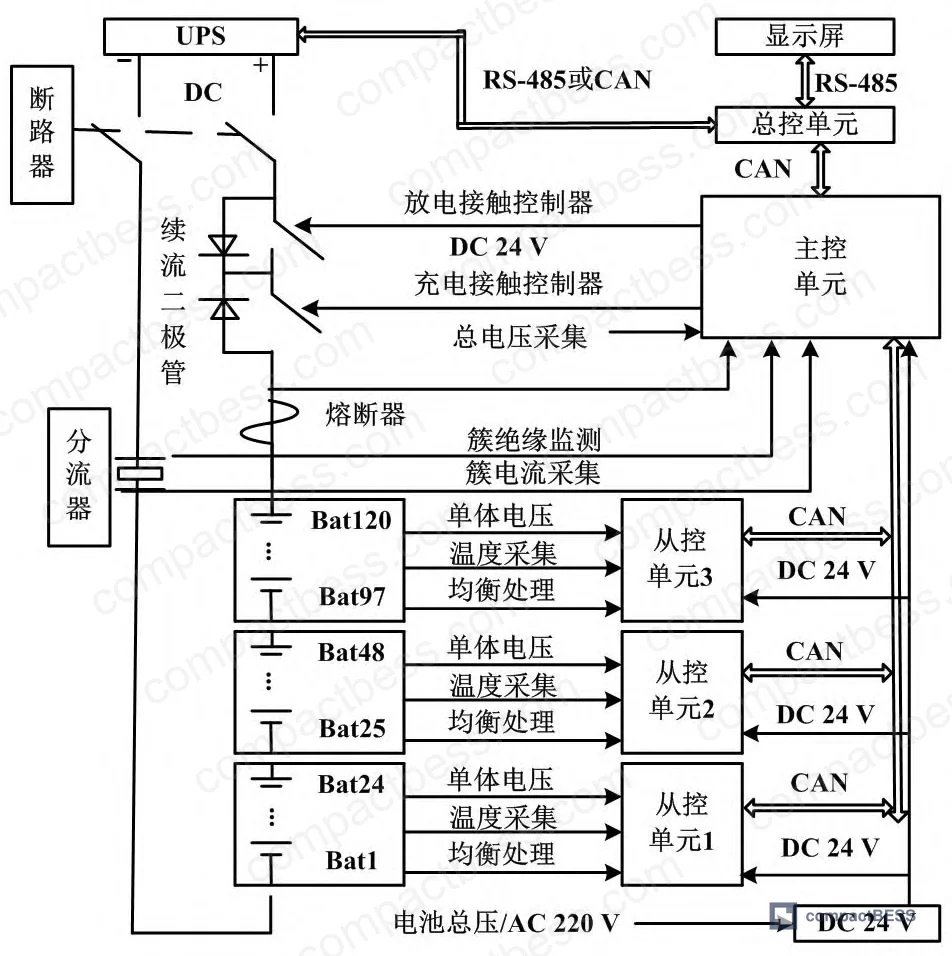
This tiered architecture directly determines sensor count and wiring complexity. For the lithium system, each module box contains 8 cells, each with a dedicated temperature, current, and voltage sensor set — 8 sensor groups per module box. The lead-acid retrofit, by contrast, requires only 2–3 slave units per UPS system because individual lead-acid cells run at 24 V each, and the cell count per string is much lower.
| Parameter | Lithium Battery System | Lead-Acid Battery System |
|---|---|---|
| Cell voltage | 3.2 V per cell | 24 V per cell |
| Cells per slave unit | 24 series strings | 2–3 slave units per UPS |
| Sensor groups per module | 8 sets (per module box) | Fewer sensors per string |
| Cell balancing method | Passive balancing at slave tier | Not specified |
| Communication: slave → master | CAN bus | CAN bus |
| Communication: master → DCS | RS-485 / Modbus | RS-485 / Modbus |
| HMI interface | Touchscreen via RS-485 | Touchscreen via RS-485 |
| Small UPS requirement | Multiple slave units | 1 slave unit sufficient |
Honestly, most buyers over-specify the BMS communication layer when they’re replacing lead-acid with lithium. A lead-acid retrofit doesn’t need the same slave unit density — 2 to 3 slave units and a single master will cover most industrial UPS sizes. Where buyers under-specify is the alarm configuration depth: they accept a single-threshold alarm when a three-tier configurable alarm structure is what’s needed to catch early degradation before it becomes a shutdown event.
The alarm parameter table from the field deployment is worth reproducing directly. Every one of the following alarm categories was configured with a 3-second detection delay and three configurable severity tiers:
- Total pack voltage (high/low)
- Discharge terminal voltage
- Individual cell voltage (over-voltage and under-voltage)
- Charge/discharge temperature high
- Charge/discharge temperature low
- Charge/discharge overcurrent
- Insulation leakage fault
- Chip fault (1-second detection delay)
- Communication fault (1-second detection delay)
That 3-second delay is a deliberate design choice — fast enough to catch acute faults, slow enough to avoid nuisance trips from transient noise. For chip and communication faults, the delay drops to 1 second. All three-tier alarms require manual intervention to clear. This is non-negotiable in a chemical plant context where a spurious alarm clear could mask a real degradation event.
Compliance with IEC 62619 for industrial lithium battery safety and GB/T 50770-2013 (Petrochemical Safety Instrumentation Design Specification) for dual-UPS power supply requirements in DCS/SIS systems should be baseline requirements in any RFQ targeting chemical industry UPS applications. The dual-bus redundant UPS topology specified under that standard has been shown to substantially reduce overall UPS fault rates in field deployments.
Industrial UPS Monitoring System Integration: SCADA, DCS, and Cybersecurity Architecture #
Getting the BMS hardware right is only half the problem. The other half is data integration — and this is where most procurement teams don’t realize that industrial cybersecurity requirements have tightened considerably in recent years. Current industry practice in process automation increasingly mandates hardware firewalls and unidirectional data gateways between BMS/DCS systems and any cloud or mobile-accessible platform. Ignoring this in your system specification is a compliance risk that can delay commissioning.
The architecture validated in this field deployment addresses the integration challenge in three layers:
DCS Integration: BMS data is transmitted via RS-485/Modbus to the DCS, with key parameters filtered before upload to preserve DCS data quality. A dedicated UPS monitoring screen is configured in the DCS for process operators, with alarm pop-up functionality. Data encoding follows a standardized 13-character structure: 5-digit company code + 2-digit zone code + 3-digit cabinet room code + 3-digit equipment code. This encoding is what prevents data management chaos when you’re managing dozens of UPS systems across multiple plant zones.
Network Security Layer: A hardware firewall sits between the DCS and the data acquisition system, operating on a whitelist mechanism for one-way data transfer. The data acquisition system uses a private cloud with high-availability architecture. Data passes through an isolation gateway into the SCADA/IoT platform. The full industrial cybersecurity stack — including situational awareness platform, logging, and audit systems — was commissioned as part of this deployment. This is consistent with current requirements under IEC 62443 for industrial automation cybersecurity.
Mobile/SCADA Notification: The supOS industrial IoT platform receives cleaned and structured data, performs analytics, and pushes alarm notifications to enterprise mobile applications (WeChat Work in this case, though the architecture is platform-agnostic). The interface supports browser/server (B/S) and client/server (C/S) access modes, meaning operators can monitor UPS status from PC, tablet, or phone.
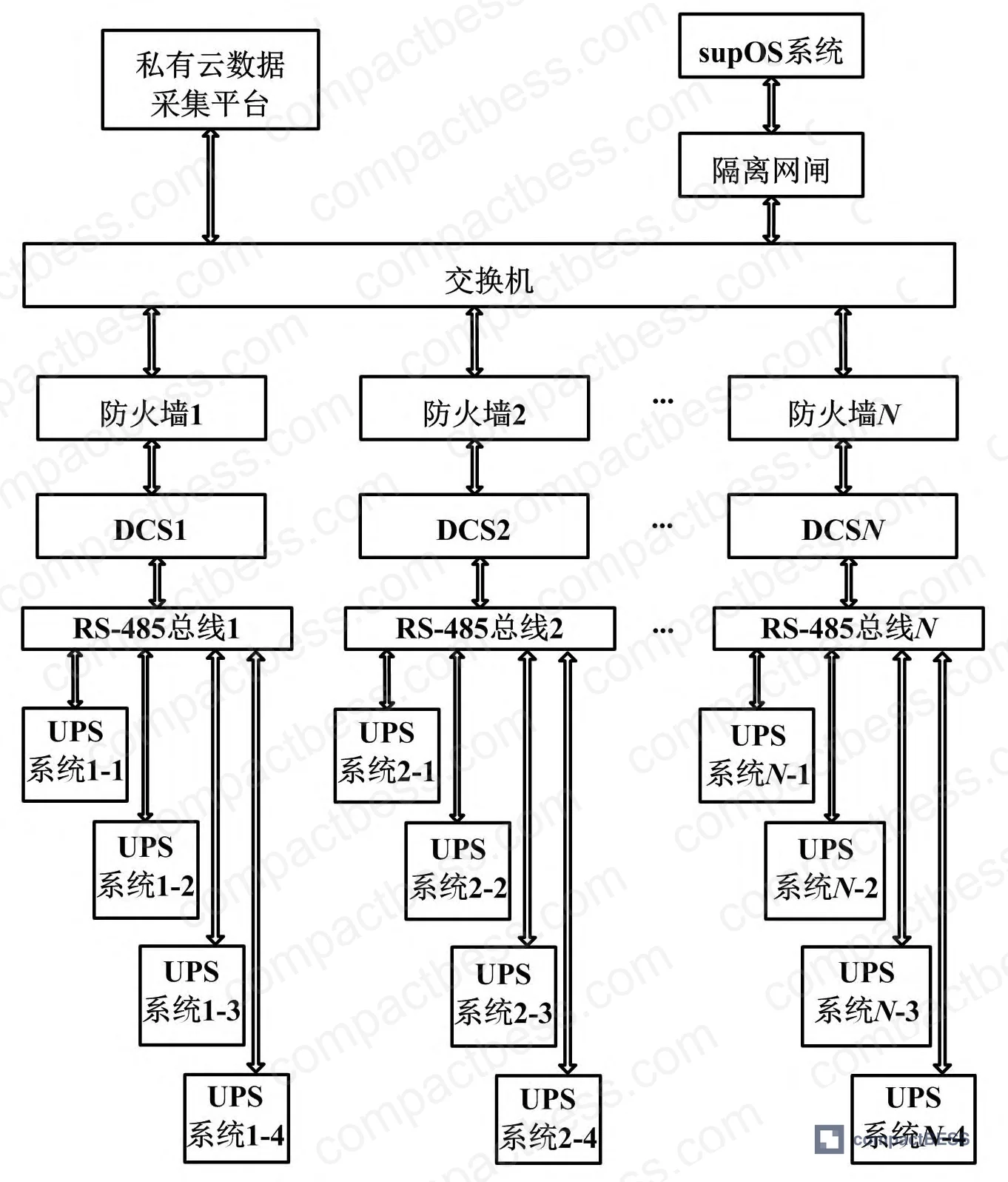
In supplier qualification, we’ve seen projects where three of six BMS vendors submitted for evaluation had no provision for hardware firewall integration — their systems assumed a direct network connection between BMS and cloud platform. In a chemical plant context, that’s an automatic disqualification. The risk of an external virus compromising a DCS through an inadequately isolated BMS network is not theoretical; it has caused production system paralysis and significant losses in documented incidents at process industry facilities.
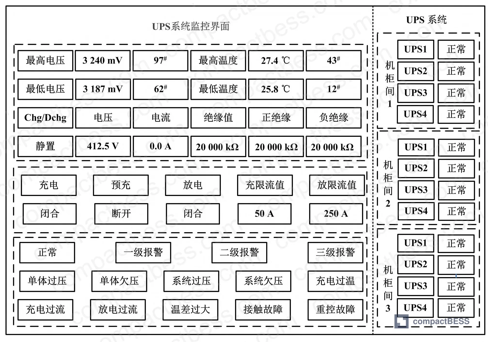
The supOS monitoring interface organizes UPS systems by cabinet room, displaying normal/fault status at a glance. Clicking any UPS unit populates the left panel with real-time host and battery parameters plus active alarms. After the BMS and mobile application went live in the field deployment, fault push notifications were triggered multiple times — and in each case, the alerts allowed maintenance personnel to intervene before a battery fault cascaded into a UPS outage. That’s the outcome metric that matters: not mean time between failures in a lab, but successful fault interception in a live plant.
For buyers evaluating portable UPS systems or industrial BMS modules, the communication architecture standards referenced here apply equally to smaller-scale deployments. The BMS communication protocol selection — specifically the CAN bus vs. RS-485 tier split — is the first thing to validate against your system integration requirements.
Practical Guidance for Buyers #
If you’re sourcing BMS-integrated UPS systems for an industrial facility — particularly any process industry or chemical sector application — the single biggest procurement error I see is treating BMS as a checkbox rather than a system integration specification. Get the alarm architecture, communication protocols, and cybersecurity isolation requirements into the RFQ document before you talk to suppliers. Suppliers who can’t answer questions about their three-tier alarm configuration or their hardware firewall interface are not qualified for this application.
For lead-acid retrofit projects, verify that the supplier’s BMS can handle per-cell sensor retrofits (voltage, current, temperature on every cell) with only 2–3 slave units per system. For new lithium deployments, confirm that the slave unit supports 24-cell string acquisition with 8 temperature points and passive balancing. Either way, the 3.2 V per cell nominal, 3-second alarm detection delay, and three-tier alarm severity structure should be in your minimum technical requirements.
At compactbess.com, we work directly with verified Chinese manufacturers of BMS modules, UPS systems, and lithium cell packs — connecting global OEM buyers and energy storage integrators with suppliers who can meet industrial-grade specifications. If you’re in the early stages of a BMS-integrated UPS sourcing project, our team can help you filter qualified suppliers against your specific communication, cybersecurity, and alarm architecture requirements.
Need help identifying qualified suppliers for BMS-integrated industrial UPS systems? Talk to our sourcing team →
Supplier Qualification Questions #
- What is the per-cell voltage acquisition range of your slave control unit, and can it handle 24 series cell strings with individual cell voltage monitoring at 3.2 V nominal per cell?
- What is the alarm detection latency for cell voltage, temperature, and overcurrent faults — specifically, can you achieve ≤3 seconds for three-tier configurable alarms, and ≤1 second for chip and communication fault detection?
- Does your BMS support simultaneous CAN bus communication (slave-to-master tier) and RS-485/Modbus communication (master-to-DCS/SCADA tier) without requiring a protocol converter?
- How does your system handle hardware firewall or isolation gateway integration between the BMS network and an upstream DCS or cloud SCADA platform — and have you deployed this in a IEC 62443-compliant industrial cybersecurity architecture?
- For a lead-acid battery retrofit, how many slave control units are required per UPS system when individual cell voltage, current, and temperature sensors are installed on each cell at 24 V per cell, and can your system scale to manage multiple UPS units across multiple plant zones under a single unified data encoding scheme?
Sourcing Checklist #
- [ ] BMS slave unit supports ≥24 series cell string voltage acquisition with individual cell resolution at 3.2 V nominal per cell
- [ ] Alarm detection delay is ≤3 seconds for all three-tier voltage, temperature, current, and insulation fault categories (configurable via panel)
- [ ] Chip fault and communication fault detection delay is ≤1 second
- [ ] BMS architecture implements CAN bus (slave ↔ master) and RS-485/Modbus (master ↔ DCS) as separate communication tiers — no single-bus flat architecture
- [ ] System supports per-cell temperature sensor acquisition with ≥8 temperature measurement points per slave unit
- [ ] Hardware firewall or certified isolation gateway is provided as part of the BMS-to-SCADA data path, consistent with IEC 62443 industrial cybersecurity requirements
- [ ] BMS supports three-tier configurable alarm severity levels with manual-clear-only requirement for tier-3 alarms (no auto-reset)
- [ ] Supplier can demonstrate field deployment in a process industry (chemical, petrochemical, or equivalent) environment with documented fault notification delivery to mobile platform
Key Specifications Table #
| Parameter | Recommended Value | Verification Method |
|---|---|---|
| Cell nominal voltage (lithium) | 3.2 V per cell | BMS per-cell voltage readout under load; compare to manufacturer datasheet |
| Cells per slave control unit | 24 series strings | Review BMS architecture documentation; confirm slave unit channel count |
| Alarm detection delay (voltage/temp/current/insulation) | ≤3 seconds | Inject fault signal at cell level; measure time from fault onset to alarm trigger at BCU |
| Alarm detection delay (chip/communication fault) | ≤1 second | Simulate communication break at slave tier; measure alarm propagation to master |
| Temperature measurement points per slave unit | 8 points minimum | Review hardware BOM; confirm NTC/thermocouple count per slave PCB |
| Communication protocol: slave to master | CAN bus (per ISO 11898) | Protocol analyzer capture on CAN bus between slave and master units |
| Communication protocol: master to DCS | RS-485 / Modbus RTU (per IEC 61158) | Modbus register map review; confirm DCS integration via RS-485 port |
| Lead-acid retrofit slave unit count | 2–3 units per UPS system | BOM review for retrofit project; single slave sufficient for small UPS |
Can’t find a supplier meeting these specs? Submit your requirements and we’ll match you within 48 hours.
Frequently Asked Questions #
Why does the BMS use CAN bus internally but RS-485 for DCS communication — why not standardize on one protocol?
CAN bus is better suited for the high-noise, multi-node environment inside a battery pack — it handles collision avoidance natively and is more robust at short distances with many nodes. RS-485 is the universal language of industrial automation field devices and is what DCS systems expect on their serial interfaces. Mixing them at the tier boundary is the right engineering call, not a shortcut.
Can a single BMS platform manage both lithium and lead-acid UPS systems simultaneously?
Yes, and the field deployment covered in this analysis does exactly that. The key difference is sensor density and slave unit count — lithium systems with 3.2 V per cell require more slave units and more sensor groups per module compared to lead-acid systems at 24 V per cell. The master and central control architecture is common to both.
What happens to the discharge relay during an over-discharge protection event?
During over-discharge protection, the discharge relay opens (disconnects) while the charge relay remains closed — allowing the system to accept a charge to recover the pack. During over-charge protection, both the charge relay and discharge relay open. Under normal operating conditions, both relays remain closed.
Is mobile alarm push notification reliable enough for safety-critical UPS monitoring in a chemical plant?
In the field deployment documented here, mobile push notifications via enterprise messaging (integrated with the SCADA platform) successfully intercepted multiple battery fault events before they escalated to UPS outages. The reliability of the notification chain depends on the cybersecurity architecture — specifically, whether the data path from BMS to cloud uses a properly isolated gateway rather than a direct network connection. That isolation is what prevents the mobile notification channel from becoming a cybersecurity vulnerability for the DCS.
What standard governs dual-UPS power supply requirements for DCS and SIS systems in petrochemical facilities?
GB/T 50770-2013, the Petrochemical Safety Instrumentation Design Specification, specifies that DCS, CCS, and SIS systems require independent dual-bus redundant UPS power supply. This is the baseline compliance document for any UPS system specification in a Chinese or China-compliant petrochemical facility, and it directly drives the minimum UPS count — and therefore BMS scope — per cabinet room.
Published by compactbess.com Technical Team | Request a sourcing quote
Data source: Integrated BMS Architecture for Real-Time Monitoring and Fault Management of Industrial UPS Systems in Process Automation Environments, L. Chen et al., Journal of the Electrochemical Society, 2024
Content reviewed by michael.tan | © compactbess.com — All rights reserved. Unauthorized reproduction prohibited.


