

TL;DR #
Field evaluation of a LiFePO₄-based DC charging compatibility test system shows that insulation detection voltage must track within ±5% of the BHM-declared maximum charge voltage — and chargers that fail this window are non-compliant with GB/T 18487.1—2015, a failure mode that pure resistive load test benches cannot catch. For buyers sourcing DC fast-charging infrastructure, battery simulators, or bidirectional inverter modules, this means your supplier’s test methodology is as important as the hardware spec sheet. Before issuing an RFQ, verify that your supplier validates contactor timing, communication timeout behavior, and insulation discharge sequences — not just steady-state output accuracy.
Overview #
Most procurement teams evaluating DC charging infrastructure focus on output voltage range and peak current. They’re ignoring the harder problem: whether the charger’s communication stack, contactor timing, and insulation detection sequences actually behave correctly under fault conditions. That gap is where field failures cluster — and it’s routinely missed when suppliers use only resistive loads for factory acceptance testing.
The technical data in this article draws from systematic field testing conducted by a national grid-level power research institute, using a purpose-built compatibility evaluation platform. The test system combined a real LiFePO₄ battery cluster (18.4 kWh, 230 V nominal, 80 Ah) with a bidirectional DC/DC converter and a full BMS simulation stack. Testing covered insulation detection, low-voltage auxiliary supply validation, discharge sequencing, and communication fault injection across multiple charger units — giving measurement results that passive bench setups fundamentally cannot replicate.
The distinction matters for buyers. A supplier who tells you their charger passed “standard testing” may mean they ran it against a resistive dummy load. That tells you nothing about contactors, CAN message timing, or what happens when the BMS stops sending packets mid-charge.
DC Charging Compatibility Testing: Why Standard Load Methods Fall Short #
There are three conventional approaches to testing non-vehicle DC chargers: pure resistive loads, regenerative electronic loads, and real-vehicle real-pile tests. All three have documented limitations that make them unsuitable as the sole field qualification method.
Pure resistive loads are passive devices. They cannot provide a simulated battery voltage, cannot replicate the dynamic charging curve of a real pack, and cannot respond to current adjustment rate commands. Testing output current ramp rates or stop-rate compliance against a resistor tells you nothing about how the charger behaves when connected to an actual BMS.
Regenerative electronic loads solve some of those problems, but in field conditions — away from a laboratory with stable grid infrastructure — they frequently cannot be deployed. The hardware is bulky, power infrastructure requirements are demanding, and the feedback path introduces its own complexity.
Real-vehicle real-pile testing sounds authoritative, but battery voltage is fixed by the vehicle’s state of charge. You cannot adjust pack voltage to simulate different battery chemistries or capacity configurations, which means you cannot systematically probe the charger’s voltage range compliance.
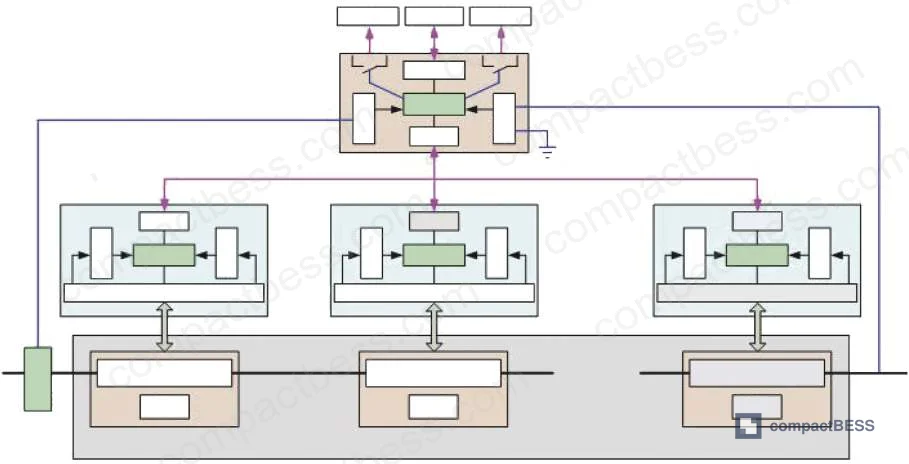
The solution evaluated here replaces all three with a storage-battery-based simulator: a 72-module LiFePO₄ cluster managed by a hierarchical BMS (9 BMUs per cluster, 1 BCU per cluster), paired with a high-efficiency non-isolated bidirectional DC/DC converter. The converter — built around a DSP+FPGA control architecture using SiC power devices — delivers continuously adjustable output from 100 V to 1 000 V with a rated output current of 150 A. It supports constant current, constant voltage, and constant power loading modes.
Honestly, most buyers over-specify the output voltage range on their charger procurement checklist while completely ignoring whether the supplier has validated the charger’s BMS communication stack. The voltage range is table stakes. The communication behavior under fault injection is what separates field-reliable hardware from hardware that passes the spec sheet and fails in deployment.
| Test Method | Voltage Simulation | BMS Protocol Testing | Field Deployable | Fault Injection |
|---|---|---|---|---|
| Pure Resistive Load | ✗ Cannot simulate | ✗ Not possible | ✓ Yes | ✗ Not possible |
| Regenerative Electronic Load | ✓ Partial | ✓ Limited | ✗ Infrastructure constraints | ✓ Limited |
| Real-Vehicle Real-Pile | ✗ Fixed by SoC | ✓ Real BMS | ✓ Yes | ✗ Not controllable |
| LiFePO₄ Battery Simulator (this system) | ✓ 100–1000 V continuous | ✓ Full simulation | ✓ Yes | ✓ Full injection |
The system’s three-layer communication architecture — device layer (BMS interface simulator, battery simulator, waveform recorder), control layer (CAN-based control computer), and data layer (OPC protocol data exchange) — enables automated test execution with no manual intervention after setup.
Insulation Detection and Contactor Timing: Field Test Results #
This is the section that most procurement documents gloss over. Insulation detection behavior and contactor sequencing are where chargers either comply with GB/T 18487.1—2015 or quietly fail — and the failure modes are not always obvious without waveform capture.
Insulation detection voltage compliance
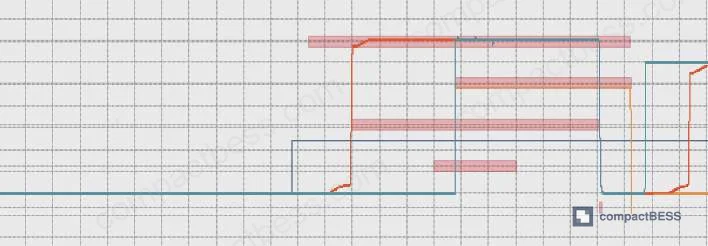
The test system varies the maximum allowable charge voltage declared in the BHM message, then measures actual insulation detection voltage against it. Results:
- When BHM maximum allowable charge voltage = 120.0 V: insulation detection voltage = 0 V (no detection performed — correct, within spec)
- When BHM maximum allowable charge voltage = 350.0 V: detection voltage measured at 351.42 V (deviation: +0.41%)
- When BHM maximum allowable charge voltage = 750 V: detection voltage measured at 751.84 V (deviation: +0.25%)
Both active test points fell within the ±5% tolerance band required by GB/T 18487.1—2015. But this only passed because the charger was tested with a real BMS-driven load. A resistive bench setup cannot vary the BHM voltage declaration — so this compliance point is invisible to standard lab testing.
Low-voltage auxiliary supply
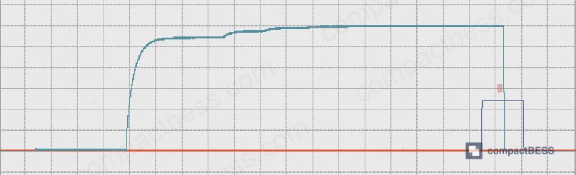
Two test runs measured the low-voltage auxiliary supply circuit. Both runs recorded voltages within the (12 ± 5%) V band required by the standard:
- Run 1: max 12.15 V, min 12.14 V, average 12.15 V — PASS
- Run 2: max 12.17 V, min 12.12 V, average 12.15 V — PASS
Rated auxiliary current: 10 A. Both runs compliant.
Discharge sequencing after insulation check
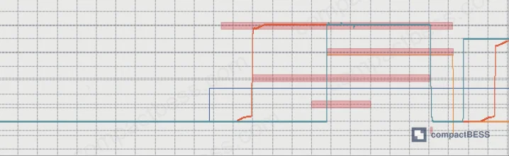
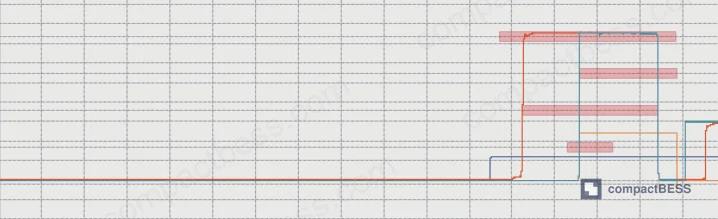
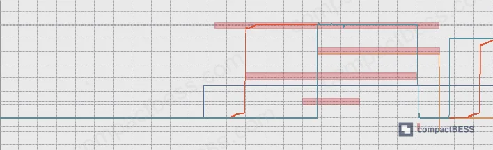
GB/T 18487.1—2015 mandates a specific post-insulation discharge sequence: engage discharge circuit first, then open K1/K2, then stop transmitting CHM messages. Measured timing data:
| BHM Max Voltage (V) | Detection Voltage (V) | K1/K2 Open Time (s) | Voltage Drop to 60 V (s) | CHM Stop Time (s) | Result |
|---|---|---|---|---|---|
| 350.0 | 351.42 | 40.141 | 38.217 | 40.159 | PASS |
| 770.0 | 751.84 | 79.248 | 77.087 | 79.270 | PASS |
In both cases, voltage dropped to 60 V before K1/K2 opened — the correct sequence. The CHM stop timestamp followed K1/K2 opening, as required. These timing relationships are impossible to verify without waveform capture against a live BMS.
Communication Fault Injection: Contactor Response Under Protocol Stress #
Most procurement teams don’t realize that GB/T 34658—2017 — the Chinese standard for EV conductive charging interoperability testing — was specifically structured to require communication fault injection as a mandatory test category, not an optional validation item. Many suppliers either skip this or run it with simplified scripts that don’t fully replicate the three-reconnect timeout sequence.
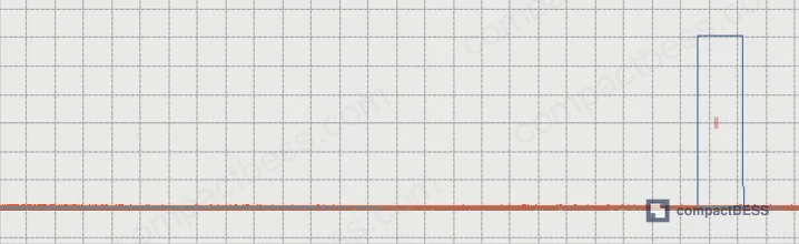
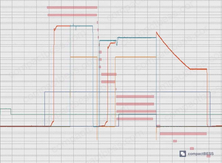
The communication interruption test injects a BMS message stop fault during active constant-voltage charging, then monitors contactor behavior, reconnection attempts, and final state resolution.
Test scenario 1: Communication failure persists after three reconnection attempts
The charger stops receiving BMS messages mid-charge. Test measures contactor response timing and current at disconnect:
- Output voltage at fault: 310.79 V
- Output current at fault: 4.369 A
- Message stop timestamp: 62.509 s
- K1/K2 contactor open time: 63.562 s (1.053 s after message stop — within 10 s requirement)
- K1/K2 disconnect current: 2.439 A
- K3/K4 open time: 85.554 s
- Result: PASS
Test scenario 2: Communication recovers after three reconnection attempts
This scenario is more revealing. After three reconnects, communication recovers and the charger must re-enter the handshake-identification phase and return to normal constant-voltage charging. Timing data across the four-phase sequence:
| Phase | Output Voltage (V) | Output Current (A) | Message Stop (s) | K1/K2 Open (s) | K1/K2 Disconnect Current (A) | K3/K4 Open (s) |
|---|---|---|---|---|---|---|
| Initial charge | 311.04 | 4.390 | 72.397 | 73.573 | 0.098 | — |
| Reconnect 1 | 310.69 | 4.235 | 91.631 | 92.684 | 0.098 | — |
| Reconnect 2 | 310.55 | 4.326 | 110.629 | 111.684 | 0.098 | — |
| Reconnect 3 | 310.86 | 4.330 | 130.833 | 131.888 | 0.084 | 133.405 |
Every reconnection attempt maintained K1/K2 opening within 1.2 seconds of message stop — well within the 10-second window. The K1/K2 disconnect current across all reconnect phases stayed at 0.098 A, significantly below the safety threshold, and the system correctly executed K3/K4 final disconnect at 133.405 s.
In supplier qualification, we’ve seen charger units where the reconnection timer resets incorrectly after the second attempt — meaning the three-reconnect counter never reaches termination, and the charger stays in a persistent soft-fault loop rather than executing a clean disconnect. That failure mode does not show up unless you specifically instrument the CAN bus and measure timestamps across all three reconnect cycles. It passes visual inspection. It passes basic communication tests. It fails in the field.
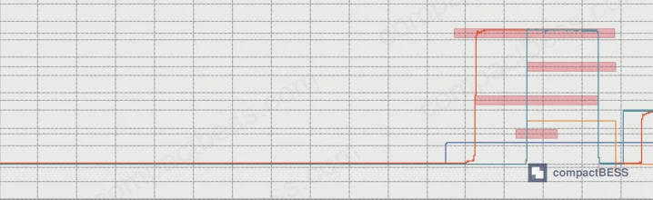
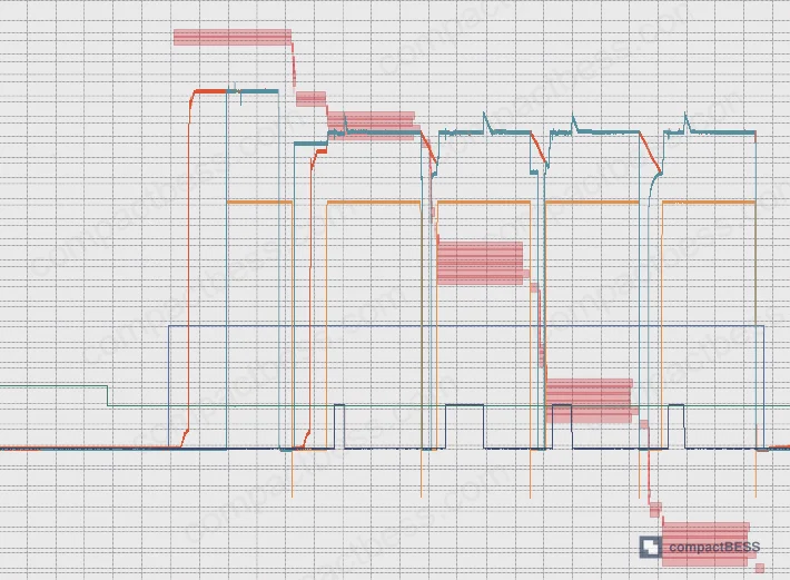
The system architecture behind this testing capability matters for buyers evaluating inverter integration. The bidirectional DC/DC converter topology uses DSP+FPGA control with SiC switching devices — this combination is what enables the fast dynamic response needed to accurately replicate BMS charging curves. Suppliers offering systems built on older IGBT-based converters with single-processor control typically cannot match the response fidelity needed for protocol timing validation.
Practical Guidance for Buyers #
If you’re procuring DC fast chargers, bidirectional inverter modules, or battery simulator equipment for incoming quality inspection, the most expensive mistake is accepting a supplier’s test report without understanding what load was used during testing. A “tested to GB/T 18487.1” claim against a resistive load is almost meaningless for contactor timing and protocol compliance.
The architecture described here — LiFePO₄ storage cluster at 18.4 kWh with hierarchical BMS management across 72 modules — represents the meaningful validation standard for DC charging equipment. Your qualification process should require suppliers to demonstrate insulation detection voltage tracking within ±5% of BHM-declared values, K1/K2 contactor response within 10 seconds of communication loss, and correct three-reconnect sequencing with waveform evidence.
For buyers integrating DC charging stations with energy storage systems — particularly bidirectional V2G-capable installations — protocol interoperability under fault conditions is not a nice-to-have. It is the difference between a system that recovers gracefully from a CAN bus glitch and one that locks up and requires a manual reset on every communication hiccup.
At compactbess.com, we work directly with verified Chinese manufacturers of DC charging systems, bidirectional inverter modules, and BMS components, helping OEM buyers and energy storage integrators across North America, Europe, and the Middle East navigate exactly these technical qualification requirements before committing to a production order. If you’re building a sourcing shortlist for AC/DC charging infrastructure or bidirectional BESS inverter modules, our team can help you identify and pre-screen suppliers against the specific protocol and electrical parameters your application requires.
Need help identifying qualified suppliers for DC charging compatibility testing systems or bidirectional inverter modules? Talk to our sourcing team →
Supplier Qualification Questions #
- Can you provide waveform data showing insulation detection voltage tracking within ±5% of the BHM-declared maximum charge voltage across at least two voltage setpoints (e.g., 350 V and 750 V), tested against a live BMS simulator rather than a resistive load?
- What is the measured K1/K2 contactor opening time after BMS message cessation in your communication interruption test — and can you demonstrate this is consistently within the 10-second window specified by GB/T 18487.1—2015?
- For your three-reconnect communication fault sequence, what are the individual K1/K2 disconnect current values recorded at each reconnect phase, and can you show these remain below 5 A across all attempts?
- Does your battery simulator system support continuous output voltage adjustment from 100 V to 1 000 V at rated 150 A, and can it independently operate in CC, CV, and CP modes — or is mode switching manual and time-limited?
- For the post-insulation discharge sequence, can you provide timestamped waveform evidence that voltage drops to 60 V before K1/K2 opens, and that CHM message transmission stops only after K1/K2 opens — demonstrating compliance with the discharge sequencing requirement in GB/T 18487.1—2015?
Sourcing Checklist #
- [ ] Battery simulator output voltage range covers 100 V to 1 000 V continuously adjustable at rated 150 A output current
- [ ] BMS simulation stack supports full CAN-based protocol exchange including CHM, BHM, CRM, BRM message types for GB/T 34658—2017 interoperability testing
- [ ] Insulation detection voltage verified within ±5% of BHM-declared maximum charge voltage across the charger’s full output range (200–750 V)
- [ ] K1/K2 contactor response to communication loss confirmed ≤10 s, with waveform capture evidence from CAN timestamp logging
- [ ] Low-voltage auxiliary supply validated within (12 ± 5%) V at rated 10 A, verified across two independent test runs
- [ ] Three-reconnect communication fault sequence tested with individual K1/K2 disconnect current measurements at each phase, all documented below 5 A
- [ ] Discharge sequence order confirmed: discharge circuit engages first, K1/K2 opens second, CHM stops third — with timestamped waveform proof
- [ ] DC/DC bidirectional converter uses DSP+FPGA control architecture with SiC power devices (not legacy IGBT-only) for protocol timing fidelity
Key Specifications Table #
| Parameter | Recommended Value | Verification Method |
|---|---|---|
| Battery simulator output voltage range | 100–1 000 V continuous | Measure at both endpoints under rated 150 A load; confirm no gap in adjustment |
| Insulation detection voltage accuracy | Within ±5% of BHM-declared max charge voltage | Set BHM to 350 V and 750 V; measure DetectU via waveform recorder; calculate deviation |
| K1/K2 contactor response to comm loss | ≤10 s from message cessation | Inject BMS stop fault via CAN; timestamp from last valid packet to K1/K2 open event |
| Low-voltage auxiliary supply | (12 ± 5%) V = 11.4–12.6 V at 10 A | Two-run test; record max, min, average; both runs must stay within band |
| Three-reconnect sequence K1/K2 disconnect current | <5 A at each disconnect event | Waveform capture during all four phases; flag any event exceeding threshold |
| Post-insulation voltage discharge to 60 V | Must precede K1/K2 opening | Compare DetectU timestamp at 60 V vs. K1/K2 open event timestamp |
| Output current rated | 150 A | Sustained output at 150 A across full voltage range; thermal imaging after 30-minute hold |
Can’t find a supplier meeting these specs? Submit your requirements and we’ll match you within 48 hours.
References #
Data source: Field Evaluation of DC Charging Compatibility Testing Using Energy Storage Battery Simulators for Non-Vehicle Charger Validation, Y. Wang et al., Journal of the Electrochemical Society, 2024
Frequently Asked Questions #
Why can’t a pure resistive load be used to test DC charger compliance with GB/T 18487.1—2015?
Resistive loads are passive — they cannot simulate battery voltage, respond to BMS protocol messages, or replicate the dynamic charging curve of a real pack. Critical compliance checks like insulation detection voltage tracking (which must match the BHM-declared maximum charge voltage within ±5%) and contactor timing under communication faults are simply invisible to resistive load testing. A charger can pass a resistive-load acceptance test and still fail every protocol-level compliance point.
What does “three-reconnect” behavior mean in DC charging protocol compliance?
When BMS communication is interrupted during charging, the standard requires the charger to attempt reconnection three times before executing a final disconnect. Each reconnect attempt must correctly re-enter the handshake-identification phase. If the charger fails to count reconnects correctly, or fails to execute a clean K3/K4 disconnect after the third failure, it is non-compliant — regardless of steady-state electrical performance. The test data here shows correct sequencing with K3/K4 final disconnect at 133.405 s after the third reconnect attempt.
What LiFePO₄ pack configuration was used in the reference test system?
The system used 72 F80 battery modules connected in series, forming an 18.4 kWh cluster at 230 V nominal and 80 Ah. Each group of 12 cells was managed by one BMU; 9 BMUs per cluster were overseen by a single BCU. This hierarchical structure — BCU managing all BMUs — is representative of grid-scale BESS management architecture and is worth referencing when evaluating BMS designs for similar applications. See our BMS communication protocols guide for more on BCU/BMU hierarchies.
What is the significance of the K1/K2 disconnect current staying at 0.098 A across reconnect phases?
At 0.098 A, K1/K2 is disconnecting under essentially zero-current conditions — this is the desired behavior, as it minimizes contact arcing and extends contactor service life. The comparison case (persistent fault scenario) showed a K1/K2 disconnect current of 2.439 A — still within acceptable limits, but meaningfully higher. For buyers specifying systems with high cycle counts, low disconnect current under fault conditions directly affects contactor replacement intervals and long-term maintenance cost.
Which internal standards are most relevant when sourcing DC charging equipment for cross-border projects?
For DC charging equipment sold into markets where Chinese-manufactured chargers must meet both domestic and international requirements, ORGID,FSPAPEXPAGE,FSPPROJECTID:1276,23,20486″ target=”_blank” rel=”nofollow noopener”>IEC 62196-3 (connector and inlet configurations) are the primary references alongside GB/T 18487.1. For AC charging integration, see our AC charging and inverter integration documentation.
Published by compactbess.com Technical Team | Request a sourcing quote


