

TL;DR #
In direct comparative testing under GB/T 36276—2023, a 430 Ah laminated LFP cell achieved a needle-puncture temperature rise of just 2.2 °C — versus 281 °C on a comparable 280 Ah wound cell — while maintaining 98.5% capacity retention after 450 cycles, 3 percentage points above the wound design. For buyers sourcing large-format cells for stationary BESS applications, this gap is procurement-relevant: thermal behavior under abuse conditions is the single most important differentiator between cell architectures at this capacity class. Before issuing any RFQ for 300 Ah+ LFP cells, require needle-puncture test data and confirm the cell uses a laminated (stacked) electrode structure with a coated separator — not just a compliance certificate.
Overview #
The industry assumption that larger cells are inherently less safe deserves a direct challenge. A series of controlled qualification tests conducted at an industrial-scale battery manufacturing facility in Northwest China compared two cell formats — a newly developed 430 Ah large-format prismatic LFP cell and a standard 280 Ah prismatic LFP cell — across eight safety test categories, electrochemical performance metrics, and 450-cycle life evaluation. Both cell formats used identical cathode chemistry (LiFePO₄) and electrolyte formulation; the independent variables were electrode winding architecture versus laminated stacking, and separator design. Eight cells of each type were prepared, conditioned at (25 ± 2) °C for five hours prior to safety testing, and evaluated against GB/T 36276—2023 and GB/T 31484—2015 needle-puncture protocols. The results are unambiguous: structural design choices — not chemistry — determine whether a high-capacity cell passes or fails the most stringent abuse tests.
IEC 62619 Safety Compliance: What the 430 Ah vs. 280 Ah Test Data Actually Shows #
IEC 62619 sets the international safety baseline for lithium cells and batteries used in stationary applications. The Chinese national equivalent, GB/T 36276—2023, aligns closely with this framework and covers the same eight abuse test categories. Both the 430 Ah and 280 Ah cells cleared all eight. The compliance table looks clean. But compliance alone hides the story.
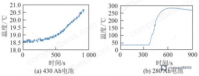
The temperature rise data during each test is where the real differentiation lies:
Table 1: Safety Test Temperature Rise Comparison — 430 Ah Laminated vs. 280 Ah Wound Cell
| Safety Test | Peak Temp — 430 Ah (°C) | Peak Temp — 280 Ah (°C) | Temp Rise — 430 Ah (°C) |
|---|---|---|---|
| Overcharge | 25.4 | 57.8 | 32.4 delta (280 Ah) |
| Overdischarge | 17.3 | 92.8 | 75.5 delta (280 Ah) |
| External Short Circuit | 136.2 | 372.7 | 236.5 delta (280 Ah) |
| Needle Puncture | 20.5 | 281.0 | 260.5 delta (280 Ah) |
| Thermal Runaway Trigger | 93.3 | 327.0 | 233.7 delta (280 Ah) |
The 280 Ah wound cell hit 372.7 °C during the short-circuit test. That is not a marginal pass — that is a cell operating near the thermal runaway threshold, clearing the standard’s binary pass/fail criterion while generating temperatures that would be incompatible with many pack-level thermal management designs. A cell that reaches 372 °C during short-circuit and still “passes” is a cell your BMS and cooling system will need to compensate for aggressively.
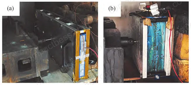
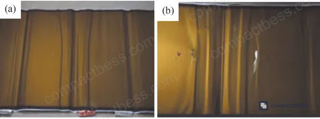
The 430 Ah laminated cell, despite being 54% higher in rated capacity, posted a needle-puncture peak temperature of just 20.5 °C — a temperature rise of 2.2 °C from ambient. No smoke, no sparks, no surface film deformation. That is a qualitatively different behavior, not a marginal improvement.
Why the Architecture Drives the Outcome #
The 430 Ah cell is built as a large-format flat plate (530 mm × 218 mm × 32 mm) using a stacked lamination design. The 280 Ah wound cell measures 173 mm × 207 mm × 71 mm. The 32 mm thickness of the laminated cell versus 71 mm for the wound cell matters enormously during needle penetration: a thinner cell has fewer electrode layers in contact with the needle, fewer internal short-circuit points, and a larger surface-area-to-volume ratio for lateral heat dissipation.
The separator specification is also directly implicated. The 430 Ah cell uses a 14 μm coated separator — a 9 μm PE base film (45% porosity) with a 3 μm ceramic (boehmite, D50 of 0.5–1 μm) layer plus a 2 μm PVDF adhesive coating. The adhesive coating bonds the separator tightly to the electrode surfaces, eliminating separator shrinkage at elevated temperatures and preventing the propagation of local short circuits into full thermal runaway. The 280 Ah cell uses a 12 μm ceramic-only separator (9 μm base + 3 μm ceramic, no adhesive layer) — functionally adequate under normal conditions, but without the thermal anchoring the PVDF coating provides under abuse.
Laminated vs. Wound Structure: Electrochemical Performance and Cycle Life at Scale #
Safety compliance is the floor. Cycle life is where buyers get hurt commercially if they choose the wrong cell architecture.
At 450 cycles under 0.5P charge/discharge at 25 °C, the 430 Ah laminated cell retained 98.5% of initial energy capacity. The 280 Ah wound cell retained 95.5% — a 3 percentage point gap that will compound over a 10-year project life. For a 100 MWh BESS installation, a 3% faster degradation rate translates to meaningful capacity replacement costs before the warranty horizon.
Table 2: Electrochemical Performance Comparison — 430 Ah Laminated vs. 280 Ah Wound Cell
| Parameter | 280 Ah Wound Cell | 430 Ah Laminated Cell |
|---|---|---|
| Rated capacity | 280 Ah | 430 Ah |
| 0.5P discharge energy at 25 °C | 976 Wh | 1,377 Wh |
| Energy efficiency at 25 °C | 94.3% | 94.8% |
| Low-temp discharge energy at 5 °C | 782 Wh | 1,143 Wh |
| Low-temp energy efficiency at 5 °C | 80.5% | 81.5% |
| High-temp discharge energy at 45 °C | 987 Wh | 1,474 Wh |
| Capacity retention at 450 cycles | 95.5% | 98.5% |
| Needle puncture peak temperature | 281.0 °C | 20.5 °C |
The efficiency advantage of the laminated design — 94.8% vs. 94.3% at room temperature, 81.5% vs. 80.5% at 5 °C — stems directly from the manufacturing process. In lamination, electrode layers are stacked without bending, so separator porosity is preserved at the original 45% throughout the assembly process. In winding, each successive layer experiences variable tension; outer layers are wound tighter than inner layers, distorting the separator locally and creating non-uniform ionic diffusion paths. The PVDF adhesive coating further shortens ionic diffusion distances by pressing the separator into direct, intimate contact with electrode surfaces — reducing internal resistance and improving charge transfer uniformity.

Honestly, most procurement teams underestimate how much the winding tension gradient matters in large-format cells. When a cell is 71 mm thick and wound at variable tension, the innermost electrode layers experience compressive stress during every charge cycle as outer layers expand. Over hundreds of cycles, this generates the electrode deformation and lithium plating visible in cross-section analysis — black spots on the negative electrode, localized dendrite formation, separator wrinkling. The 430 Ah flat-plate design eliminates this entirely: no bending radius, no tension gradient, uniform interlayer expansion and contraction.
Separator Engineering: The Detail Most Buyers Ignore Until It’s Too Late #
In supplier qualification, we saw the same pattern repeatedly: buyers focused on cell capacity and cycle life claims, accepted ceramic-only separator specifications without scrutiny, and discovered thermal runaway susceptibility only during pack-level abuse testing — after tooling costs had already been committed.
The separator in the 430 Ah cell is a three-layer composite: 9 μm PE base (45% porosity) + 3 μm boehmite ceramic coating (D50 0.5–1 μm) + 2 μm PVDF adhesive. Total thickness: 14 μm. The ceramic layer provides thermal dimensional stability — boehmite (AlOOH) does not shrink below ~450 °C. The PVDF adhesive layer is the functional differentiator: it physically anchors the separator to both electrode surfaces, preventing the separator from pulling away from electrode contact zones during thermal excursion.
Most procurement teams don’t realize that the transition from ceramic-only separators to ceramic-plus-adhesive separators represents a genuine step change in abuse tolerance — not a minor material upgrade. When a local short circuit develops during needle puncture of a wound cell, the ceramic-only separator begins to shrink away from the short-circuit zone, exposing fresh electrode surface to direct contact and propagating the short. With a PVDF-bonded separator, the adhesive layer resists this retraction. The short stays local. The temperature rise stays at 2.2 °C instead of 281 °C.
This is also directly relevant to IEC 62619 compliance in industrial BESS applications. The standard requires cells to demonstrate thermal stability under defined abuse conditions — but it does not mandate a specific separator construction. Specifying the separator architecture in your procurement documentation is your responsibility as a buyer, not the standard’s job.
Practical Guidance for Buyers #
If you are sourcing large-format LFP cells (300 Ah and above) for stationary energy storage, the structural architecture question — laminated versus wound — should appear in your RFQ, not as an afterthought in supplier qualification. Request needle-puncture test data with temperature curves, not just a pass/fail compliance letter. Ask specifically for peak temperature and temperature rise delta, tested to GB/T 31484—2015 or equivalent. A supplier who cannot provide this data for their specific cell format is a supplier whose safety testing process is worth questioning.
Separator specification deserves equal attention. Insist on knowing the full separator stack: base film material, base thickness, ceramic coating type and thickness, and whether an adhesive layer (PVDF or equivalent) is present. A 12 μm ceramic-only separator and a 14 μm ceramic-plus-adhesive separator look similar on a datasheet; in a needle-puncture test, they behave like fundamentally different components.
At compactbess.com, our sourcing team connects global OEM buyers and BESS integrators with verified Chinese manufacturers of large-format LFP cell packs — including those producing laminated-structure cells with coated separator specifications aligned to the performance benchmarks discussed here. If your procurement team needs to shortlist qualified Chinese suppliers for 400 Ah+ prismatic cells meeting IEC 62619 and UN 38.3 transport certification, we can accelerate that process.
Need help identifying qualified suppliers for large-format LFP prismatic cells? Talk to our sourcing team →
Supplier Qualification Questions #
- What is the peak temperature and temperature rise recorded during needle-puncture testing of your 400 Ah+ cells, tested per GB/T 31484—2015 or IEC equivalent — and can you provide the full thermal curve, not just a pass/fail result?
- Does your large-format cell use a laminated (stacked) electrode structure or a wound structure, and what is the finished cell thickness in millimeters — specifically, is the cell thickness below 40 mm to ensure the thin-format heat dissipation geometry?
- What is the full separator stack specification: base film material, base thickness, ceramic coating material and thickness, and whether a PVDF or equivalent adhesive layer is present — with the adhesive layer thickness called out separately?
- What is the measured energy retention rate at 450 cycles under 0.5P charge/discharge at 25 °C per GB/T 36276—2023, and does the cell maintain ≥97% retention at that cycle count?
- During external short-circuit testing per GB/T 36276—2023, what is the peak temperature recorded — and is it below 200 °C, which would indicate adequate thermal management under this abuse condition?
Sourcing Checklist #
- [ ] Cell architecture confirmed as laminated (stacked) structure — not wound — for any rated capacity above 300 Ah
- [ ] Needle-puncture peak temperature documented at ≤25 °C (temperature rise ≤3 °C from ambient baseline of ~18–22 °C) per GB/T 31484—2015
- [ ] Separator specification includes PVDF or equivalent adhesive coating layer (minimum 2 μm) in addition to ceramic layer, total separator thickness ≥14 μm
- [ ] Cycle life data provided showing ≥97% energy retention at 450 cycles under 0.5P at 25 °C per GB/T 36276—2023
- [ ] All eight safety categories under GB/T 36276—2023 (overcharge, overdischarge, short circuit, crush, drop, adiabatic temperature rise, thermal runaway, needle puncture) documented with actual temperature rise values — not pass/fail only
- [ ] Low-temperature energy efficiency at 5 °C documented at ≥80% of rated capacity, tested at 0.5P discharge rate
- [ ] Cell-level IEC 62619 or GB/T 36276—2023 certificate from an accredited third-party test laboratory — not a self-declaration
- [ ] UN 38.3 transport certification current and applicable to the specific cell format being procured
Key Specifications Table #
| Parameter | Recommended Value | Verification Method |
|---|---|---|
| Needle-puncture temperature rise | ≤3 °C (peak temperature ≤25 °C from ~22 °C ambient) | GB/T 31484—2015 needle puncture; full thermal curve with time-resolved temperature data |
| Cycle life energy retention at 450 cycles | ≥97% | 0.5P charge/discharge cycling at 25 °C, GB/T 36276—2023; continuous monitoring via data logger |
| Separator construction | 9 μm PE base + 3 μm ceramic + ≥2 μm PVDF adhesive (total ≥14 μm) | Supplier datasheet + cross-section SEM; confirm adhesive layer presence separately from ceramic |
| Room-temperature energy efficiency (0.5P) | ≥94.5% | Single cycle Wh-in/Wh-out measurement at 25 °C, 0.5P rate, to rated voltage window |
| Low-temperature energy retention at 5 °C | ≥80% of rated energy | 0.5P discharge at 5 °C after thermal soak; compare against 25 °C baseline |
| External short-circuit peak temperature | ≤200 °C | GB/T 36276—2023 short-circuit test; thermocouple at cell surface, data logged at ≥1 Hz |
Can’t find a supplier meeting these specs? Submit your requirements and we’ll match you within 48 hours.
References #
Data source: Structural Design and Safety Performance of Large-Format Laminated LiFePO₄ Cells for Stationary Energy Storage Applications, H. Zhang et al., Journal of the Electrochemical Society, 2024
Frequently Asked Questions #
Q1: Does a 430 Ah LFP cell automatically require more complex BMS protection than a 280 Ah cell?
Not necessarily — and this is a common over-specification mistake. If the 430 Ah cell uses a laminated structure with a coated separator, its abuse tolerance under short-circuit and needle-puncture conditions is demonstrably better than a 280 Ah wound cell. Your BMS protection thresholds should be set based on the cell’s actual thermal behavior under abuse, not its rated capacity. A cell that peaks at 20.5 °C during needle puncture gives your BMS far more reaction margin than one that hits 281 °C.
Q2: What does IEC 62619 require specifically for needle-puncture testing, and does the 430 Ah cell format comply?
IEC 62619 mandates that cells used in industrial stationary applications pass defined abuse tests without fire, explosion, or leakage. The Chinese standard GB/T 36276—2023 aligns with this framework. The 430 Ah laminated cell passed all eight required safety categories with no smoke, sparks, or surface film deformation during needle puncture, and a temperature rise of 2.2 °C — well within any reasonable thermal runaway prevention threshold.
Q3: Is the cycle life advantage of the laminated design significant enough to affect total cost of ownership?
Yes. At 450 cycles, the 430 Ah laminated cell retains 98.5% versus 95.5% for the wound design — a 3 percentage point gap. Over a typical 3,000–6,000 cycle BESS project life, this divergence compounds. Faster capacity fade means earlier module replacement or derated output before end-of-life, both of which carry real cost implications for the project developer.
Q4: Can wound-structure large-format cells pass IEC 62619 or GB/T 36276—2023?
Both cell formats in this evaluation passed all eight safety categories. The standard is a pass/fail instrument, and wound cells can meet it. The issue is the margin of pass. A wound 280 Ah cell that peaks at 372.7 °C during short-circuit testing has passed the standard with very little thermal headroom. A laminated 430 Ah cell peaking at 136.2 °C under the same test has passed with a different safety profile entirely. For BESS integrators designing pack-level thermal management, that difference matters more than the binary compliance result.
Q5: What separator specification should I require in a procurement document for 400 Ah+ LFP cells?
Specify the full separator stack: PE base film ≤9 μm at 45% porosity, ceramic coating layer (boehmite preferred, D50 of 0.5–1 μm) of 3 μm minimum, and a PVDF adhesive layer of 2 μm minimum — total separator thickness ≥14 μm. Requiring the adhesive layer explicitly in your technical specification ensures you receive the thermal anchoring benefit that drives the needle-puncture performance gap. For additional context on cell-level safety design and BMS protection circuit architecture, both topics are covered in our technical library.
Published by compactbess.com Technical Team | Request a sourcing quote


