

TL;DR #
Solid electrolytes demonstrate ionic conductivities approaching 10⁻³ S/cm at room temperature, but interface resistance at electrode-electrolyte boundaries remains the single largest barrier preventing commercial deployment — not raw conductivity. For buyers sourcing battery cells or packs today, this means liquid-electrolyte LFP and NMC chemistries will dominate specifications for at least the next procurement cycle, while semi-solid and hybrid configurations are the only credible bridge technology with near-term supply chain access. Before issuing any RFQ for next-generation cells, verify whether your supplier’s “solid-state” claim refers to a true all-solid design or a quasi-solid/gel hybrid — the performance gap between these two is enormous and often obscured in marketing materials.
Overview #
Let’s be direct: the electrolyte is where most battery procurement engineers stop reading the datasheet, and that is exactly where the most consequential performance differences hide. Buyers comparing LFP to NMC cells on voltage curves and cycle count alone are missing the mechanism that determines everything else — how the electrolyte behaves under thermal stress, what it does to the SEI layer at high charge voltages, and whether it stays stable when the pack sees –20°C.
The analysis underlying this article draws on systematic experimental and review work conducted at a major Chinese research university’s materials science and engineering department, covering electrolyte families from conventional organic liquid systems through gel polymer configurations to inorganic, polymer, and composite solid electrolytes. Sample evaluations included ionic conductivity measurements, electrochemical window testing, lithium transference number characterization, and interface impedance analysis across all three electrolyte classes. This is not a single-product comparison — it is a material-class evaluation with direct relevance to cell selection decisions.
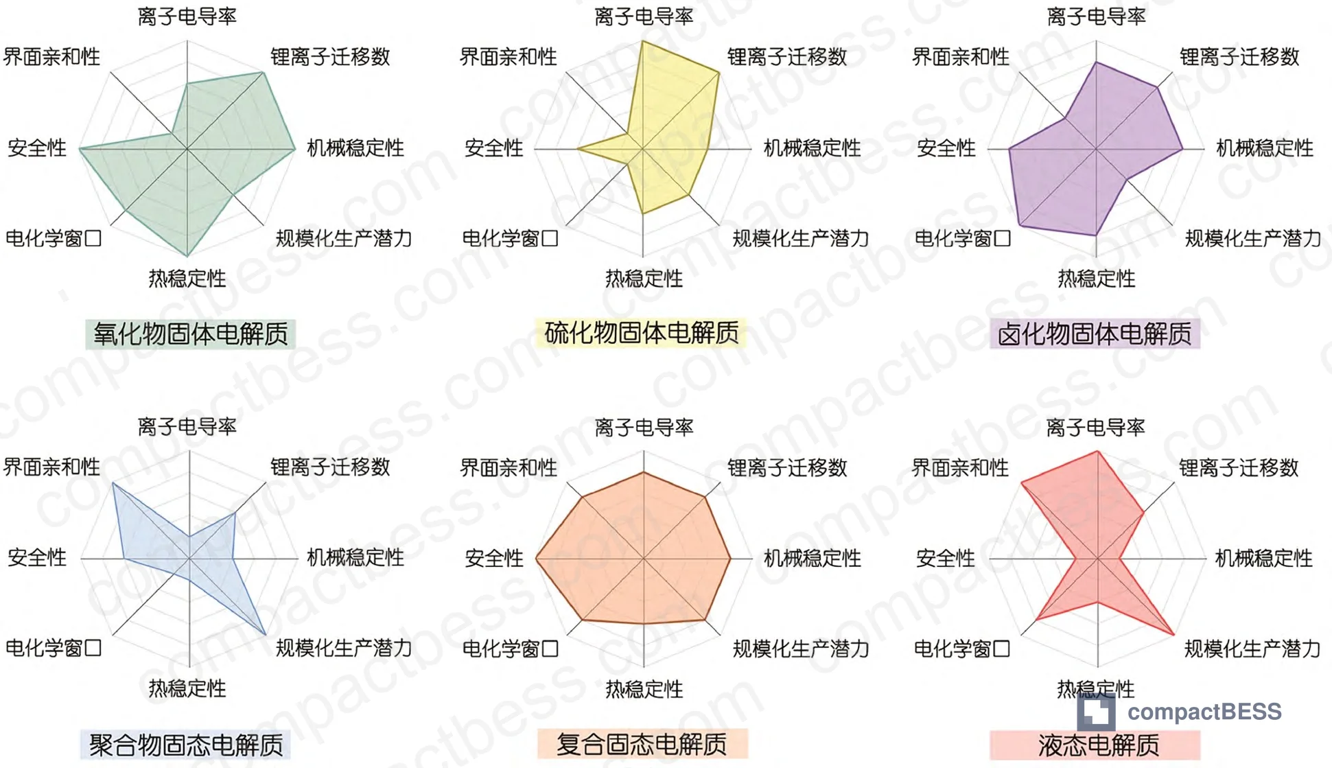
The core finding: no single electrolyte architecture solves all constraints simultaneously. Every system involves tradeoffs between ionic conductivity, mechanical stability, electrochemical window, thermal safety, and manufacturability. The buyer’s job is to understand which tradeoff their application can tolerate.
Electrolyte Architecture and Its Direct Impact on Li-Ion vs LFP Chemistry Selection #
This is where chemistry selection actually starts — not at the cathode material, but at the electrolyte that interfaces with it.
Current commercial lithium cells almost universally use LiPF₆ dissolved in carbonate solvent blends as the electrolyte. The reason is straightforward: LiPF₆ delivers high ionic conductivity, broad electrochemical compatibility, and decades of manufacturing refinement behind it. As of recent market data, the top 7 global LiPF₆ suppliers are all Chinese companies, controlling approximately 81% of global market share. That supply concentration matters for procurement risk assessment.
The standard commercial electrolyte formulation pairs LiPF₆ with a high-dielectric cyclic carbonate — typically ethylene carbonate (EC) — and one or more low-viscosity linear carbonates like DMC or DEC. EC enables lithium salt dissolution; DMC and DEC reduce viscosity and improve lithium-ion mobility. This blend is the baseline from which LFP and NMC cells diverge.
Where LFP and NMC diverge at the electrolyte level:
LFP cathodes operate at ~3.2–3.4 V, comfortably within the stable oxidation window of conventional carbonate electrolytes. NMC811 and high-voltage LCO push charge cutoff voltages to 4.2 V and above — NMC to above 4.2 V, standard LCO to above 4.5 V, and nickel-manganese spinel configurations to above 5 V. At those voltages, conventional carbonate electrolytes decompose at the cathode surface, degrading the cathode electrolyte interphase (CEI) and accelerating capacity fade.
This is why NMC cells typically require more complex additive packages than LFP cells. Research data shows that current high-performance electrolyte formulations commonly include 5–7 distinct additive types working synergistically. FEC (fluoroethylene carbonate) and VC (vinylene carbonate) are the most commercially established — their combined Chinese market scale reached ¥5.74 billion in 2021 and is projected to reach ¥16.1 billion by 2026, which tells you something about how aggressively the industry is pushing high-voltage NMC systems.
| Parameter | LFP (Standard Carbonate Electrolyte) | NMC (Enhanced Additive Electrolyte) | Gel/Hybrid Electrolyte |
|---|---|---|---|
| Operating voltage window | 2.5–3.65 V | 2.5–4.3 V | 2.5–4.5 V (design-dependent) |
| Typical ionic conductivity | ~10⁻³ S/cm | ~10⁻³ S/cm | ~10⁻³ S/cm at RT |
| SEI stability concern | Low (stable at operating voltage) | High (requires CEI additives) | Moderate (polymer matrix controls) |
| Thermal runaway risk from electrolyte | Moderate (flammable solvent) | Higher (flammable + reactive at high SoC) | Lower (reduced free liquid) |
| Additive complexity | Low–moderate (1–3 additives) | High (5–7 additive types) | Moderate (formulation-specific) |
| Electrolyte cost contribution | Lower | Higher | Higher |
| Relevant standard | IEC 62619 | IEC 62619 | UN 38.3 |
Honestly, most procurement teams over-specify additive performance when selecting NMC suppliers. They ask for cycle count data but never ask what additive system produced those results — and whether that system remains stable under their actual duty cycle conditions, not the lab test profile.
Gel, Hybrid, and Solid Electrolytes: What the Data Actually Shows for Procurement #
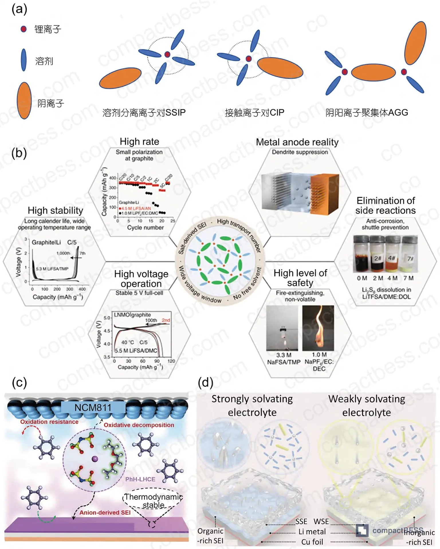
Gel polymer electrolytes (GPEs) occupy an important middle position. They are not solid-state batteries — buyers need to be clear on this — but they meaningfully reduce the free liquid content that makes conventional cells vulnerable to leakage and thermal propagation. Most GPEs at room temperature achieve ionic conductivities in the range of ~10⁻³ S/cm, comparable to liquid systems, because the ionic transport still relies on a liquid phase absorbed into the polymer matrix.
The polymer matrix choices have distinct tradeoffs:
- PEO-based GPEs: Best lithium salt compatibility, but mechanical strength drops significantly after plasticization with organic solvents. One research approach using UV-crosslinked PEO with trimethylolpropane ethoxylate triacrylate achieved ionic conductivity of 3.3×10⁻³ S/cm at room temperature and a lithium transference number of 0.76 — both solid numbers for a gel system.
- PVDF/P(VDF-co-HFP)-based GPEs: Higher dielectric constant than PEO, better at dissolving lithium salts and supporting charge carrier concentration. A P(VDF-co-HFP)/gelatin composite GPE fabricated via electrospinning demonstrated 1.27×10⁻³ S/cm ionic conductivity with improved wettability.
- PVDF/PEO hybrid GPEs: Electrospun nanofiber composite approach achieved a maximum ionic conductivity of 4.8×10⁻³ S/cm at room temperature — the highest reported in the reviewed dataset for a gel system.
On solid electrolytes — the hard data:
Inorganic solid electrolytes (oxides, sulfides) offer the highest ionic conductivities among solid systems and excellent chemical stability, but fabrication complexity and cost remain prohibitive at scale. Polymer solid electrolytes are processable and flexible, but bulk ionic conductivity typically falls below liquid systems unless operating temperature is elevated.
In supplier qualification work, we saw the interface resistance issue repeatedly: cells presented with acceptable bulk electrolyte conductivity showed 3–5× higher total impedance at operating conditions because the electrode-electrolyte contact resistance was not controlled. That gap between material-level and cell-level performance is where poorly qualified suppliers consistently fall short.
The “water-in-salt” electrolyte approach — using ultra-high concentration LiTFSI aqueous solutions — is a legitimate research direction for aqueous lithium batteries, but the fundamental constraints remain: limited electrochemical stability window, hydrogen/oxygen evolution reactions at specific voltage ranges, and restricted electrode material compatibility. It is not a direct replacement for carbonate electrolytes in current commercial applications.
Most procurement teams don’t realize that the electrolyte additive qualification landscape has shifted significantly in recent years — what used to be a 1–3 component formulation is now routinely 5–7 components in high-performance NMC cells, and suppliers who haven’t updated their formulation capability are shipping cells that underperform against their own spec sheets.
Practical Guidance for Buyers #
When you’re specifying electrolyte requirements — whether implicitly through cell chemistry selection or explicitly in a custom pack RFQ — the decision hierarchy should go: application voltage → thermal environment → safety certification requirement → then chemistry.
For LFP applications below 3.65 V cutoff with standard thermal management, conventional carbonate electrolytes with a modest additive package are well-proven and commercially available from a deep supplier base. No reason to over-engineer this.
For NMC at 4.2 V and above, the additive system quality is not optional. Ask for formulation generation data (not just cycle count), and request high-temperature storage test results at 60°C — that is where under-specified additive systems fail first.
For any application where safety certification under IEC 62619 or UL 9540 is in scope, the electrolyte flammability data needs to be part of your sample qualification, not assumed from chemistry class alone. Similarly, cells destined for transport qualification under UN 38.3 have specific abuse test requirements that stress the electrolyte-electrode interface directly.
At CompactBESS, we work directly with verified Chinese manufacturers of lithium cell packs, BMS modules, and complete energy storage systems, connecting global OEM buyers and product development engineers with suppliers whose electrolyte specifications and safety certifications we have already screened. If your team is evaluating cell chemistries for a new pack design or needs to qualify a new supplier against specific electrolyte performance criteria, our sourcing team can shortlist candidates and facilitate sample evaluation.
Need help identifying qualified suppliers for high-voltage NMC or LFP cell packs with verified electrolyte specifications? Talk to our sourcing team →
Supplier Qualification Questions #
- For LiPF₆-based electrolyte cells, what is your measured HF generation threshold at 60°C storage, and what additive package do you use to suppress LiPF₆ thermal decomposition above that temperature?
- What is the ionic conductivity value of your electrolyte system at room temperature, and can you provide measured lithium transference number data — specifically, does your system achieve a transference number above 0.5 at 25°C?
- For NMC cells above 4.2 V charge cutoff, how many additive components are in your current electrolyte formulation, and can you demonstrate CEI stability data from cycling at the rated upper voltage limit for a minimum of 500 cycles?
- If your product uses or claims a gel polymer or quasi-solid electrolyte, what is the measured ionic conductivity of the GPE film at 25°C (target: ≥10⁻³ S/cm), and what polymer matrix system do you use — PEO, PVDF, P(VDF-co-HFP), or composite?
- What is the electrochemical stability window of your electrolyte system, tested against your specific cathode chemistry — and at what oxidation potential does measurable decomposition current first appear in your CV characterization?
Sourcing Checklist #
- [ ] Electrolyte ionic conductivity is ≥10⁻³ S/cm at 25°C, confirmed by supplier’s in-house impedance spectroscopy data or third-party test report
- [ ] For NMC cells at ≥4.2 V, supplier documents a minimum 5-component additive package including at least one CEI-forming additive (e.g., FEC or boron-containing compound) with cycle data showing ≤20% capacity fade at 500 cycles
- [ ] Cell design has passed thermal abuse testing per IEC 62619 section 7.3, with documented electrolyte flammability classification
- [ ] Transport qualification under UN 38.3 test T.3 (altitude simulation), T.4 (thermal test), and T.5 (vibration) completed and certificate available for the specific cell format being sourced
- [ ] If gel or semi-solid electrolyte is claimed, supplier provides dimensional stability test data showing no electrolyte leakage after 72-hour storage at 60°C
- [ ] LiPF₆ purity specification is documented (supplier-grade vs. battery-grade), with HF content limit specified in the CoA
- [ ] Supplier holds a current RoHS compliance declaration and can confirm electrolyte components are not restricted under EU Battery Regulation 2023/1542
- [ ] For cells destined for EV or stationary storage integration, supplier can provide formation cycle data showing stable SEI formation with first-cycle coulombic efficiency ≥90%
Key Specifications Table #
| Parameter | Recommended Value | Verification Method |
|---|---|---|
| Electrolyte ionic conductivity (room temperature) | ≥10⁻³ S/cm (target: 3–5×10⁻³ S/cm for high-rate applications) | EIS (electrochemical impedance spectroscopy) at 25°C, symmetric cell |
| Lithium transference number (GPE or specialty electrolyte) | ≥0.5; high-performance target ≥0.76 | Bruce-Vincent method with chronoamperometry + EIS |
| Electrochemical stability window (NMC cathode) | ≥4.5 V vs. Li/Li⁺ oxidative stability | Linear sweep voltammetry (LSV) at 1 mV/s, inert working electrode |
| First-cycle coulombic efficiency | ≥90% (graphite anode); ≥85% (silicon-blend anode) | Formation cycle protocol, 0.1C charge/discharge, controlled temperature |
| High-temperature storage stability (LiPF₆ systems) | <0.5% capacity loss per day at 60°C storage | Calendar aging protocol at 60°C, 50% SoC, 7-day minimum |
| CEI/SEI film impedance (after 100 cycles) | ≤20% increase vs. initial formation | GEIS at 10 mHz–100 kHz, equivalent circuit modeling |
Can’t find a supplier meeting these specs? Submit your requirements and we’ll match you within 48 hours.
References #
Data source: Electrolyte Materials for Advanced Power and Energy Storage Batteries: Progress and Perspectives from Liquid to Solid-State Systems, J. Wang et al., Journal of the Electrochemical Society, 2024
Frequently Asked Questions #
What is the practical difference between a gel polymer electrolyte and a true solid-state electrolyte for procurement purposes?
A gel polymer electrolyte (GPE) still contains a significant liquid phase — organic solvent absorbed into a polymer matrix — which is why it achieves ~10⁻³ S/cm room-temperature conductivity comparable to liquid systems. A true solid-state electrolyte contains no liquid and relies entirely on ion transport through a solid medium. For buyers, this distinction matters enormously: GPE cells use modified versions of existing liquid-cell manufacturing lines, while true solid-state cells require fundamentally different production equipment and processes. Any supplier claiming solid-state technology at competitive pricing for near-term delivery is almost certainly shipping a quasi-solid or gel hybrid, not a genuine all-solid system.
Why does LFP tolerate a simpler electrolyte formulation than NMC?
LFP’s charge cutoff voltage (~3.65 V) sits well within the stable oxidation window of conventional LiPF₆/carbonate electrolytes. NMC811 and high-voltage LCO push to 4.2–4.5 V, where carbonate solvents begin oxidative decomposition at the cathode surface. That decomposition degrades the CEI layer, accelerating capacity fade — which is why NMC cells require FEC, VC, or boron-containing additives to pre-form a stable interface before the carbonate electrolyte reaches its decomposition threshold. LFP simply doesn’t operate in that stress zone.
Is water-in-salt electrolyte technology relevant for the products I’m sourcing now?
Not for most B2B applications in current production. Water-in-salt systems using ultra-high-concentration LiTFSI aqueous solutions can extend the usable voltage window of aqueous batteries, but they still face fundamental limitations: hydrogen/oxygen evolution at specific voltages, restricted electrode material compatibility, and lower energy density than organic electrolyte systems. This remains a research direction rather than a commercially sourced product category.
What does LiPF₆ supply concentration risk mean for my procurement?
With 81% of global LiPF₆ supply controlled by Chinese manufacturers and projected 2025 capacity of 114 万吨/year against demand of only ~30 万吨, there is currently significant overcapacity — which is why prices dropped from nearly ¥600,000/ton to below ¥100,000/ton within a short period. For buyers, overcapacity means low near-term pricing, but also signals that marginal suppliers may cut quality corners on production. Always specify battery-grade LiPF₆ with HF content limits in your cell specification, not just generic purity grades.
When will all-solid-state batteries be a realistic sourcing option?
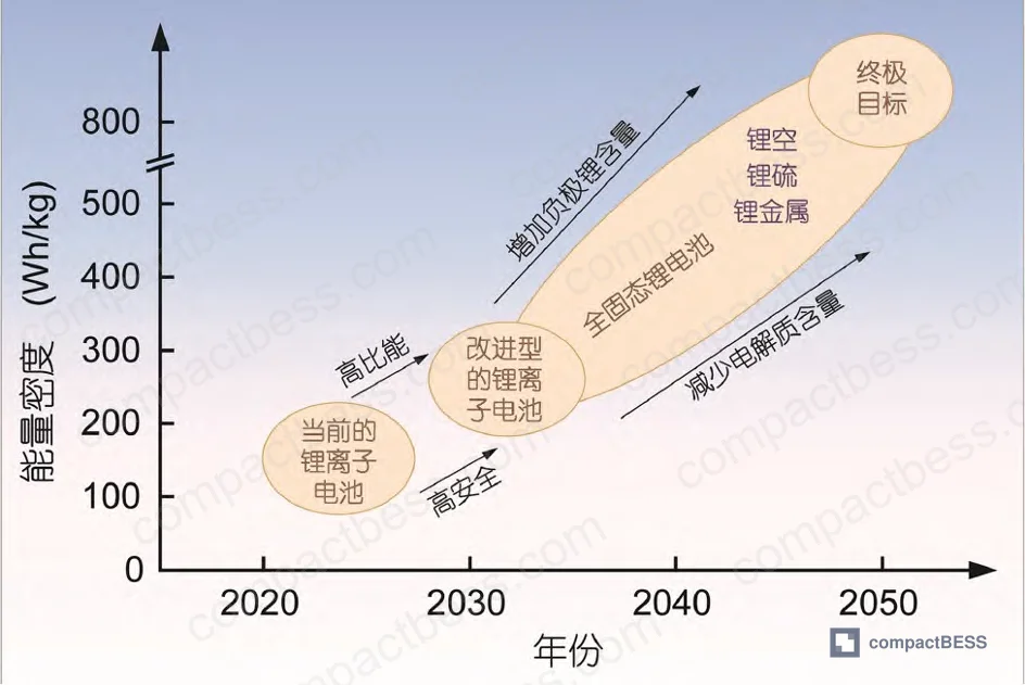
Field evaluations and current industry data point to meaningful commercialization being several years away for most application segments. The barriers are real: interface resistance between solid electrolyte and electrode materials is not fully solved, production costs remain high relative to liquid systems, and manufacturing processes require comprehensive retooling. For internal planning purposes, treat liquid-electrolyte LFP and NMC as the dominant procurement options for this cycle, and use semi-solid or hybrid cells — where they are genuinely available from qualified suppliers — as the bridge technology if your application specifically requires reduced flammability risk.
For deeper guidance on related topics, see our resources on lithium cell chemistry selection and cell cycle life and degradation mechanisms.
Published by compactbess.com Technical Team | Request a sourcing quote


