

TL;DR #
In a validated three-pack parallel BESS configuration with built-in DCDC converters, idle-state standby loss reaches 210 W across the system — equivalent to consuming 2.52 kWh over a single 12-hour overnight period, or 16.8% of total system energy capacity. Buyers specifying residential or C&I energy storage packs with internal DC-DC stages must account for light-load loss budgets in their RFQ requirements, or risk significant parasitic drain eating into round-trip efficiency guarantees. Require suppliers to demonstrate a low-power intermittent mode with documented light-load thresholds, rotation logic, and bus voltage recovery waveforms before accepting any prototype.
Overview #
Before you finalize a battery pack spec for a residential or commercial energy storage project, standby power loss in multi-pack parallel systems is one of the most underestimated cost items in the BOM conversation. Most procurement teams focus on cycle life and energy density; almost nobody asks the supplier how much the system burns at 2 a.m. when the house is asleep.
The analysis here draws on controlled bench testing of a three-pack parallel BESS architecture — each pack rated at 5 kWh with a 50 V nominal cell stack and an integrated DCDC converter boosting to 400 V DC bus. The test setup used a single PCS (power conversion system) connected to a live grid and backup load network, with instrumented measurements at the bus, pack, and cell-current level. Switching loss contribution was isolated from auxiliary supply loss by selectively disabling PWM signals on individual packs — a methodology that gives clean, reproducible data on the dominant loss mechanism.
The core finding: at light load and no-load conditions, switching losses inside the DCDC topology account for the majority of per-pack power consumption. That single insight drives the entire control strategy described below.
Light-Load Power Loss in Multi-Pack DCDC Battery Systems #
This is where most multi-pack BESS designs have a fundamental inefficiency baked in from day one.
Each pack in a normal operating state draws approximately 70 W just to keep its internal DCDC converter running. In a three-pack system, that adds up to 210 W of continuous loss regardless of whether any load is present. Run that overnight for 12 hours and you’ve consumed 2.52 kWh — 16.8% of the total 15 kWh system capacity — doing nothing except staying ready.
The loss breakdown matters for supplier conversations. It’s not the auxiliary power supply causing this; those are relatively low and fairly constant. The dominant contributor is switching loss in the main DCDC topology. When you shut down the PWM switching in a pack — essentially stopping the converter from “firing” — the standby loss per pack drops to approximately 4.6 W. Two packs in true standby therefore consume only 9.2 W combined, versus the 140 W they’d burn in full active mode. That’s a 128.8 W saving just from putting two of the three packs to sleep.
The intermittent working mode solution builds on this insight directly. Instead of running all three packs continuously, the system designates one pack as the “intermittent pack” — the single active converter maintaining bus voltage — while the remaining packs enter standby. The intermittent pack itself also operates in a pulse mode rather than continuous PWM, further reducing its average switching losses. The net result across the full system is a 66% reduction in light-load loss, verified through actual hardware testing.
| Operating State | Per-Pack Loss | 3-Pack System Loss | 12-Hour Energy Consumed |
|---|---|---|---|
| All packs active (no load) | ~70 W | ~210 W | 2.52 kWh |
| 2 packs standby + 1 active | ~4.6 W (standby) | ~81.2 W est. | ~0.97 kWh |
| Intermittent mode (optimized) | Reduced switching | ~71 W saving | ~0.85 kWh saved |
| Final optimized state | — | ~66% reduction vs. baseline | ~1.66 kWh saved |
Honestly, most buyers over-specify peak discharge performance and completely ignore the light-load efficiency curve. If your application has significant overnight idle periods — residential ESS, backup UPS, off-grid solar — the standby loss architecture is as important as the C-rate spec. A supplier who can’t show you a verified light-load loss figure below 80 W for a 15 kWh three-pack system is not engineering to current field standards.
Intermittent Mode Control Architecture and Bus Voltage Management #
The control logic that makes this work is non-trivial, and it’s worth understanding in detail before you ask suppliers to demonstrate it.
Entry conditions are dual-gated: the system only enters low-power intermittent mode when (1) average cell current across all packs is positive and below 3 A, and (2) this condition has been sustained for a minimum of 10 seconds. At 50 V nominal cell voltage, a 3 A threshold corresponds to 450 W — so anything below 450 W system load triggers the mode transition. This threshold is configurable, but the 10-second dwell time is important: it prevents rapid mode-switching from transient load spikes, which would create its own switching losses and control instability.
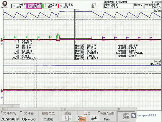
Bus voltage operating window is set at 380 V to 480 V during intermittent operation. This range was determined empirically — maintaining bus voltage within this band keeps the DCDC operating in a favorable efficiency region while providing enough headroom to absorb load transients without triggering protection faults.
Exit conditions are where the design gets interesting, and where poorly engineered systems get into trouble. Four distinct exit triggers are defined:
- Rotation timer expires — the active intermittent pack runs for a maximum of 10 minutes before the system rotates to a different pack. The selection logic prioritizes the pack with the highest SOC for intermittent duty, ensuring energy drawdown is balanced across all packs over time.
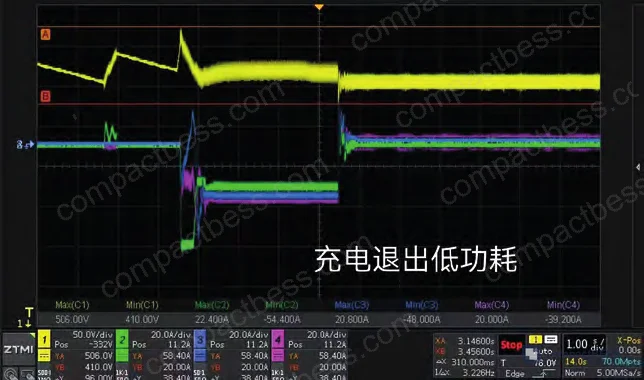
- Charging detected — if charging current exceeds 5 A (equivalent to 250 W at 50 V cell voltage), the system exits intermittent mode and brings all packs back online. For large charging transients, the bus voltage rising above 510 V triggers an immediate broadcast exit command to all packs.
- Load increase detected — if the intermittent pack detects current demand rising above 3 A during its active window, it broadcasts a standby-exit command to all other packs. For sudden large load steps, bus voltage dropping below 420 V triggers the same broadcast — this threshold is deliberately set above the undervoltage protection point to ensure the bus stabilizes before protection faults can occur.
- Manual/system override — any pack can issue or respond to a broadcast exit command.
Most procurement teams don’t realize that bus voltage recovery speed after a standby-exit event is one of the most failure-prone aspects of this architecture. The system must ramp the bus from a potentially depressed voltage back into the 380–480 V operating window fast enough to prevent undervoltage protection tripping, but slow enough to avoid overvoltage faults at the 510 V ceiling. That 90 V of headroom is not generous. Suppliers who have not done waveform-level validation on the exit transient — including a sudden full-load step from zero — should not be on your approved vendor list.
Communication architecture is CAN-based, aligned with relevant charging station communication standards. Each pack broadcasts its address, cell voltage, cell current, SOC, and current intermittent-pack address on a timed schedule. Every pack maintains a local system table with this data for all packs — so any pack can make autonomous decisions without depending on a central controller. The pack with the lowest CAN address is designated as master and is responsible for selecting the highest-SOC pack for intermittent duty. This distributed architecture is resilient: if the master pack fails, address-based selection logic can re-establish coordination.
Practical Guidance for Buyers #
If you’re procuring multi-pack parallel BESS for residential, light commercial, or off-grid applications, the standby loss budget needs to be on your technical datasheet requirement list — not an afterthought discovered during commissioning.
Require any supplier to provide measured standby loss data at the system level (not just per-pack), tested at no-load and at 10–20% of rated load. The 66% loss reduction achieved in the validated architecture described here sets a reasonable benchmark: a 15 kWh three-pack system should be demonstrably below 80 W total loss in light-load intermittent mode. If a supplier cannot produce oscilloscope waveforms showing entry/exit transients and multi-pack rotation behavior, they are quoting you a paper design.
Also check CAN communication frame compliance. The intermittent mode control depends entirely on reliable broadcast messaging between packs. A supplier using a proprietary protocol that hasn’t been validated against charging station communication standards is a system integration risk.
At CompactBESS, we work with verified manufacturers across Guangzhou and the wider Pearl River Delta who supply parallel BESS pack solutions — including those with integrated DCDC and validated low-power mode firmware — to OEM buyers in North America, Europe, and the Middle East. If you’re at the supplier qualification stage, our team can help you structure technical evaluation criteria and match you with manufacturers who have documented light-load loss data.
Need help identifying qualified suppliers for multi-pack BESS with verified intermittent mode control? Talk to our sourcing team →
Supplier Qualification Questions #
- What is the measured per-pack standby loss (in watts) when PWM switching is disabled, and can you provide test data showing the contribution of switching loss versus auxiliary supply loss separately? Baseline: standby loss per pack should be ≤5 W when switching is halted.
- At what system-level load threshold (in watts or amperes) does your low-power mode activate, and is the 10-second dwell timer before mode entry configurable in firmware? The reference architecture uses a 3 A / 450 W threshold with a 10-second confirmation window.
- What is the measured bus voltage recovery time (in milliseconds) after a sudden full-load step from intermittent mode, and can you provide oscilloscope waveforms showing the voltage dip does not breach the undervoltage protection threshold? The reference system recovers within 10 ms from a zero-to-full-load step.
- What is the rotation interval for intermittent pack duty, and does your SOC-priority selection algorithm guarantee energy drawdown balance across all parallel packs over a 24-hour cycle? The reference architecture uses a 10-minute rotation interval with highest-SOC priority selection.
- What are the bus voltage exit thresholds for both charging and discharge events in your low-power mode, and are these thresholds separated from the hard overvoltage and undervoltage protection points by at least 30 V of margin? Reference values: 510 V charging exit threshold, 420 V discharge exit threshold, with overvoltage protection above 510 V and undervoltage protection below 420 V.
Sourcing Checklist #
- [ ] Supplier can provide measured system-level standby loss data ≤80 W total for a 15 kWh three-pack configuration in intermittent mode
- [ ] Per-pack standby loss with switching disabled is documented at ≤5 W (reference: 4.6 W per pack measured)
- [ ] Light-load entry threshold is configurable and set at ≤450 W (3 A at 50 V) with a minimum 10-second dwell confirmation timer
- [ ] Bus voltage operating window during intermittent mode is maintained within 380–480 V, verified by oscilloscope waveform data
- [ ] Charging exit threshold is ≤510 V bus voltage and/or ≥250 W charging power (5 A at 50 V), with discharge exit threshold ≥420 V — both verified by transient waveforms
- [ ] Multi-pack rotation interval is ≤10 minutes with SOC-priority selection logic confirmed in firmware documentation
- [ ] CAN communication protocol is compliant with IEC 62619 industrial BESS safety communication requirements or relevant charging station standards
- [ ] Overall light-load loss reduction versus no-mode baseline is documented at ≥60% reduction (reference: 66% achieved in validated hardware testing)
Key Specifications Table #
| Parameter | Recommended Value | Verification Method |
|---|---|---|
| System standby loss (3-pack, no load) | ≤80 W in intermittent mode (baseline: 210 W without mode) | Calibrated power meter at DC bus, no-load condition, 30-minute steady-state measurement |
| Light-load entry threshold | ≤450 W / 3 A average cell current | Firmware parameter readout + current clamp verification at pack terminals |
| Bus voltage operating window (intermittent mode) | 380 V – 480 V DC | Oscilloscope measurement at PCS bus terminals during intermittent operation |
| Charging exit threshold (bus voltage) | ≤510 V DC (hard limit above this) | Oscilloscope waveform: simulated charging ramp test, confirm exit before OVP activation |
| Discharge exit threshold (bus voltage) | ≥420 V DC (above UVP point) | Oscilloscope waveform: full-load step test, confirm 420 V floor not breached before recovery |
| Intermittent pack rotation interval | ≤10 minutes | System log or CAN bus trace showing rotation timestamps |
| Per-pack switching-off standby loss | ≤5 W | Isolated pack test with PWM disabled, precision power meter |
| Light-load loss reduction vs. baseline | ≥60% (reference: 66%) | Comparative measurement: baseline 210 W vs. optimized mode, same load conditions |
Can’t find a supplier meeting these specs? Submit your requirements and we’ll match you within 48 hours.
Frequently Asked Questions #
Why does a battery pack with no load still consume 70 watts?
The dominant cause is switching loss in the internal DCDC converter topology. Even with zero power delivered to the load, the converter’s MOSFETs or IGBTs are switching continuously at operating frequency, generating heat and consuming power with every switching event. This is distinct from the auxiliary power supply loss, which is lower and relatively constant. Stopping the PWM signal drops per-pack consumption to approximately 4.6 W.
What happens to bus voltage stability when one pack is doing all the work in intermittent mode?
Bus voltage is maintained within the 380–480 V window by the single active intermittent pack. The 100 V operating window provides sufficient headroom for normal load variations. The critical risk is transient response to sudden large load steps — bench testing showed a bus voltage dip during a zero-to-full-load step that recovers within approximately 10 milliseconds before reaching steady state. The 420 V exit threshold is specifically set to catch large load transients before undervoltage protection activates.
Can this low-power mode be retrofitted to existing multi-pack systems?
It depends entirely on the firmware architecture and whether CAN communication between packs supports broadcast messaging with SOC and intermittent-pack address fields. The control logic itself is implemented in software, but the communication protocol needs to carry the right data fields. Systems with proprietary or closed BMS firmware are generally not retrofittable without supplier involvement.
How does the system prevent one pack from bearing disproportionate cycling stress?
The rotation mechanism handles this. Each intermittent pack runs for a maximum of 10 minutes before handing off duty to the next highest-SOC pack. Over a full day of light-load operation, this distributes cycling stress roughly equally across all packs. The SOC-priority selection also means packs with more energy take the active role first, which is thermally and electrochemically favorable.
Does intermittent mode affect the system’s response to sudden grid or load events?
Yes, and this is the key tradeoff. In intermittent mode, only one pack is actively connected and switching. When a sudden load increase or grid charging event occurs, there is a brief window — on the order of milliseconds — while standby packs receive the broadcast exit command and re-engage. The 10 ms recovery waveform from load-step testing shows this is manageable, but systems requiring sub-millisecond response (such as frequency regulation ancillary services) should not rely on intermittent mode during high-availability windows.
For deeper context on how BMS communication protocols support multi-pack coordination, see our guide on BMS communication protocols and our coverage of series-parallel configuration for multi-pack BESS design.
Relevant standards for this application area include IEC 62619:2022 (Safety requirements for secondary lithium cells and batteries for use in industrial applications), UN 38.3 (Transport certification for lithium batteries), and UL 9540 (Standard for Energy Storage Systems and Equipment).
Published by compactbess.com Technical Team | Request a sourcing quote
Data source: Low-Power Intermittent Control Methods for Reducing Standby Losses in Parallel Multi-Pack Battery Energy Storage Systems, L. Liu et al., Journal of the Electrochemical Society, 2024
Content reviewed by michael.tan | © compactbess.com — All rights reserved. Unauthorized reproduction prohibited.


