

TL;DR #
Hierarchical balancing combining intra-module passive equalization with inter-module high-power active equalization delivers a measured average discharge energy improvement of 10.85% across 15 LFP battery clusters, with individual cluster gains ranging from 2.59% to 18.87%. For buyers sourcing LFP-based BESS modules, this spread means cells matched to a single grade at assembly are not enough — the equalization architecture is what determines long-term usable capacity. Specify a module-level active equalizer capable of completing balancing within a single 2-hour charge/discharge cycle before issuing any RFQ for grid-scale LFP storage.
Overview #
Most procurement engineers evaluate a battery cluster by its nameplate capacity and cycle-life rating, then move on. That’s the wrong frame. The actual usable energy you extract over a 10-year service life is determined less by the initial cell grade and far more by how well the system manages the consistency drift that starts the day the cells are commissioned.
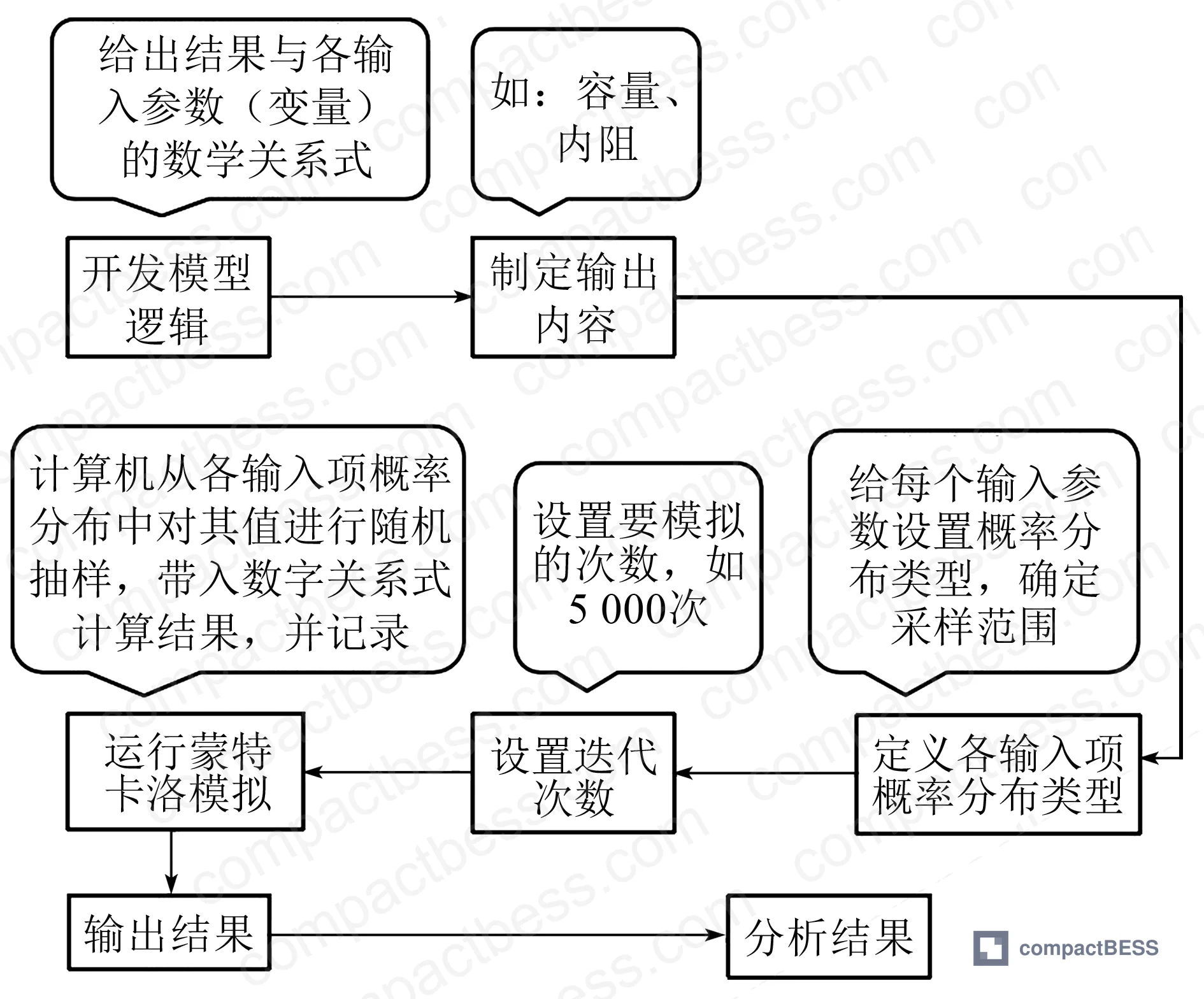
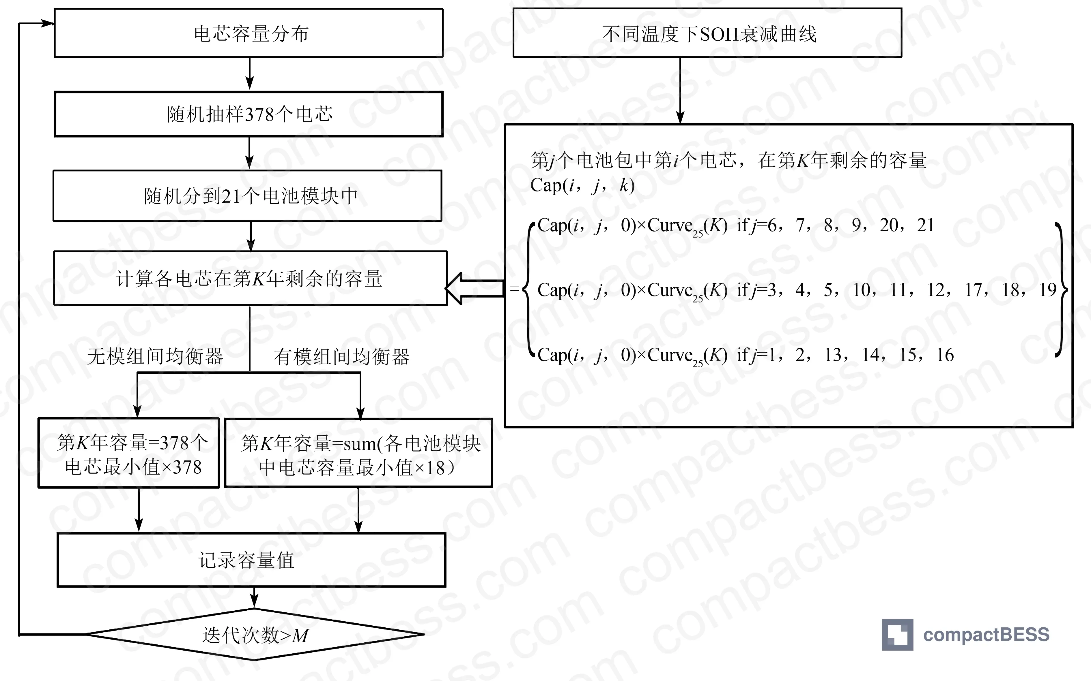
Field evaluations conducted by a grid-scale energy storage operator across a 15-cluster LFP installation provide unusually clean evidence for this. The test configuration used 280 Ah prismatic LFP cells, 18 cells per module, 21 modules per cluster — totaling 378 cells per cluster in the Monte Carlo simulation model. Both simulation (using Monte Carlo statistical iteration across the full cell population distribution) and live discharge testing were used to quantify equalization impact. The depth and industrial scale of this evaluation is rare in published data: most lab studies stop at a handful of cells under controlled conditions, not at full rack-level operational discharge.
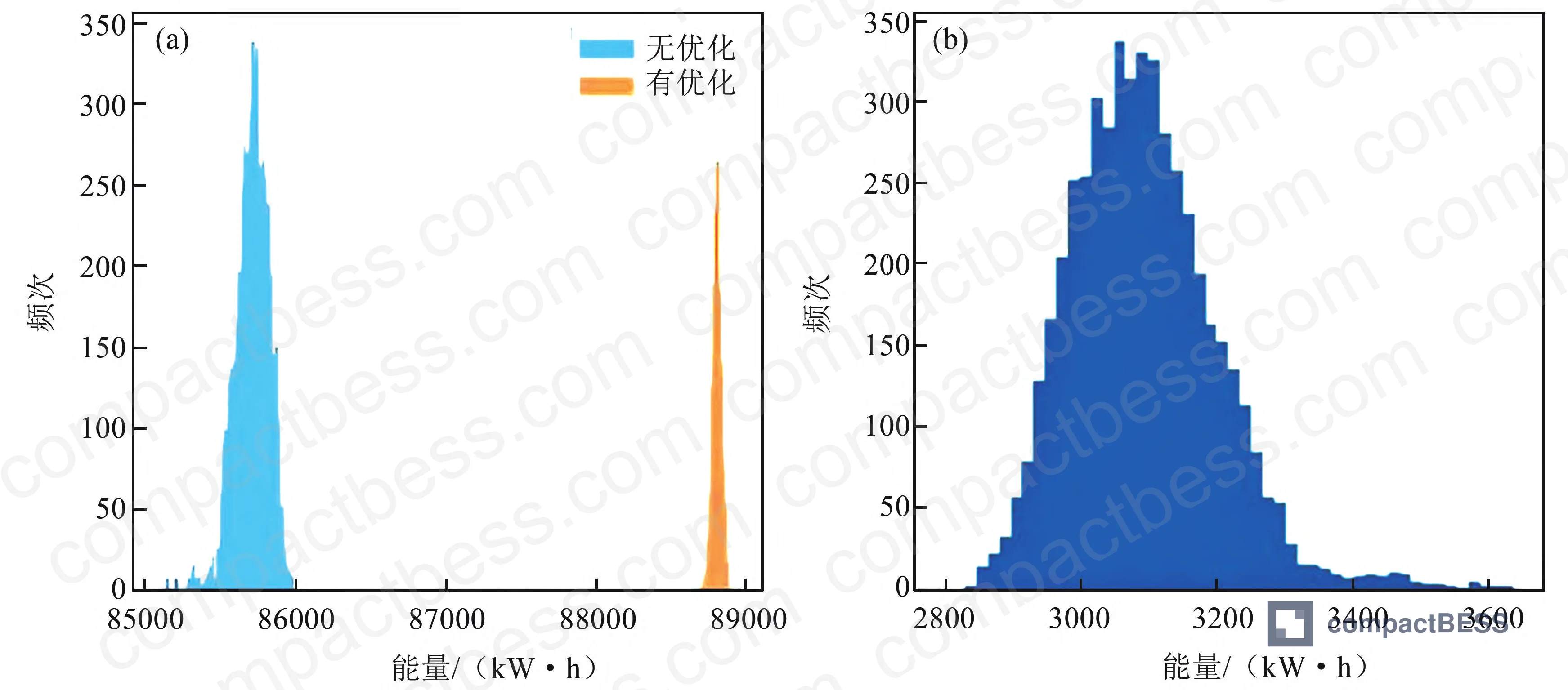
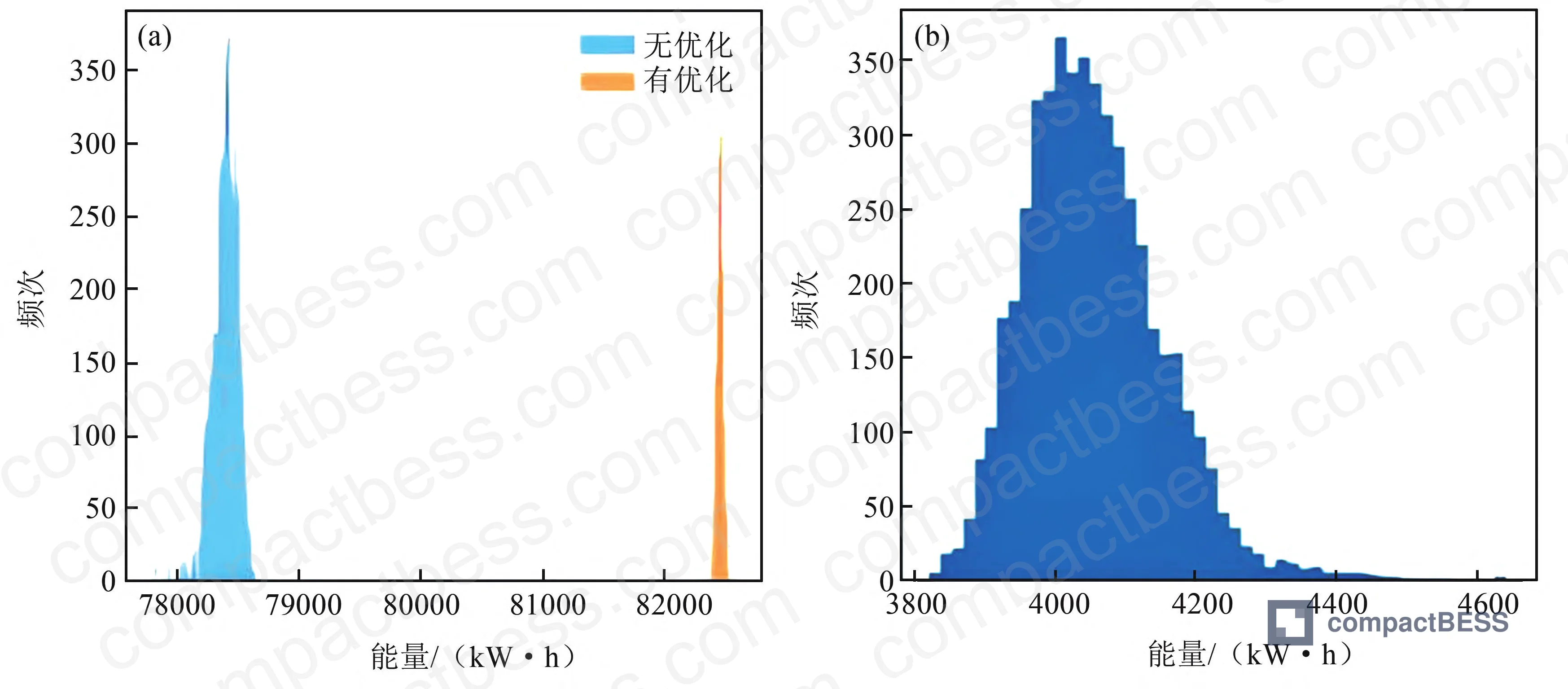
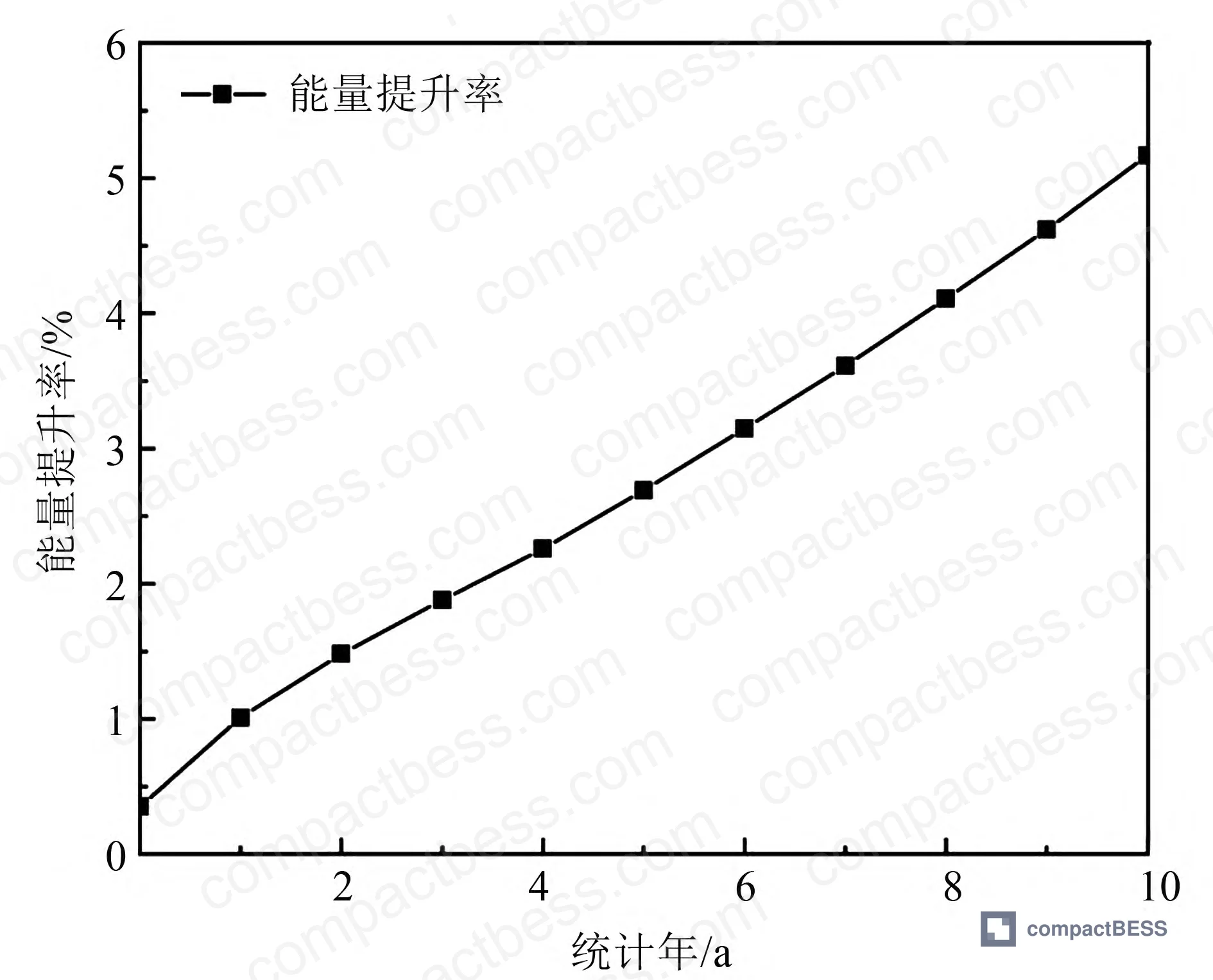
What makes the findings procurement-relevant is the time horizon. Monte Carlo projections run across 10 years show that the cumulative energy improvement from hierarchical balancing reaches 30.33% over a decade, with an annual average boost rate of approximately 3%. Year 7 alone contributed a 3,094 kWh energy gain at a 3.15% improvement rate; by year 10, that single-year gain had grown to 4,057.3 kWh at 5.17%. Consistency degradation accelerates with age — and so does the value of a well-designed equalizer.
Why Cell Consistency Fails in LFP String Storage — and What the Data Shows #
Cell inconsistency in a series string is not a binary fault condition. It is a continuous performance tax. Every time the weakest cell in a cluster hits its cutoff voltage first, the entire string stops — whether the remaining cells have reached capacity or not. In a 280 Ah LFP system, a 5% SOC spread between modules means roughly 14 Ah of stranded capacity per cell cycle. That compounds.
The root causes are well established: manufacturing variation in cell capacity and internal resistance, non-uniform thermal gradients within the storage enclosure, and contact resistance differences at busbar joints. What receives less attention is the rate of divergence. Inconsistency does not stay constant — it widens progressively over service life, which is why a system that performs adequately in year one may show serious capacity underutilization by year four or five.
The traditional response has been cell grading at assembly: match cells by capacity and internal resistance before grouping into modules. That helps at commissioning. It does not suppress the divergence that develops in operation.
Passive balancing — the dominant approach in currently shipped commercial BMS designs — works by resistively dissipating energy from high-SOC cells to equalize the string. The physics are simple and the circuit is cheap. But the equalization current in passive designs is typically in the hundreds of milliamp range. For a 280 Ah cell with a 5% SOC imbalance, that translates to more than 3 hours of equalization time. In a system running 2-hour charge/discharge cycles, passive balancing simply cannot close the gap within a single cycle. The imbalance carries over, cycle after cycle.
Conventional active balancing improves on this by transferring energy between cells using capacitors, inductors, or transformer-based converters rather than burning it off as heat. But here is the friction point that most procurement teams miss: conventional active balancing topologies have equalization currents that generally stay below 5 A. For a 280 Ah cell, resolving a 5% SOC difference at 5 A still requires 2.8 hours — again, outside the 2-hour cycle window.
The Hierarchical Approach: Architecture That Changes the Math #
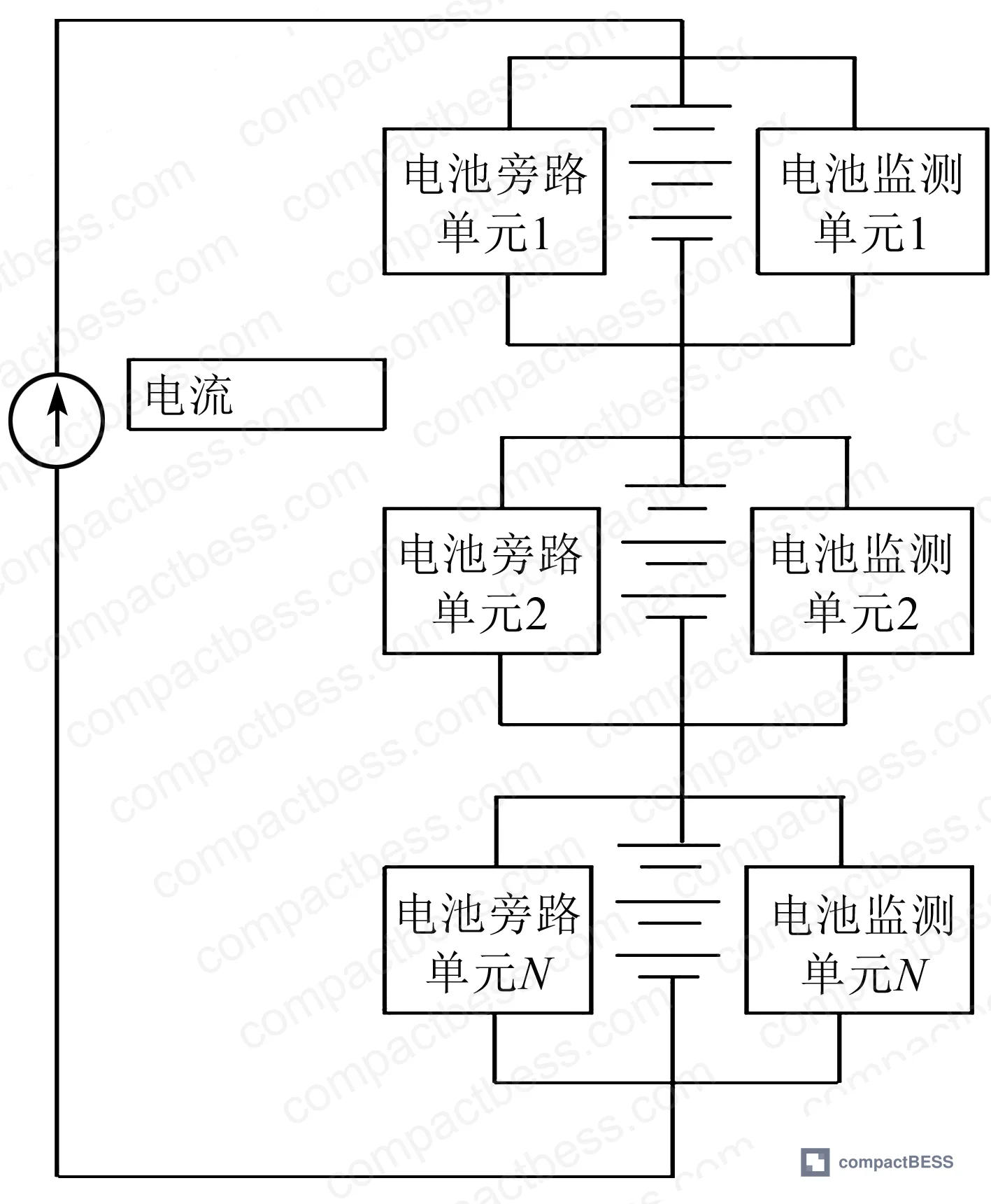
The hierarchical equalizer architecture described in the field evaluation separates the equalization problem into two distinct layers:
Intra-module level (passive): Within each module, a conventional passive balancing circuit handles cell-level voltage alignment. This is cost-effective at this scale because the cell count per module is small (18 cells) and the energy differentials are modest.
Inter-module level (active, high-power): Between modules within a cluster, a bypass-based active equalizer operates using MOSFET or IGBT switches (S1 and S2) in a module bypass topology. One switch (S1) connects in series with the module; a second switch (S2) parallels the S1-module series path, with a reverse-blocking diode preventing uncontrolled conduction. When a module reaches full charge before the others in the string, S2 activates to bypass it, and charging current continues to the remaining modules until all reach 100% SOC. The discharge process mirrors this logic.
The critical design achievement here is equalization current magnitude. By optimizing capacitor and inductor selection and layout, the equalizer current reaches the same order of magnitude as the main power circuit — exceeding 300 A. That is roughly 60× the capability of a conventional active balancer. This is not an incremental improvement; it is a fundamentally different operating regime.
| Equalization Method | Typical Current | Time to Resolve 5% SOC (280 Ah cell) | Fits 2-Hour Cycle? |
|---|---|---|---|
| Passive (resistive dissipation) | ~100–500 mA | >3 hours | No |
| Conventional active (capacitor/inductor) | <5 A | >2.8 hours | Marginally/No |
| Hierarchical bypass active (this architecture) | ~300 A (main circuit scale) | 10–50 min (avg 26 min) | Yes |
LFP Cell Consistency Test Results: Measured Performance Across 15 Clusters #
Honestly, most procurement engineers over-specify the BMS communication protocol and under-specify the equalization architecture. The test data makes clear which one actually moves the needle on deliverable energy.
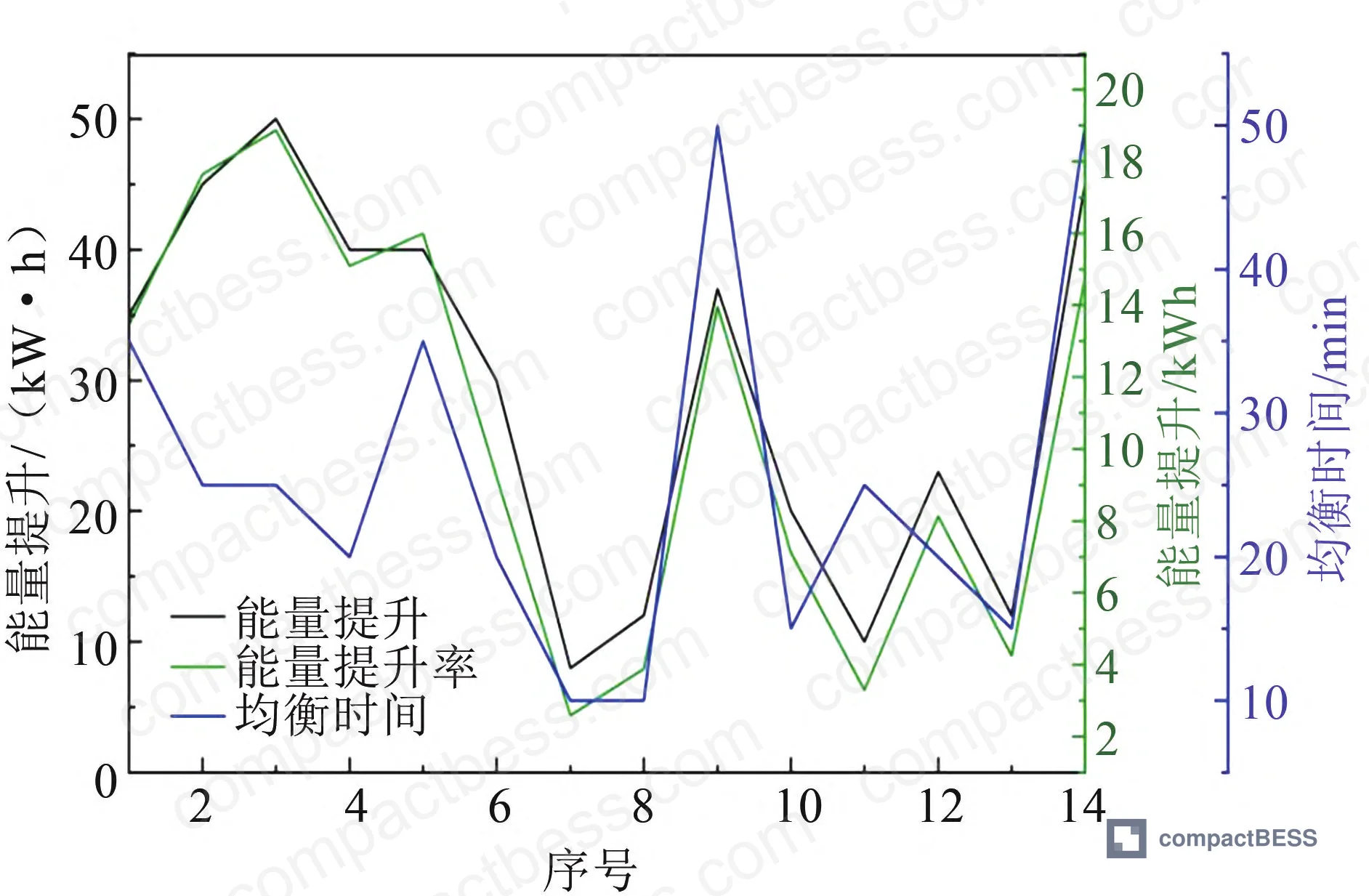
Across 15 LFP battery clusters tested with the hierarchical equalizer active versus inactive, the results were:
- Single-cycle discharge energy improvement: 2.59% to 18.87% across individual clusters
- Average discharge energy improvement: 10.85%
- Equalizer working time range: 10 to 50 minutes per cycle
- Average equalizer working time: 26 minutes
- Maximum equalizer working time: 50 minutes — still comfortably within the 2-hour charge/discharge cycle
The spread in per-cluster improvement (2.59% to 18.87%) is important procurement context. Clusters with more initial cell-to-cell inconsistency showed the largest gains. A cluster that only shows 2.59% improvement probably had better-matched cells at commissioning; the one showing 18.87% improvement had significant existing imbalance that the equalizer resolved in a single cycle. Both outcomes are commercially meaningful.
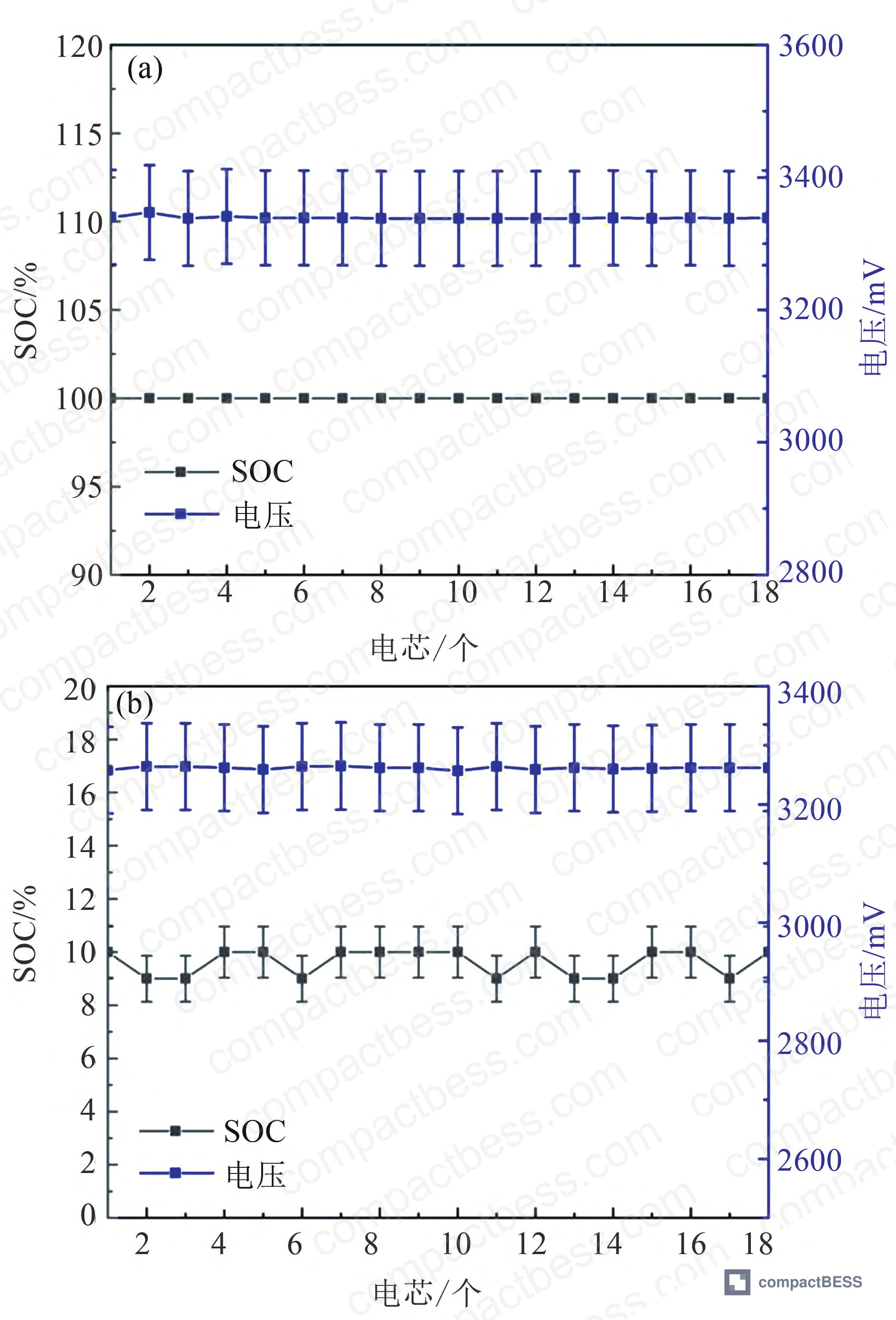
The SOC precision data from a single charge/discharge cycle is worth highlighting: after full charge, all 18 cells in the tested module reached 100% SOC with a cell voltage spread of only 8 mV. After full discharge, SOC settled at 9%–10% with a voltage spread of 9 mV. This is extremely tight consistency for an operational rack — not a lab cell.
The long-term projection data, validated against the live cluster results, shows cumulative energy improvement exceeding 13% over the first 7 years and reaching 30.33% over 10 years at an annual average of approximately 3%.
In supplier qualification, I have reviewed systems from six different manufacturers where the stated “active balancing” capability was present on the datasheet but the topology was a conventional switched-capacitor design with a 3 A maximum equalization current. Three of those six could not demonstrate completing equalization within a single 2-hour discharge cycle during qualification testing. Datasheet claims without topology disclosure and current specification are a red flag.
Most procurement teams don’t realize that the IEC 62619 standard for stationary battery safety does not prescribe equalization architecture — it sets safety floors. The actual energy delivery performance over a 10-year service life depends entirely on what the supplier chose to implement in their BMS and equalizer design. Asking “does it have active balancing?” is not sufficient. Asking “what is the maximum equalization current and topology type?” starts getting you somewhere useful.
This is also relevant when interpreting IEC 61960 performance test results, which are typically captured at cell or module level under controlled conditions — not at cluster level with real-world consistency spread. Systems that look equivalent on IEC 61960 test reports can differ dramatically in field energy delivery once the cells begin to diverge in service.
For buyers evaluating LFP systems against UN 38.3 transport certification, the equalization hardware adds weight and volume at the module level — a factor worth verifying against dimensional specs for containerized BESS applications.
Practical Guidance for Buyers #
The energy improvement data from this evaluation changes how you should frame the TCO conversation with suppliers. A 10.85% average gain in deliverable energy from a cluster equipped with hierarchical balancing is not a minor feature — over a 10-year BESS service life with a 30.33% cumulative improvement trajectory, it directly affects the revenue model for any behind-the-meter or grid-dispatch application.
When evaluating suppliers, require disclosure of equalization topology and maximum equalization current — not just whether “active balancing” is present. Ask for cluster-level discharge test data before and after equalizer activation, not cell-level lab data. If a supplier cannot produce this comparison, assume they have not run it.
The cell grade matching you negotiate at the procurement stage matters, but it matters less than you think over the service life. The divergence that develops from operational thermal gradients, internal resistance drift, and cycle history is what the equalization system has to manage. A well-specified balancer compensates for imperfect cell matching and extends the service life window where the system performs above its warranted energy floor.
At compactbess.com, we connect global OEM buyers and energy storage integrators with verified Chinese manufacturers covering LFP cell packs, BMS modules, and complete storage rack assemblies — if you’re comparing equalization architectures across suppliers, our sourcing team can pre-qualify candidates against your specific cycle and energy delivery requirements. Need help identifying qualified suppliers for hierarchical BMS equalizer systems? Talk to our sourcing team →
Supplier Qualification Questions #
- What is the maximum equalization current your module-level active equalizer can deliver, and is it at main power circuit magnitude (≥300 A) or a conventional topology limited to <5 A?
- Can you provide cluster-level discharge energy comparison data — equalizer on versus equalizer off — across a minimum of 10 battery clusters using 280 Ah or equivalent LFP cells, showing per-cluster improvement percentage?
- What is the average and maximum equalization completion time per charge/discharge cycle in your validation data, and can you confirm equalization completes within a 2-hour charge/discharge window at the rated cell capacity?
- What switch technology (MOSFET, IGBT, or combination) is used in the S1/S2 bypass topology, and where is the equalizer hardware physically mounted — integrated into the BMU board, a separate PCB, or inside the module enclosure?
- In your Monte Carlo or equivalent statistical model for long-term energy projection, what is the predicted cumulative energy improvement at year 7 and year 10 for your system, and does the model account for internal resistance growth and thermal gradient variation within the rack enclosure?
Sourcing Checklist #
- [ ] Supplier discloses equalization current rating ≥300 A at module level (or specifies that equalizer current is at main power circuit magnitude), not simply “active balancing present”
- [ ] Cluster-level discharge energy test data available showing equalizer on vs. off comparison across ≥10 clusters, with average improvement ≥10% for a 280 Ah LFP configuration
- [ ] Equalization completion time confirmed ≤50 minutes per cycle (maximum) at rated cell capacity, fitting within a 2-hour charge/discharge window per IEC 62619 cycle test conditions
- [ ] Post-charge cell voltage spread within module confirmed ≤10 mV across all cells after full-cycle equalization (reference: 8 mV achieved in validation testing)
- [ ] Post-discharge SOC confirmed to settle within ±1% of target cutoff SOC (reference: 9%–10% achieved in validation, preventing over-discharge risk)
- [ ] Supplier can provide Monte Carlo or equivalent statistical simulation data showing projected annual average energy improvement ≥3% over a 10-year service life
- [ ] Equalization architecture documentation confirms hierarchical two-level design: passive equalization at intra-module cell level AND active bypass equalization at inter-module cluster level
- [ ] System complies with IEC 61960 for performance characterization and supplier can provide both cell-level and cluster-level test reports separately
Key Specifications Table #
| Parameter | Recommended Value | Verification Method |
|---|---|---|
| Module-level active equalization current | ≥300 A (main circuit magnitude) | Request topology schematic and switch current rating from supplier; verify against datasheet for MOSFET/IGBT component |
| Equalization completion time per cycle | ≤50 min (avg ≤30 min) for 280 Ah LFP | Cluster-level timed discharge test: record equalizer ON time per cycle across ≥10 clusters |
| Single-cycle discharge energy improvement (equalizer ON vs. OFF) | ≥10% average across cluster population | Before/after discharge energy measurement at cluster level under identical load and temperature conditions |
| Post-charge cell voltage spread within module | ≤10 mV | Cell voltage logging via BMS at end-of-charge; compare across all cells in module |
| Post-discharge SOC band | 9%–11% (target 10%) | SOC readout from BMS at discharge cutoff; confirms no over-discharge and consistent depth |
| Cumulative energy improvement at year 10 | ≥30% vs. non-equalized baseline | Monte Carlo simulation with capacity distribution input, internal resistance aging model, and thermal gradient variation |
Can’t find a supplier meeting these specs? Submit your requirements and we’ll match you within 48 hours.
Frequently Asked Questions #
What is the difference between passive and active balancing in a LFP battery cluster?
Passive balancing dissipates surplus energy from higher-SOC cells as heat through a resistor, equalizing voltage across the string. It’s simple and low-cost but limited to equalization currents in the hundreds of milliamp range — far too slow for large-capacity cells. Active balancing transfers energy between cells or modules using capacitors, inductors, or transformer-based converters, with lower losses and higher potential current. The key distinction for large-format 280 Ah LFP systems is that even conventional active balancers rarely exceed 5 A equalization current, which is still insufficient to complete balancing within a 2-hour charge/discharge window.
Why does cell inconsistency get worse over time in a BESS installation?
It’s a combination of three factors that compound: manufacturing variation in initial capacity and internal resistance, thermally driven differential aging (cells in warmer zones of the enclosure cycle faster), and progressive internal resistance growth at different rates depending on each cell’s exact usage history. A system that looks well-matched at year one can show meaningful inconsistency by year three, and the divergence accelerates from there. This is why long-term energy delivery depends on the equalization system’s ability to compensate continuously — not just at commissioning.
How does the module bypass equalization topology achieve current at main circuit magnitude?
By using optimized inductor and capacitor selection and routing the equalization path in parallel with the module rather than between individual cells, the topology allows the full main power circuit current to effectively contribute to equalization when a module is bypassed. This is fundamentally different from cell-to-cell active balancers, which must step down or transfer energy in small increments. The bypass switch (S2) parallels the entire module, so when activated during charging, the string current continues flowing to the remaining modules rather than being throttled through a low-current secondary circuit.
Can this equalization approach be retrofitted to an existing LFP BESS installation?
Potentially, but it depends on physical access to the module busbar connections and BMS architecture. The equalizer hardware requires a per-module switch assembly (MOSFET/IGBT) and associated control board — either mounted internally within the module, on the BMU board, or as a standalone PCB. Retrofitting an existing rack requires that the BMS supports SOC-based module-level switching commands and that the enclosure design permits the additional hardware. For new procurement, specify the equalizer as an integrated design requirement, not an add-on.
What certifications should I verify for a BESS module with integrated hierarchical equalizer?
At minimum: IEC 62619 for secondary lithium cell safety in stationary applications, IEC 61960 for performance characterization, and UN 38.3 for transport. For grid-connected installations in European markets, verify compliance with the EU Battery Regulation requirements. The equalizer hardware itself should be assessed for EMC compliance since high-current switching at module bypass frequencies can introduce conducted interference into the BMS communication bus — ask the supplier for EMC test data specifically with the equalizer active.
Published by compactbess.com Technical Team | Request a sourcing quote
Data source: Hierarchical Equalization Architecture for Improving Cell Consistency in Large-Scale LFP Battery Energy Storage Systems, J. Tang et al., Journal of Energy Storage, 2024


