

TL;DR #
In a controlled full-scale thermal runaway test inside a 20-foot standard container, CO concentration inside the battery pack reached 194 ppm — triggering the low-alarm threshold — more than 18 minutes before open flame appeared, confirming CO detection as the most reliable early-warning parameter for LFP industrial battery fires. For procurement teams specifying fire detection systems in prefabricated BESS enclosures, this gap is the margin between controlled suppression and catastrophic propagation, and it must be engineered in — not assumed. Specify composite detectors with a CO low-alarm threshold at or below 190 ppm, and validate suppression agent compatibility with the thermal profile of your battery chemistry before approving any system design.
Overview #
Most procurement engineers evaluating prefabricated BESS enclosures focus on cell-level safety ratings and BMS protection logic. That’s understandable — but it leaves a dangerous gap in the fire safety architecture. The more consequential question is: how much warning time does the detection system actually provide, and is the suppression agent matched to the thermal conditions it will face?
Researchers at a national fire safety research institute ran a live thermal runaway experiment using a real LFP battery pack (1000 × 800 × 240 mm) mounted inside a standard 20-foot shipping container configured as a prefabricated storage enclosure. The setup used 17 temperature sensors, 10 composite fire detectors measuring CO, VOC, smoke, and temperature simultaneously, and two 1 kW heating elements to trigger thermal runaway from within the battery module. This is exactly the kind of instrumented, full-enclosure test that most supplier qualification processes never require — but should.
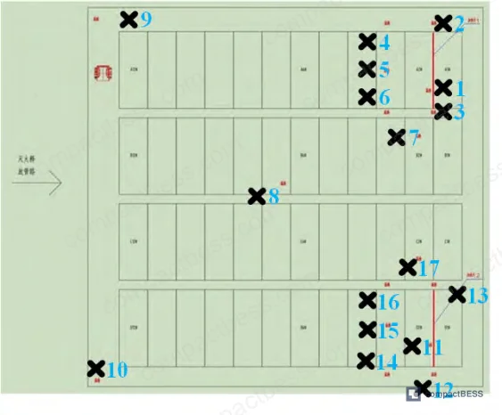
The experiment produced a complete thermal runaway event from initiation through open flame to full suppression using perfluorohexanone (C6F12O), with time-stamped sensor data across all positions. The timeline and gas concentration data from this test form the technical basis for the guidance below.
IEC 62619 Compliance and Thermal Runaway Detection — What the Standard Actually Requires #
IEC 62619 sets the safety requirements for secondary lithium cells and batteries used in industrial applications, including stationary energy storage. It mandates protection against thermal runaway propagation and requires that systems provide warning before hazardous conditions develop. What it does not specify in enough detail — and this is where most buyers get into trouble — is the sensor type, placement strategy, and alarm threshold hierarchy that actually delivers that warning in time.
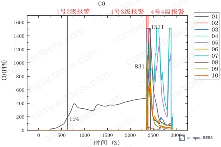
Field evaluations confirm what this experiment demonstrates directly: CO-based detection provides the earliest actionable signal in an LFP thermal runaway event. In the test, the composite detector inside the battery pack recorded a CO concentration of 194 ppm at approximately 11 minutes into the experiment, crossing the low-alarm threshold of 190 ppm and triggering a Level 2 alarm. At this point, the ambient temperature around the detector was only 6°C, VOC was 1.814 V, and smoke had not yet triggered any alarm.

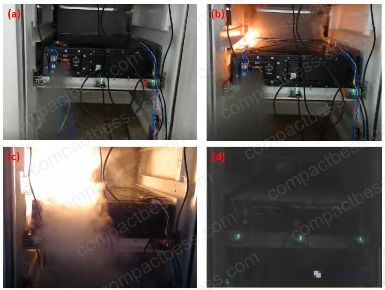
This is critical timing data. The battery pack did not show visible deformation or smoke until 37 minutes 25 seconds into the test — roughly 26 minutes after the CO alarm fired. Open flame appeared at 39 minutes 27 seconds. That means CO detection provided over 18 minutes of pre-flame warning time. No other parameter — temperature, smoke, or VOC — came close to matching that lead time at this stage.
By the time the Level 3 alarm triggered, CO had climbed to 831 ppm (surpassing the high-alarm threshold of 500 ppm), VOC reached 2.469 V, and all parameters were in rapid-rise phase simultaneously. CO eventually peaked at approximately 1,511 ppm — the sensor’s full-scale limit — with VOC at 3.1 V. At that point, the situation is already in the open-flame stage. The 190 ppm threshold is the one that matters for early intervention.
Most procurement teams don’t realize that composite detector specifications for BESS applications vary significantly between suppliers — and that many systems sold as “fire detection compliant” use CO alarm thresholds set at 500 ppm or higher, which in this test profile would have provided essentially zero pre-flame warning. The difference between a 190 ppm low-alarm and a 500 ppm single-threshold detector is the difference between 18 minutes of warning and none.
| Detector Parameter | Early Stage (Level 2 Alarm) | Late Stage (Level 3 Alarm) | Open Flame Stage |
|---|---|---|---|
| CO Concentration | 194 ppm (low alarm) | 831 ppm (high alarm) | ~1,511 ppm (sensor max) |
| VOC Level | 1.814 V | 2.469 V | 3.1 V |
| Ambient Temperature | 6°C | 5°C | Rapid rise |
| Smoke Alarm Status | Not triggered | Triggered simultaneously with CO high alarm | Active |
| Time from Test Start | ~11 min | ~39 min | 39 min 27 sec |
The spatial distribution of CO detection is equally important. In supplier qualification testing with multi-position detector arrays, the detector placed inside the battery pack identified electrolyte leakage at a significantly earlier time than all nine external detectors. The external detectors only registered CO concentration increases after the Level 3 alarm from the internal unit — at which point open flame was already present or imminent. This confirms that exterior-only detector placement, which is the default configuration in many commercial prefabricated enclosures, misses the most valuable detection window entirely.
Perfluorohexanone Suppression Effectiveness in High-Density LFP Battery Enclosures #
The suppression side of this experiment is equally instructive — and the results come with an important caveat that suppliers of gas suppression systems often do not volunteer.
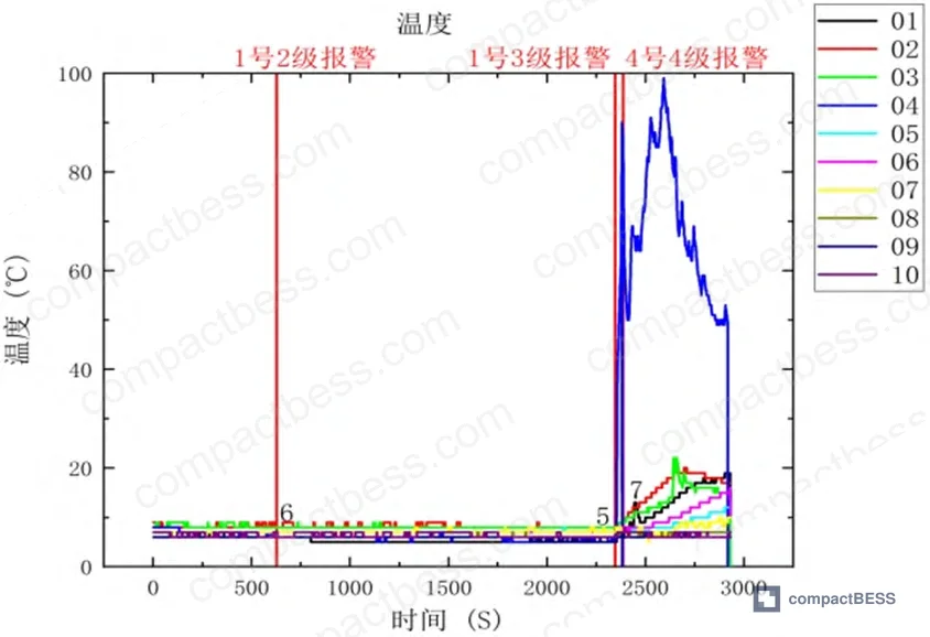
Perfluorohexanone (C6F12O, also referred to as Novec 1230 equivalent or perfluoroketone) was used as the suppression agent, sprayed into the container after the Level 4 temperature alarm was triggered by detector No. 4, which was positioned directly above the ignition point. Detector No. 4 recorded a temperature rise from 25°C at 39 minutes 17 seconds, reaching the 80°C Level 4 alarm threshold at 39 minutes 41 seconds — a rise of 55°C in just 24 seconds.
Following suppression agent deployment, flame visibly reduced. The fire was completely extinguished at 51 minutes 31 seconds. After suppression, smoke gradually dissipated and no re-ignition occurred. These are the outcomes that matter in a prefabricated enclosure scenario.
However, the thermal sensor data tells a more nuanced story about what happened inside the battery pack. At the moment of thermal runaway initiation, the internal temperature sensor nearest the heating element (U1) reached 251°C, then declined after the first heating cycle was stopped. When the second spontaneous propagation phase began, sensors U1, U2, and U11 showed rapid temperature increases, followed within 20 seconds by U4, U5, U7, U12, U15, and U17. Peak internal temperature was reached approximately 62 seconds after U1 began rising in the second phase. Critically, temperature sensors U8, U9, and U10 never exceeded 30°C throughout the entire test, confirming that thermal runaway was confined to the right half of the battery pack.
Honestly, most buyers over-specify suppression system capacity by calculating worst-case whole-pack thermal runaway, when the data consistently shows that early-stage events are spatially confined. The implication is not to under-design suppression — it is to design detection and suppression in sequence, using early CO alarm to trigger agent deployment before the event spreads.
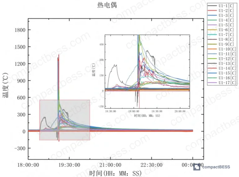
There is a known limitation with perfluorohexanone that the industry does not discuss consistently: the compound begins to decompose above 550°C. In a fully developed, high-density battery fire where local temperatures exceed this threshold, perfluorohexanone’s effectiveness degrades. In this experiment, the suppression was applied at the early-to-mid stage of thermal runaway, before internal temperatures in the broader pack reached that decomposition point — and it worked. Suppliers quoting perfluorohexanone as a drop-in solution for worst-case fully developed BESS fires are overstating its applicability.
Compared to heptafluoropropane (HFC-227ea), perfluorohexanone has lower toxicity and a significantly lower global warming potential, making it a better environmental choice under EU F-Gas Regulation and the broader framework of IEC 62619 industrial safety requirements. For systems that must comply with NFPA 855 installation standards in North American markets, the suppression agent’s compatibility with the enclosure classification and occupancy type must also be confirmed during design review.
Practical Guidance for Buyers #
The most actionable outcome from this test is the 18-minute pre-flame CO detection window. If your current BESS enclosure specification does not require a composite detector with a CO low-alarm threshold at or below 190 ppm, positioned inside or immediately adjacent to the battery pack, you are not capturing that window.
Require composite detectors — not single-parameter units. The data shows that CO, VOC, smoke, and temperature each provide different signals at different stages. A system that only triggers on smoke or temperature will activate after open flame is already present.
For suppression, perfluorohexanone in a sealed or semi-sealed prefabricated enclosure is effective at the early-to-mid stage — but only if the detection system provides early enough warning to deploy the agent before internal temperatures exceed 550°C. That means detection system design and suppression system design must be evaluated together, not as separate line items.
At compactbess.com, we work with global OEM buyers and system integrators sourcing prefabricated BESS enclosures, battery clusters, and suppression-integrated container solutions from verified Chinese manufacturers. If your current supplier cannot provide detector placement specifications or suppression agent thermal compatibility data, that is a qualification gap worth resolving before production begins. Need help identifying qualified suppliers for IEC 62619-compliant prefabricated BESS enclosures? Talk to our sourcing team →
Supplier Qualification Questions #
- What is the CO low-alarm threshold set point on your composite fire detectors, and can you demonstrate it is at or below 190 ppm? Provide the detector model specification sheet showing this threshold.
- What is the placement position of the CO/VOC composite detector relative to the battery pack interior — is any detector positioned inside the battery enclosure, or are all detectors placed externally in the cluster space? Provide the sensor layout drawing.
- At what internal battery temperature does your suppression system initiate agent discharge, and what is the time from Level 4 alarm trigger (80°C threshold) to agent release in your system design?
- What is the rated decomposition temperature of the suppression agent used in your gas suppression system, and how does this compare to the peak temperatures recorded in your own thermal runaway validation tests?
- Can you provide time-stamped thermal runaway test data showing CO concentration, VOC, temperature, and smoke values from at least 3 detector positions at different distances from the ignition source, across the full event timeline from initiation to suppression?
Sourcing Checklist #
- [ ] Composite fire detector CO low-alarm threshold is ≤190 ppm (per experimental alarm Level 2 threshold — not set at the high-alarm value of 500 ppm)
- [ ] At least one composite detector is positioned inside or directly adjacent to the battery pack interior, not exclusively in the external cluster space
- [ ] Detector array covers upper, middle, and lower zones of the battery cluster with minimum 3 vertical monitoring positions
- [ ] Temperature sensors (minimum 15 positions per battery module) provide spatial coverage confirming thermal event confinement or propagation
- [ ] Suppression agent thermal stability is rated above 550°C decomposition point, or agent selection is documented as appropriate for early-stage deployment only
- [ ] Gas suppression system has been tested in a sealed or semi-sealed enclosure equivalent in volume to a 20-foot standard container
- [ ] Suppression test demonstrates complete flame extinction without re-ignition, with post-suppression monitoring confirming no re-combustion event
- [ ] System design complies with IEC 62619 requirements for thermal runaway propagation prevention in industrial stationary storage applications
Key Specifications Table #
| Parameter | Recommended Value | Verification Method |
|---|---|---|
| CO low-alarm threshold | ≤190 ppm | Detector datasheet + factory calibration certificate |
| CO high-alarm threshold | ≤500 ppm | Detector datasheet; verify separate from low-alarm set point |
| Temperature Level 4 alarm threshold | 80°C | System configuration document + test log showing alarm trigger |
| Suppression agent decomposition temperature | >550°C | Agent safety data sheet (SDS) + independent material test report |
| Pre-flame CO warning lead time | ≥18 minutes (vs. open flame) | Full-scale thermal runaway test log with time-stamped sensor data |
| Peak internal battery temperature at runaway | >251°C at initiation point | Internal temperature sensor data from qualification test |
| Post-suppression re-ignition interval monitored | Minimum 30 minutes | Test protocol documentation |
Can’t find a supplier meeting these specs? Submit your requirements and we’ll match you within 48 hours.
References #
Data source: Thermal Runaway Fire Parameter Characterization of Commercial and Industrial Energy Storage Battery Systems in Prefabricated Container Enclosures, Z. Liu et al., Journal of the Electrochemical Society, 2024
Frequently Asked Questions #
Q1: Why does CO detection provide more warning time than smoke or temperature sensors in an LFP thermal runaway event?
CO is generated during early electrolyte decomposition and outgassing, which begins well before the battery casing shows visible deformation or produces smoke visible to optical detectors. In this test, CO crossed the 190 ppm low-alarm threshold approximately 28 minutes before the temperature sensor above the ignition point reached the 80°C Level 4 alarm threshold. Temperature rise at the event location was extremely localized and rapid — 25°C to 80°C in 24 seconds — giving almost no reaction time once it triggered. CO at 190 ppm gives you the lead time to act.
Q2: Is perfluorohexanone (C6F12O) a reliable replacement for heptafluoropropane in all BESS fire scenarios?
Not unconditionally. Perfluorohexanone is effective and environmentally preferable for early-to-mid stage battery fires in enclosed spaces, but it decomposes above 550°C, which limits its effectiveness in fully developed, high-energy fires. Its use is best validated in combination with an early-detection system that deploys the agent before internal temperatures in the broader battery cluster reach critical levels.
Q3: What does IEC 62619 actually require regarding thermal runaway detection and suppression?
IEC 62619 requires that industrial battery systems include protection against thermal runaway propagation and provide hazard warning to occupants or operators. It does not prescribe specific sensor types, alarm thresholds, or suppression agents — those design decisions fall to the system integrator. This is why the detection and suppression specifications outlined above are not automatically satisfied by simply claiming IEC 62619 certification.
Q4: Can the fire detection architecture from this test be applied to other lithium chemistries beyond LFP?
The test used LFP (lithium iron phosphate), which has a comparatively stable thermal profile. NMC and NCA chemistries can reach significantly higher peak temperatures and may produce different gas species ratios. The CO-first detection logic is broadly applicable, but alarm thresholds and suppression agent selection should be re-validated for the specific chemistry in your system.
Q5: Why did only one of the ten cluster detectors show a high-temperature alarm during the test?
Because the suppression system activated quickly after the Level 4 alarm triggered on detector No. 4 — the one positioned directly above the ignition point. The other nine detectors only reached a maximum of approximately 20°C. This is actually a validation of system performance: early agent deployment contained the thermal event before it propagated across the cluster. It is not a sign that the detectors failed; it is evidence that the detection-to-suppression sequence worked as intended.
For deeper context on battery pack safety architecture and protection circuit design relevant to prefabricated BESS enclosures, see our documentation on protection circuit design and IEC 62619 industrial safety.
Published by compactbess.com Technical Team | Request a sourcing quote


