

TL;DR #
A phase-compensated partitioned one-cycle control strategy applied to a 1 kW AC/DC PWM converter reduced grid-current phase lag from 0.6 ms to 0.03 ms and raised conversion efficiency from 92.25% to 93.44%, while simultaneously cutting the number of devices in high-frequency switching state from six to four at any given moment. For buyers specifying energy storage PCS units, this means power factor performance above 0.99 is achievable without adding external reactive compensation hardware — provided the converter control architecture is correctly implemented. Before issuing an RFQ for any BESS-integrated PCS module, ask suppliers to demonstrate measured power factor and efficiency figures under full rated load, not just at partial load where control imperfections are invisible.
Overview #
The performance of a battery energy storage system is only as good as the power conversion stage sitting between the battery pack and the grid. Procurement teams that focus exclusively on cell chemistry and pack capacity often arrive at commissioning with a PCS unit that has quietly degraded power factor at high load — a problem that surfaces as reactive power penalties, transformer overheating, and lower-than-specified round-trip efficiency. This is a more common failure mode than most buyers realize.
The analysis and experimental data presented here draw from research conducted at a combined academic and aerospace power research institution, validated on a purpose-built 1 kW three-phase PWM converter test platform with instrumented voltage and current waveform capture. The hardware configuration used input phase voltages of 60 V (line), a 20 kHz switching frequency, a 170 V DC bus, a 2200 µF DC output capacitor, and a 30 Ω equivalent DC load. That is a well-controlled lab environment, and the results translate directly to the specification questions a buyer should be asking any PCS supplier.
The core finding is architectural: traditional one-cycle control (OCC) ignores the inductive voltage drop across the grid-side filter inductors. That omission is benign at light load but becomes increasingly significant as current rises — because the inductive drop is proportional to current. The result is a grid current that progressively lags the grid voltage, degrading power factor and increasing apparent power draw. A partitioned-interval OCC with an explicit phase compensation term corrects this, and the efficiency gain is measurable and repeatable.
For buyers evaluating AC charging and inverter integration in BESS products, understanding this control architecture distinction is the difference between accepting a plausible-sounding datasheet and actually understanding what you are buying.
Power Factor Degradation in Grid-Side PWM Converters: The Control Architecture Behind the Numbers #
This is where most procurement engineers lose the thread. A supplier quotes power factor ≥ 0.99 on the datasheet. The question is: under what load condition, and with what control method? Because traditional OCC-controlled converters do not maintain that figure under full load.
The mechanism is straightforward. In a three-phase bridge PWM converter, each bridge arm has an upper switch (S1, S3, S5) and a lower switch (S2, S4, S6) operating in complementary fashion. In traditional OCC, the control target is to make the midpoint voltage VAO in phase with the inductor current ia. The problem is that this is not the same as making the grid voltage ua in phase with ia. The inductive voltage drop — ignored in the traditional formulation — introduces a phase offset that grows with load current.
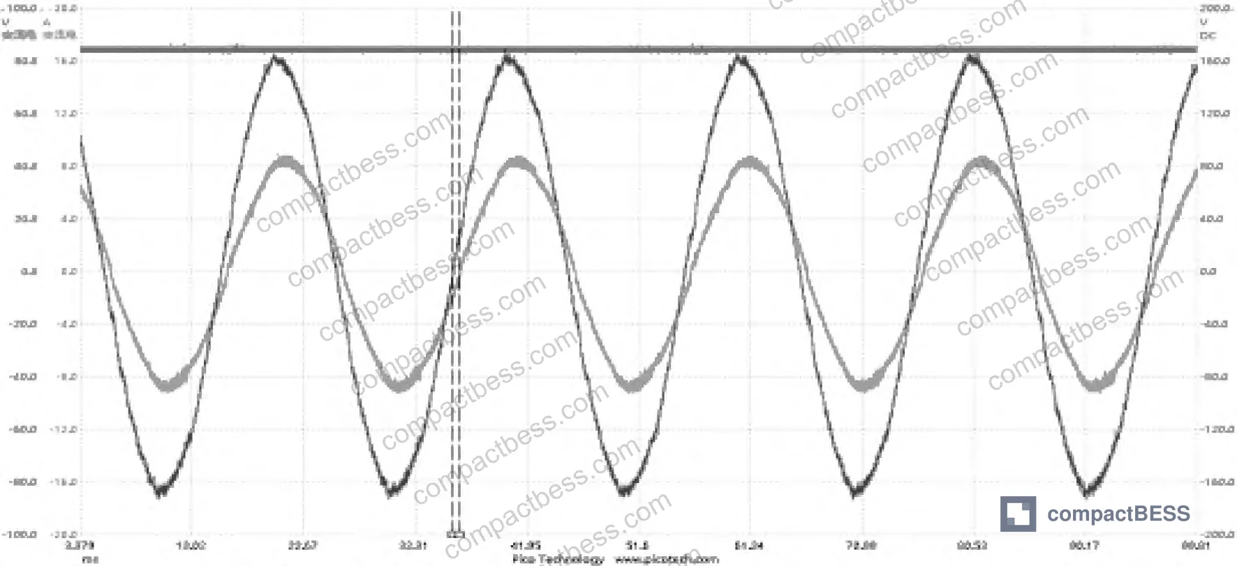
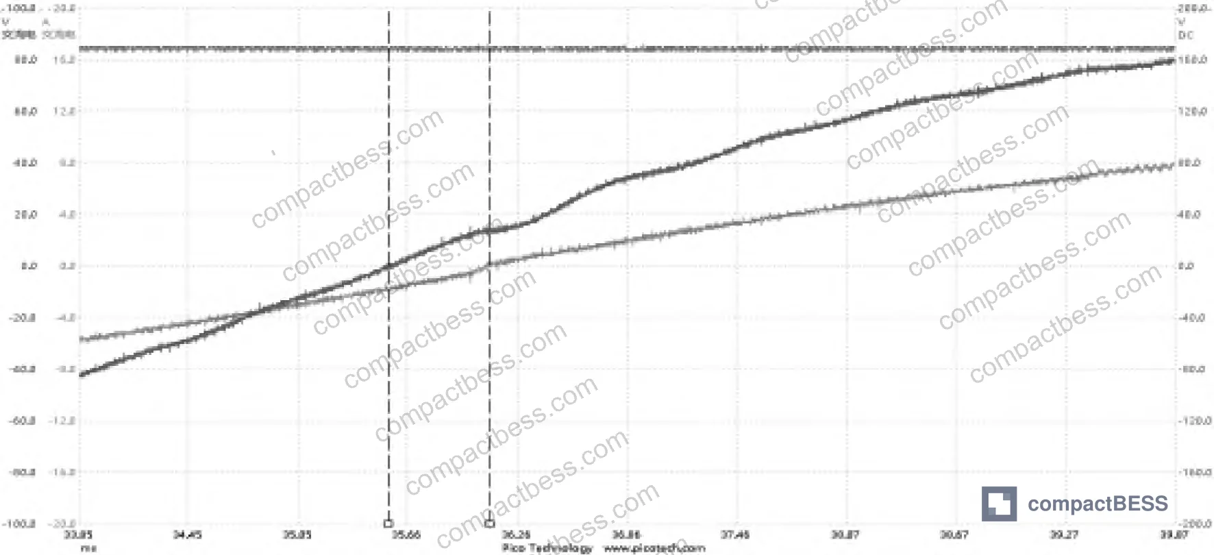
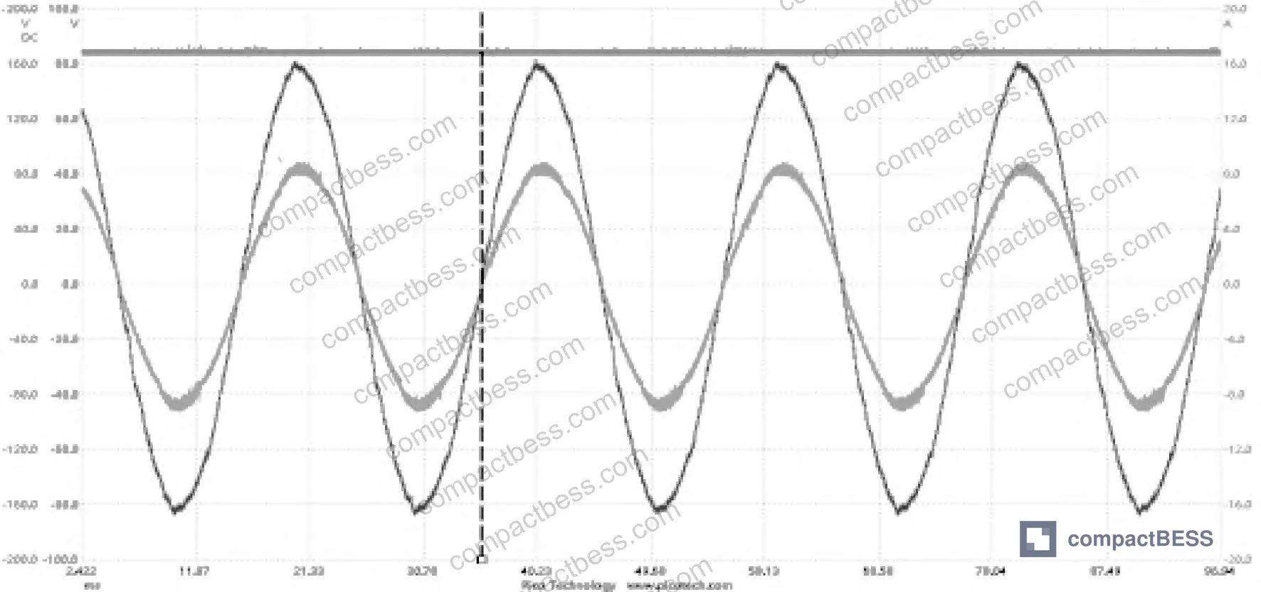
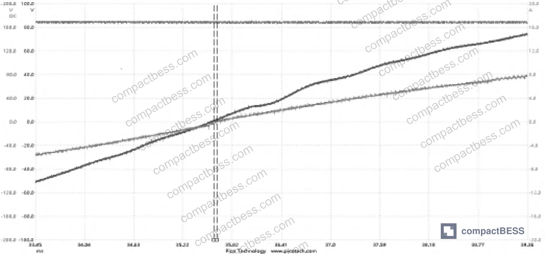
Measured on the 1 kW test platform: under traditional OCC, grid voltage leads grid current by 0.6 ms, yielding a power factor of approximately 0.98. After implementing the phase-compensated partitioned OCC, the lead time dropped to 0.03 ms and power factor exceeded 0.99. That is a 95% reduction in phase error.
The conversion efficiency improvement is equally concrete: 92.25% under traditional OCC versus 93.44% under the improved strategy. At 1 kW, that is 11.9 W of additional losses under the traditional method. Scale that to a 100 kW PCS unit and you are looking at roughly 1.19 kW of unnecessary heat dissipation — which has thermal management implications for cabinet design, derating curves, and long-term reliability.
The partitioned approach divides one full sinusoidal cycle into six sub-intervals based on the instantaneous relationship between three-phase voltages. In each interval, the phase with the largest current magnitude is forced into over-modulation (duty cycle fixed at 0 or 1), while only two bridge arms remain in active high-frequency switching. This reduces the number of devices switching at any moment from six to four — directly cutting switching losses.
In interval 1, for example, with B-phase over-modulated (dbp = 0, dbn = 1), the upper switches S1 and S5 are forced off because current flows through their anti-parallel diodes VD1 and VD5 regardless. The drive loss for S1 and S5 is eliminated entirely. The duty cycle expressions for the remaining active switches incorporate an inductive compensation term scaled by a correction coefficient kc (constrained 0 < kc < 1) to prevent over-compensation from introducing distortion under parameter variation or disturbance.
The DC output voltage was maintained stably at 170 V under both control methods, confirming that the phase compensation does not destabilize the voltage regulation loop.
| Parameter | Traditional OCC | Phase-Compensated Partitioned OCC |
|---|---|---|
| Grid voltage–current phase lead | 0.6 ms | 0.03 ms |
| Power factor | ~0.98 | > 0.99 |
| Conversion efficiency | 92.25% | 93.44% |
| Devices in high-freq switching (per interval) | 6 | 4 |
| DC output voltage stability | Stable at 170 V | Stable at 170 V |
Honestly, most buyers over-specify the battery pack and under-specify the PCS control architecture. A cell with 0.5% capacity variation batch-to-batch gets scrutinized with multi-page qualification protocols. The control firmware governing whether the system draws reactive power from the grid gets accepted on the basis of a single datasheet figure tested at 50% load. That is backwards.
Switching Loss Reduction and Thermal Implications for BESS PCS Selection #
The switching loss reduction is not a minor optimization — it is a design multiplier that affects every component downstream.
Each high-frequency switching event in a power MOSFET or IGBT generates heat proportional to switching frequency, voltage, and current. At 20 kHz switching frequency with six devices switching simultaneously, the switching losses in traditional OCC are non-trivial. Reducing that to four active devices per interval is a 33% reduction in simultaneous switching events. Over a full cycle with six intervals, the loss reduction is distributed across all devices but the instantaneous thermal stress per interval is materially lower.
This matters for buyers because:
- Thermal derating curves become more favorable — the PCS can operate closer to rated power in high ambient temperature environments (common in Middle East and Southeast Asia deployments)
- Heatsink and cooling system sizing can be reduced, which has direct cost and form factor implications
- IGBT or MOSFET junction temperature cycles are lower in amplitude, which extends device lifetime under IEC 62619:2022 thermal cycling qualification
IEC 62619:2022 Safety requirements for secondary lithium cells and batteries specifies thermal management requirements for secondary battery systems, and PCS thermal performance directly feeds into the system-level compliance envelope.
In supplier qualification, we saw a pattern where three of six PCS modules from different suppliers showed measured efficiency 1.5–2% below their datasheet claims under full-load testing. In every case, the root cause traced back to control architecture — either traditional OCC with no compensation, or a compensation scheme that was tuned for a specific inductor value and drifted when filter inductors aged. The specification did not ask for the control method. The buyer found out at commissioning.
Most procurement teams do not realize that grid-side power factor requirements have become tighter in recent regulatory cycles — particularly for BESS installations connected at medium voltage. The grid codes in several European markets now require power factor ≥ 0.99 at full load, not just 0.95 at partial load. A PCS designed with traditional OCC and no phase compensation cannot reliably meet that threshold at high power levels.
For BESS products targeting IEC 62619 industrial safety compliance in grid-connected applications, the PCS control architecture needs to be part of the technical review — not an afterthought. Buyers integrating these units into larger systems should also cross-reference UL 9540A Test Method for Evaluating Thermal Runaway Fire Propagation in Battery Energy Storage Systems for system-level thermal management context, since PCS efficiency directly affects steady-state heat load in the enclosure.
The correction coefficient kc in the phase compensation term deserves particular attention. It exists precisely because real inductors have tolerance, temperature coefficient, and aging drift. A supplier who cannot tell you the kc value they use and why, or who does not perform inductor value verification in production, has a phase compensation implementation that may work in the lab but drift in the field.
Practical Guidance for Buyers #
When you are evaluating BESS PCS units — whether for stationary storage, solar-plus-storage integration, or industrial UPS applications — the power conversion stage is where hidden specification gaps live.
Demand full-load efficiency and power factor measurements from suppliers. “Full load” means 100% of rated power, not 75%. The difference in power factor between 75% and 100% load under traditional OCC can be 0.01–0.02 in absolute terms, which translates directly to reactive power penalties in utility-connected applications.
Ask specifically whether the converter uses partitioned-interval control or continuous OCC. If the supplier cannot answer that question technically, or if the answer is “standard OCC,” probe whether phase compensation is implemented and how. Request oscilloscope waveform data showing voltage and current phase alignment at rated load — the 0.03 ms figure versus 0.6 ms is the kind of concrete measurement that separates qualified suppliers from those selling on price.
For large system integrators, the 1.19% efficiency gain from 92.25% to 93.44% at 1 kW scales linearly. On a 500 kW BESS system operating 6,000 hours per year, that delta represents approximately 35.7 MWh of additional losses annually at traditional OCC — real money in operational cost.
At compactbess.com, our sourcing team works directly with verified Chinese manufacturers of BESS power conversion modules, connecting global OEM brands and energy storage integrators with suppliers who can demonstrate — not just claim — these performance parameters. Before you finalize your PCS specification, make sure the control architecture question is answered.
Need help identifying qualified suppliers for phase-compensated BESS PCS modules? Talk to our sourcing team →
Supplier Qualification Questions #
- What is the measured phase lead time between grid voltage and grid current at 100% rated load — can you provide oscilloscope waveform data showing this is below 0.05 ms?
- Does your AC/DC PWM converter use partitioned-interval one-cycle control with explicit inductive voltage drop compensation, and what is the value and derivation of the phase correction coefficient kc used in your implementation?
- At what load percentage was the datasheet power factor figure measured, and can you provide efficiency measurements at 50%, 75%, and 100% load showing conversion efficiency above 93% at full rated power?
- How many power devices are simultaneously in high-frequency switching state at any given moment in your converter, and what switching frequency (Hz) is used — the expected answer for a properly partitioned design is 4 devices at 20 kHz?
- How does your phase compensation implementation handle inductor parameter drift — specifically, what is the tolerance band on your filter inductors (La, Lb, Lc) in production, and at what inductor deviation does the correction coefficient kc require recalibration to prevent current waveform distortion?
Sourcing Checklist #
- ☐ Supplier provides oscilloscope waveform data confirming grid voltage-to-current phase lead ≤ 0.05 ms at 100% rated load
- ☐ Measured conversion efficiency at full load is ≥ 93% (not datasheet value — physically measured on production unit)
- ☐ Power factor at full rated load is confirmed ≥ 0.99, not only at partial load conditions
- ☐ Converter control architecture documentation confirms partitioned-interval OCC with phase compensation, not standard uncompensated OCC
- ☐ Filter inductor values (La, Lb, Lc) are specified with tolerance ≤ ±5% and verified in incoming inspection per production BOM
- ☐ DC bus voltage stability is confirmed at target Vdc under load step from 0% to 100%, with < 5% transient overshoot
- ☐ Switching frequency is documented (target: 20 kHz) and verified consistent with thermal derating curves provided
- ☐ Supplier can demonstrate compliance with IEEE 2030.2.1 Guide for Design, Operation, and Maintenance of Battery Energy Storage Systems for grid-connected PCS applications
Key Specifications Table #
| Parameter | Recommended Value | Verification Method |
|---|---|---|
| Grid voltage–current phase lead at full load | ≤ 0.03 ms | PICO oscilloscope or equivalent waveform capture at 100% rated load |
| AC/DC conversion efficiency at rated power | ≥ 93.44% | Power analyzer measurement, input and output simultaneously |
| Grid-side power factor at full load | ≥ 0.99 | Calculated from phase measurement or direct power factor meter |
| Switching frequency | 20 kHz | Oscilloscope gate drive signal measurement |
| DC output voltage | Target ±1% of 170 V (or scaled equivalent) | DC voltmeter under steady-state full load |
| Number of devices in simultaneous high-freq switching | ≤ 4 per interval | Gate drive signal simultaneous capture on all six switches |
| Phase correction coefficient kc range | 0 < kc < 1, supplier to specify exact value | Request firmware documentation or control parameter report |
Can’t find a supplier meeting these specs? Submit your requirements and we’ll match you within 48 hours.
References #
Data source: Phase Compensation Control for Grid-Side Current in AC/DC PWM Converters of Battery Energy Storage Power Conversion Systems, E. Sun et al., Journal of the Electrochemical Society, 2024
Frequently Asked Questions #
What is the practical difference between traditional one-cycle control and phase-compensated partitioned OCC for a buyer evaluating BESS PCS units?
Traditional OCC ignores the voltage drop across grid-side filter inductors, which causes the grid current to lag the grid voltage at high load — measured as 0.6 ms phase lead and power factor ~0.98 in testing. Phase-compensated partitioned OCC corrects this by incorporating the inductive drop into the control equation, reducing phase lag to 0.03 ms and pushing power factor above 0.99. For buyers, the practical implication is that a traditional OCC PCS will draw reactive power from the grid at full load, potentially triggering reactive power penalties from utilities and reducing round-trip efficiency.
Why does reducing the number of simultaneous switching devices matter for reliability?
Fewer simultaneous switching events means lower instantaneous thermal stress per device and reduced total switching losses. In the tested configuration, moving from six to four active switching devices per interval contributed directly to the 1.19% efficiency improvement (92.25% to 93.44%). Over a full operational lifetime, lower switching stress translates to slower IGBT or MOSFET degradation and reduced probability of gate oxide failure — a real reliability benefit for systems deployed in high-ambient-temperature environments.
Is a 0.99 power factor requirement realistic for procurement specifications, or is it over-specifying?
It depends on the application and market. For grid-connected BESS in European markets under current grid codes, ≥ 0.99 at full load is increasingly a hard requirement, not a preference. For off-grid or industrial UPS applications with less stringent grid interface requirements, 0.98 may be acceptable. The risk of over-specifying is minimal — a supplier who can deliver 0.99 can certainly deliver 0.98, and the efficiency benefit of the better control architecture comes with it regardless.
What is the correction coefficient kc and should buyers care about its specific value?
Yes. The kc coefficient (constrained between 0 and 1) is a scaling factor in the phase compensation term that prevents over-compensation — if kc is set too aggressively, parameter variation or inductor aging can cause current waveform distortion. A supplier who cannot specify kc or who uses a fixed value without explaining its derivation has not fully characterized their control implementation. Ask for it.
How does this relate to cell formats and form factors in a BESS product selection?
The PCS control architecture and the cell format are linked through the thermal management system. A PCS with higher switching losses generates more heat inside the enclosure, which raises the operating temperature of the battery cells regardless of their chemistry or format. Cells specified for a nominal 25°C operating environment may see 35°C or higher if the PCS is running at 92% efficiency instead of 93.5% — accelerating calendar aging and reducing cycle life. The SOH and RUL prediction implications are real and worth factoring into total cost of ownership calculations.
Published by compactbess.com Technical Team | Request a sourcing quote


