

TL;DR #
If you’re procuring large-format battery energy storage cabinets for grid-scale or commercial deployment, structural integrity during transport is one of the first things that should be on your qualification checklist — and it’s consistently the last thing buyers actually test. A 3,920 kg cabinet riding on a flatbed through 2,000 km of mixed road conditions is not the same problem as shipping a battery module in foam packaging. The dynamic loads are different in scale, frequency content, and consequence.
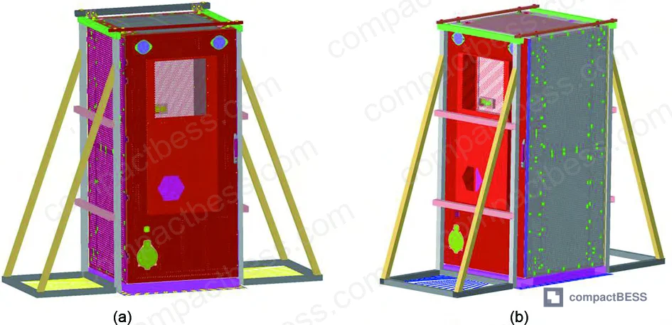
This article draws on shaker-table qualification data from a full-scale BESS cabinet — outer dimensions 1,130 mm × 1,203 mm × 2,521 mm, total mass 3,920 kg — tested under both sinusoidal sweep and ISTA 3E random vibration profiles. We’ll walk through what the test data revealed, where the finite element model held up, where hardware actually failed, and what the numbers mean for your procurement and acceptance criteria.
Sweep Frequency Test Results and Dynamic Characterization #
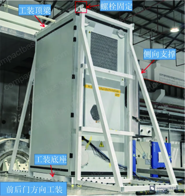
The cabinet was tested on an electrodynamic shaker system (DC-40000-400) with a multi-channel data acquisition controller (Spider-80xi-16). Sweep range was 5–200 Hz in both X and Y directions, at a constant excitation amplitude of 0.1 g, using logarithmic sweep at 1 octave/min. Sampling frequency was set at 3,200 Hz with an analysis bandwidth of 1,250 Hz.
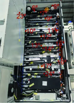
Accelerometers were distributed across 24 measurement points — battery module end plates, cross-beams, beam connectors, smoke/thermal sensors, BMS housing, and front/rear door positions. The shaker table itself carried sensors 1#–4# for closed-loop control.
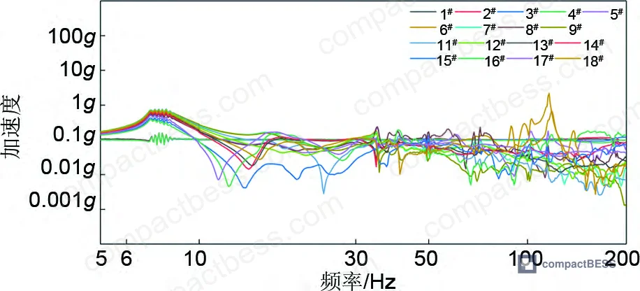
Results from sensor 7# (top cross-beam, front door position) and confirmed by statistical averaging across all measurement points:
| Direction | First-Order Natural Frequency | Damping Ratio (ζ) | Test Method |
|---|---|---|---|
| X (front-rear) | 7.485 Hz | 0.051 | Half-power bandwidth |
| Y (lateral) | 8.431 Hz | 0.070 | Half-power bandwidth |
| Z (vertical) | ISTA 3E random profile | — | 2 h random vibration |
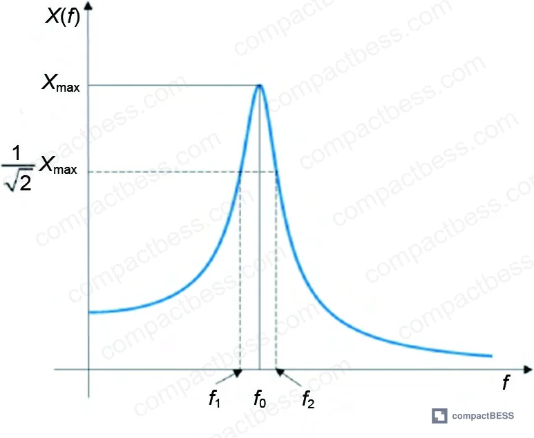
The half-power bandwidth method was used throughout to extract damping ratios. Individual sensor results for the Y-direction ranged from ζ = 0.062 (sensor 17#) to ζ = 0.076 (sensor 7#), and X-direction results ranged from ζ = 0.048 (sensor 17#) to ζ = 0.055 (sensor 7#). The spread is meaningful — it tells you the structure is not behaving as a rigid body, and local compliance at module end plates and beam connectors is contributing to the modal response.
Honestly, most buyers over-specify vibration acceptance criteria by demanding compliance with automotive-grade profiles (SAE J2380 or equivalent) when the application is a stationary cabinet in ground transport. The frequency range and ASD levels in those specs are written for vehicle powertrains — not for a near-4-tonne box on a flatbed. A cabinet like this one, with natural frequencies in the 7–9 Hz range, is going to see resonance excitation from road-surface roughness inputs at highway speed. Specifying a flat 0.1 g sweep up to 200 Hz as your acceptance criterion tells you very little about real transport risk without correlating it to the ISTA profile.
Random Vibration Testing: ISTA 3E Profile and Observed Failures #
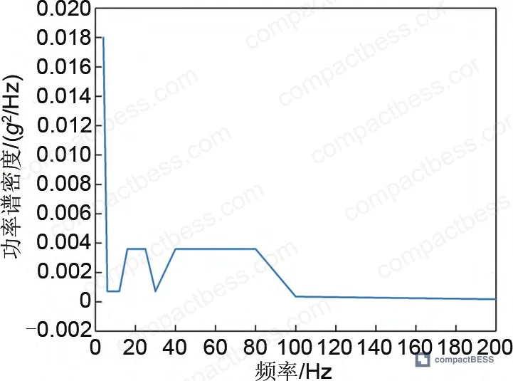
The vertical (Z-direction) random vibration test ran for 2 hours continuous using the ISTA 3E road spectrum — a power spectral density profile specifically developed for consolidated shipments requiring long-haul truck transport. The choice of ISTA 3E is appropriate here: it’s calibrated for large, heavy units transported as a single assembly, which matches the operational profile of a grid BESS cabinet far better than most IEC transport annexes.
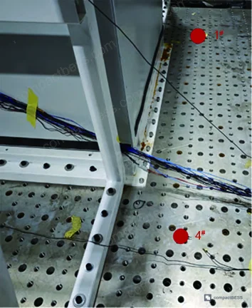
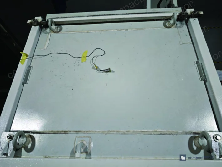
Cabinet body motion during the test was described as low amplitude with minimal impact noise. At the 1-hour mark, the test was stopped for inspection. Post-test visual examination found no apparent structural damage or permanent deformation to the cabinet body.
Then we opened the cabinet.
The mounting bolt at the lower-right cabinet base — connecting the cabinet to the fixture baseplate — had torque-decayed from 50 N·m to 23 N·m. That’s a 54% loss of preload after just 2 hours under ISTA 3E loading. The cross-beam bolts inside the cabinet showed no measurable torque decay. The fixture top cross-beam bolts also showed loosening, consistent with the FEA stress results discussed in the next section.
This is the kind of result that should make any procurement team rethink their incoming inspection criteria. A bolt torque decay of 54% on a 3,920 kg cabinet after a 2-hour lab simulation of truck transport is not a minor anomaly — it’s a structural signal. In supplier qualification, that finding alone would trigger a design review request for thread-locking treatment or positive retention features on all primary structural fasteners before shipment approval.
Most procurement teams don’t realize that ISTA 3E was last substantially revised as part of ISTA’s General Simulation Performance Tests framework, and the vertical PSD profile it uses is based on consolidated LTL freight data that may not fully represent single-pallet or crated heavy machinery shipments in all geographic markets. If your supply chain routes cabinets through port handling and multi-modal transfers, the horizontal excitation content from crane lifts and ship motion is not captured in ISTA 3E at all — and that’s a gap worth closing with supplemental test requirements.
Finite Element Modeling and Simulation Validation #
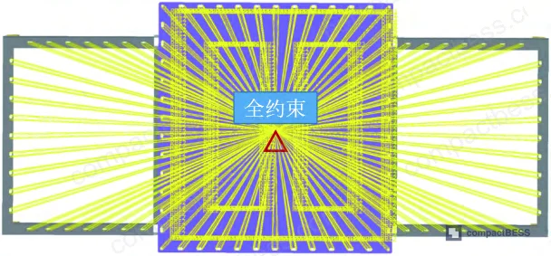
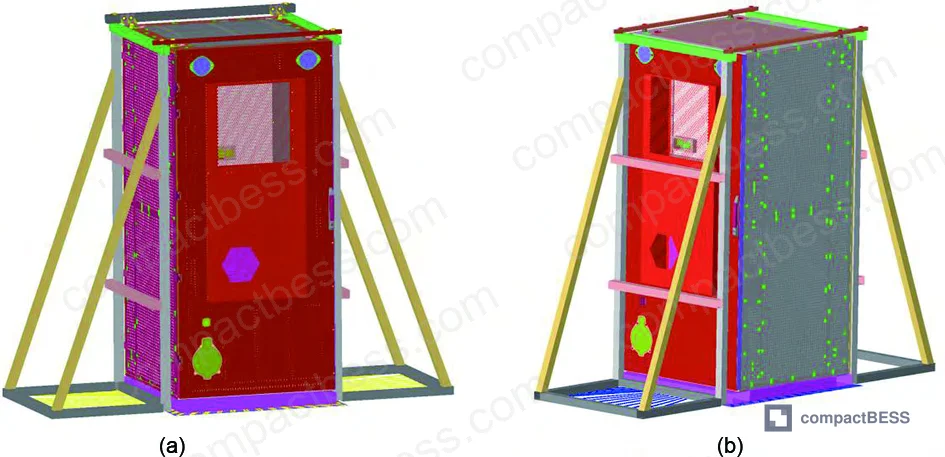
The FEA model was built using HyperMesh for pre-processing and Abaqus as the solver. Total mesh count: 509,785 elements and 418,273 nodes. Structural components were modeled with material properties as follows:
- Cold-rolled carbon steel sheet (SPCC): E = 210,000 MPa, ν = 0.3, ρ = 7.85×10⁻⁹ t/mm³, yield strength 200 MPa
- Q355 structural steel: E = 210,000 MPa, ν = 0.3, ρ = 7.85×10⁻⁹ t/mm³, yield strength 355 MPa
- Aluminum plate: E = 69,000 MPa, ν = 0.3, ρ = 2.77×10⁻⁹ t/mm³
Non-structural components — liquid cooling lines, BMS hardware, smoke and thermal sensors — were excluded from the structural model. Battery cells were modeled as homogeneous solids. These simplifications are standard practice and the resulting frequency error was acceptable, but they do mean the model cannot capture local inertia effects from cooling fluid or electronic assembly mass.
Modal Analysis Results #
Modal analysis used a two-step approach: first a nonlinear static step to capture pre-stress from contact and gravity, then a linear perturbation modal step. Locating pin contact was modeled as normal “hard” contact with tangential penalty friction.
FEA modal results versus measured values:
| Mode Configuration | FEA Frequency (Hz) | Test Frequency (Hz) | Error |
|---|---|---|---|
| X-direction, 2nd mode (1st structural) | 7.727 | 7.485 | +3.23% |
| Y-direction, 2nd mode (1st structural) | 8.746 | 8.431 | +3.74% |
Both errors fall within 5% of measured values — the standard acceptance threshold for FEA model validation in structural dynamics work per IEC 62619 supplementary guidance. That’s a solid validation result for a model of this complexity.
Sweep Vibration Simulation vs. Measured Data #
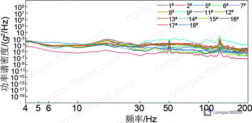
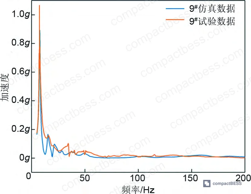
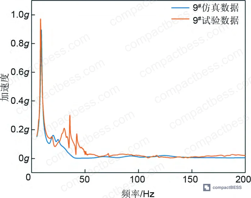
Sweep simulations used measured damping ratios as input and extracted nodal acceleration responses at sensor locations. Sensor 9# was used as the primary validation point. The simulated acceleration-frequency curves for both X and Y directions showed strong agreement with test data in amplitude and frequency characteristics, with discrepancies confined to local frequency bands — consistent with the linear assumption in the model excluding contact and geometric nonlinearity.
Random Vibration Stress Distribution #
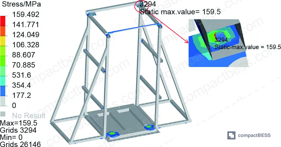
Z-direction random vibration simulation used the ISTA 3E PSD as input. Key results:
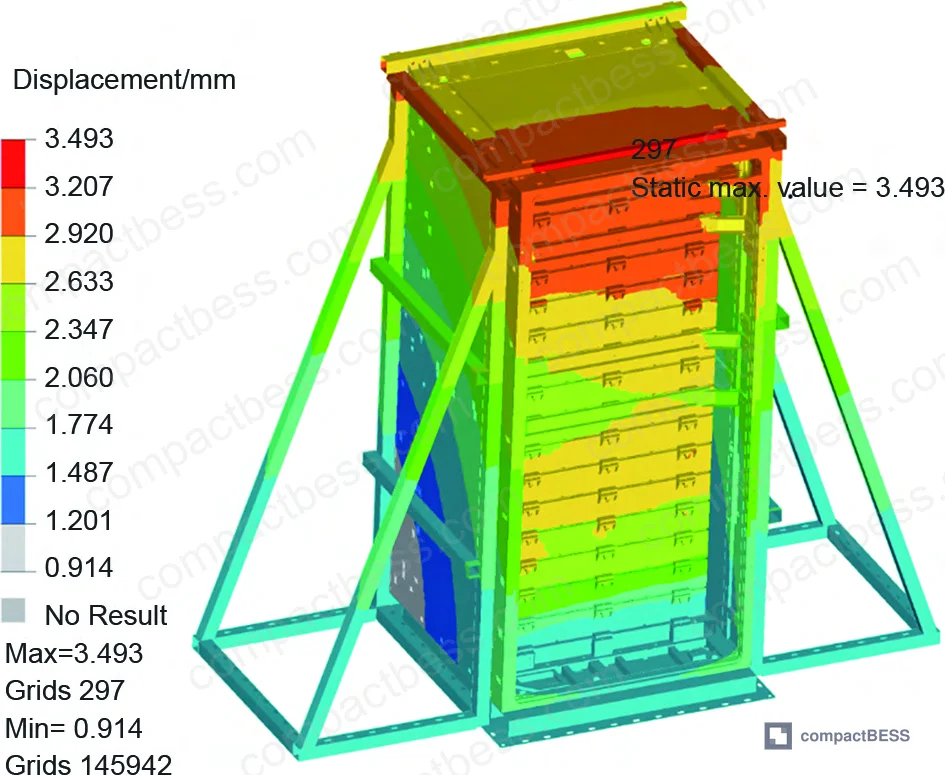
- Maximum cabinet displacement: 3.493 mm at cabinet top
- Maximum fixture stress: 159.5 MPa at fixture top cross-beam bolt connection
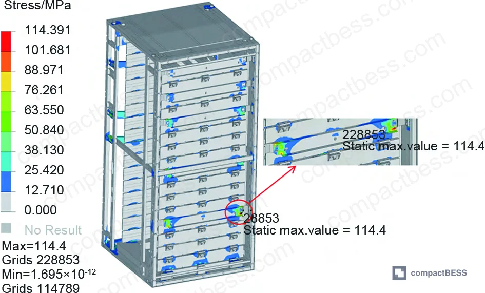
- Maximum cabinet stress: 114.4 MPa at lowest rear cross-beam connector
All stress values remained below yield strength for both materials (200 MPa for SPCC, 355 MPa for Q355). The simulation confirmed elastic behavior throughout. Crucially, the high-stress zones identified in the stress contour plots correlated directly with the wear and loosening locations observed in the physical test — particularly the fixture cross-beam bolts and the lower cabinet base fasteners.
A note on the simulation method’s limits: frequency-domain random vibration analysis is a linear method. It gives you statistical stress distributions — root mean square values across the PSD input — but it cannot predict cumulative fatigue damage, localized plastic deformation, or the time-history effects that drive fastener loosening. The bolt torque decay seen in the physical test is precisely the kind of result that linear FEA cannot reproduce. For final design validation, you need the physical test. The FEA tells you where to look.
Practical Guidance for Buyers #
If you’re qualifying a BESS cabinet supplier and vibration compliance is on your checklist, here’s what the data tells you to actually do.
First, require sweep frequency test reports with extracted natural frequencies and damping ratios — not just a pass/fail statement. The first-order frequencies for a cabinet in this mass and geometry class should fall in the 7–9 Hz range. If a supplier reports numbers well outside that range without explanation, push back on their boundary conditions and fixture design.
Second, add a post-test fastener torque audit to your acceptance criteria. The 54% torque decay at the base mounting bolt in this test would have gone undetected without a torque check. Specify minimum residual torque after test completion for all primary structural fasteners — and define what “primary” means clearly in your procurement spec.
Third, treat FEA modal validation error above 5% as a red flag during design reviews. A supplier who presents a structural analysis model without experimental validation data is giving you a model you cannot trust for transport risk assessment.
For transport-specific compliance, reference ISTA 3E for domestic long-haul truck profiles and cross-reference with IEC 62619 safety requirements for stationary applications. For pack-level structural design guidance, see our internal resource on busbar and interconnect design and pack enclosure and IP rating.
Frequently Asked Questions #
Q: What natural frequencies should I expect from a large BESS cabinet, and why does it matter for transport qualification?
A: For a cabinet in the 3,000–5,000 kg range with a steel welded structure, first-order natural frequencies typically fall between 7 and 10 Hz in both the longitudinal and lateral directions. The cabinet tested here measured 7.485 Hz (X) and 8.431 Hz (Y). These frequencies matter because road surface irregularities under highway truck transport generate broadband vibration energy with significant content in the 5–15 Hz range — directly overlapping the cabinet’s resonance band. If your transport route includes rough secondary roads or rail transfer, the excitation is even more concentrated in this range. A cabinet without proper structural damping or vibration isolation at mounting points will accumulate hidden damage at these resonance frequencies over long-haul routes.
Q: Is ISTA 3E the right test standard for BESS cabinet transport qualification, or should I be requiring something else?
A: ISTA 3E is a reasonable baseline for consolidated truck freight, and it’s appropriate for cabinets shipped as complete units. However, it only covers vertical (Z-direction) random vibration. It does not address horizontal excitation from cornering, braking, or multi-modal transfer (port crane lifts, rail car dynamics). For comprehensive qualification, you should supplement ISTA 3E with sinusoidal sweep tests in X and Y directions — exactly as done in this test program — and consider whether your specific shipping route warrants additional shock/drop testing per ISTA 2A or equivalent.
Q: What does a 54% bolt torque loss actually mean for field risk?
A: It means the fastener is no longer providing the clamping force it was designed to deliver. In this test, the base mounting bolt decayed from 50 N·m to 23 N·m after 2 hours of simulated truck transport. In the field, that same process happens over hours of road vibration before the cabinet even reaches the installation site. A loose base mounting bolt on a nearly 4-tonne cabinet creates unpredictable load paths, potential fretting damage at the joint interface, and — depending on installation design — a real risk of the cabinet shifting during secondary transport or handling. Require thread-locking compound or positive retention features on all primary structural fasteners as a standard procurement condition.
Q: Can FEA replace physical vibration testing for structural qualification?
A: No. FEA validates the design and tells you where to focus test instrumentation. It cannot reproduce fastener loosening, cumulative fatigue at welds, or nonlinear contact effects — all of which showed up in this physical test program. The FEA model here achieved under 5% error versus measured modal frequencies, which is good. But the bolt torque decay was a purely physical result that the linear frequency-domain simulation cannot predict. Use FEA to accelerate design iteration and identify high-stress regions; use physical testing for final qualification and acceptance.
Q: What internal design details most affect vibration performance in a BESS cabinet?
A: Cross-beam connector stiffness and fastener preload retention are the two highest-leverage parameters. The FEA in this study identified the lowest rear cross-beam connector as the highest-stress location in the cabinet structure under Z-direction random vibration (114.4 MPa peak). That’s the joint geometry you want to optimize first in any structural redesign. Beyond that, the damping ratio spread across sensor locations — from 0.048 to 0.076 depending on position — indicates that local compliance at module end plates and beam-to-frame connections has a meaningful effect on system-level dynamic response. Stiffer module retention and controlled contact at these interfaces will raise effective damping and reduce peak stress amplification.
Published by compactbess.com Technical Team | Request a sourcing quote
Content reviewed by michael.tan | © compactbess.com — All rights reserved. Unauthorized reproduction prohibited.


