

TL;DR #
If you’re still building your BESS procurement strategy around a binary choice between conventional liquid-electrolyte lithium-ion and fully solid-state cells, you’re already behind the curve. Semi-solid-state battery technology has moved from laboratory curiosity to a credible procurement option for large-scale stationary storage — and the specification profiles are different enough from either extreme that sourcing teams who don’t understand the architecture are routinely mismatching products to applications.
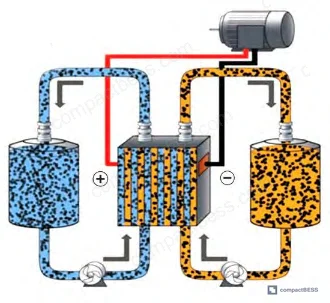
The core proposition is straightforward: semi-solid-state cells use a flowable electrode suspension — active material particles, conductive additives, and electrolyte combined into a slurry — circulated between storage tanks and a reaction chamber by pump. Ionic transfer happens across an ion-selective membrane; electrons travel the external circuit. What you get is the ionic conductivity advantage of liquid electrolyte combined with substantially improved structural stability compared to conventional liquid cells. That combination directly addresses the three failure modes that generate the most warranty claims in stationary BESS deployments: thermal runaway, dendrite-induced short circuits, and electrode delamination from volumetric cycling stress.
This article evaluates semi-solid-state technology from a procurement and qualification standpoint — what the performance data actually means for system selection, where the technology still has friction points, and how to avoid the specification traps that cost buyers months of rework.
Chemistry and Architecture: How Semi-Solid Compares to Liquid Li-Ion and LFP #
Honestly, most buyers over-specify energy density and under-specify system integration complexity when evaluating semi-solid-state cells. The theoretical specific energy of lithium-sulfur semi-solid configurations reaches 2,600 Wh/kg — a figure that gets quoted in sales conversations far more often than it gets delivered in qualified product. For procurement purposes, the more relevant performance window sits in the practical operating range of validated semi-solid lithium-ion systems, which currently demonstrate meaningfully higher utilization of active electrode material than fixed solid-electrode designs, due to the flowable suspension’s ability to continuously refresh reaction interfaces.
The three primary semi-solid chemistries relevant to B2B stationary storage procurement are:
| Chemistry | Theoretical Specific Energy | Thermal Runaway Risk | Scale-Up Mechanism | Primary Application Fit |
|---|---|---|---|---|
| Semi-solid Li-ion | High (suspension-enhanced) | Reduced vs. conventional liquid Li-ion | Adjustable tank volume | Grid-scale, EV fleet charging |
| Semi-solid Li-S | Up to 2,600 Wh/kg (theoretical) | Low-moderate | Large-volume slurry tanks | Renewable storage, off-grid |
| Semi-solid Zn-based | Moderate | Very low, no thermal runaway | Flow-battery-style scaling | Peak shaving, emergency backup |
The zinc-based semi-solid systems deserve more attention from procurement teams than they currently receive. Zinc is abundant, the electrochemical potential is moderate and stable, and the thermal runaway risk profile is substantially lower than any lithium-based system. For applications where energy density is secondary to safety and total cost of ownership — grid frequency regulation, emergency backup — zinc semi-solid is worth a formal qualification run.
Semi-solid lithium-ion addresses the two structural failure modes that plague conventional liquid-electrolyte cells in cycling applications: dendrite growth and electrode volume change during charge-discharge. The ion-selective membrane limits dendrite propagation, while the suspension’s flowability physically accommodates the volumetric expansion that cracks fixed solid electrodes. That translates directly to cycle life and capacity retention figures that outperform conventional liquid Li-ion in long-duration stationary applications.
For compliance framing, semi-solid cells for stationary BESS must still satisfy IEC 62619:2022 — Safety requirements for secondary lithium cells and batteries for use in industrial applications, and transport qualification runs through UN 38.3 — Transport of Dangerous Goods: Manual of Tests and Criteria. Zinc-based systems with water-based electrolytes may have a significantly simplified compliance pathway for certain jurisdictions.
Technical Challenges: Where Qualification Programs Actually Find Problems #
In supplier qualification programs for semi-solid-state cells, the failure patterns cluster around three areas — and none of them are the ones most procurement teams are stress-testing.
Suspension stability under long-term cycling is the first failure class. The electrode suspension consists of active material particles, conductive additives, and electrolyte. Over extended cycling, active particles settle, agglomerate, or develop non-uniform interfaces. In supplier qualification, we saw samples where uneven conductive additive distribution created localized high-resistance zones — the cells passed initial capacity tests but showed accelerated internal resistance growth after 200 cycles. Capacity fade and internal resistance increase were the observable outputs; the root cause was suspension phase separation that standard incoming inspection doesn’t catch.
Temperature sensitivity compounds this. At elevated temperatures, solvent evaporation from the suspension accelerates. At low temperatures, suspension viscosity increases sharply, which raises pump load and reduces ionic mobility. Neither extreme is immediately catastrophic, but both degrade performance in ways that standard cell-level testing at 25°C won’t reveal. Any qualification protocol for semi-solid cells should include suspension stability testing across the full operating temperature range of the intended deployment — not just electrochemical cycling at standard conditions.
Interface impedance at high C-rates is the second critical failure class. The solid-liquid interface between electrode particles and electrolyte generates impedance that becomes dominant under high-rate charge-discharge conditions. Polarization effects at the interface reduce kinetic performance precisely when it matters most — during demand peaks or rapid renewable input absorption. Local lithium dendrite nucleation and parasitic side reactions are the downstream consequences.
Most procurement teams don’t realize that IEC 62660-1 — the performance testing standard for lithium-ion cells used in electric vehicles — was structured around fixed solid-electrode assumptions. Its test protocols don’t fully characterize flow-dependent semi-solid cell behavior, particularly the interaction between flow rate, suspension homogeneity, and impedance under dynamic load profiles. Industry standardization for semi-solid-specific testing methods is still catching up, which means your qualification protocol needs to be built in-house or with a qualified test lab rather than relying entirely on standard certification.
System integration complexity is the third area where procurement teams consistently underestimate scope. Unlike a conventional cell stack, a semi-solid system requires suspension storage tanks, circulation pumps, flow path manifolds, pressure regulation, and a BMS with flow rate and temperature monitoring — not just voltage and current. The BMS must manage SOC, temperature, flow rate, and local overcharge/overdischarge conditions simultaneously. Pump and manifold reliability directly determines system uptime; these are mechanical components with wear characteristics and maintenance intervals that pure-electrochemical BESS systems don’t have.
Relevant safety and regulatory standards for system-level qualification include UL 9540 — Standard for Energy Storage Systems and Equipment for complete system certification, particularly relevant for North American market entry.
Optimization Strategies for Specification and Sourcing #
The technical optimization literature on semi-solid cells converges on four levers that are directly relevant to what you should be requiring from suppliers in RFQ specifications.
Conductive additive and electrolyte formulation. The ratio of conductive additive to active material in the suspension is not a secondary specification — it is a primary determinant of cycle life and rate capability. Particle size, morphology, and dispersion uniformity of the conductive additive determine the connectivity of the electron transport network within the flowing suspension. Electrolyte solvent type and salt concentration control ionic solubility and migration rate. Ask suppliers to provide data on suspension conductivity as a function of temperature, not just room-temperature ionic conductivity of the bulk electrolyte.
Dispersion and circulation process controls. Ultrasonic dispersion, high-shear mixing, and controlled surfactant addition are the primary methods used to prevent active particle agglomeration during manufacturing. On the system integration side, flow path geometry and pump curve selection determine whether the suspension maintains uniform velocity across the reaction chamber or develops dead zones where material settles. Intelligent flow control with real-time pressure feedback is the difference between a system that maintains performance over 1,000 cycles and one that degrades progressively after 300.
Interface engineering. Functional coatings on electrode particle surfaces — fluoride-based, oxide-based, or polymer film — reduce the solid-liquid interface impedance and suppress parasitic side reactions. This is an area where suppliers differentiate significantly, and it’s worth requesting impedance spectroscopy data (EIS measurements) under multiple temperature and SOC conditions rather than accepting single-point resistance values.
Intelligent BMS and energy management. For semi-solid systems, the BMS specification should explicitly include flow rate monitoring, suspension temperature gradients, and local SOC balancing across the reaction chamber volume. Predictive thermal management and anomaly alerting are minimum requirements for grid-connected stationary applications.
Procurement teams working on EU market qualification should also verify alignment with EU Battery Regulation 2023/1542, which establishes mandatory due diligence, carbon footprint declaration, and end-of-life requirements for industrial batteries above 2 kWh — a threshold that all stationary semi-solid systems will exceed.
For buyers evaluating these cells for portable or mobile applications, additional context on energy density tradeoffs across cell formats is available in our guide to cell formats and form factors.
Practical Guidance for Buyers #
If you’re evaluating semi-solid-state cells for a stationary BESS project, start your qualification with suspension stability testing — not energy density benchmarking. The theoretical performance ceiling is well-documented; what differentiates suppliers is whether their suspension formulation maintains homogeneity after 500+ cycles under your actual operating temperature profile.
Request EIS data across temperature and SOC ranges, not just initial internal resistance values. Require suppliers to disclose conductive additive particle size distribution and the dispersion process used during manufacturing. For system-level integration, get the full BMS specification including flow monitoring parameters and ask what happens to the system if the circulation pump loses pressure mid-cycle.
Don’t select a zinc semi-solid system based on lithium-ion sizing assumptions — the scaling mechanism is different, the compliance pathway is different, and the maintenance profile is different. Each chemistry requires its own evaluation framework.
For deeper context on how chemistry selection connects to SOC estimation and degradation modeling in real deployed systems, the SOC estimation methods guide covers the BMS-side implications in detail.
Finally: if a supplier can’t provide cycle-life data with capacity retention figures at multiple temperatures and C-rates, that’s a disqualifying gap — not a negotiating point.
Frequently Asked Questions #
Q: What is the main structural difference between a semi-solid-state battery and a conventional liquid-electrolyte lithium-ion cell?
A: In a conventional lithium-ion cell, the electrodes are fixed solid structures. In a semi-solid system, the electrode material is formulated as a flowable suspension — active particles, conductive additives, and electrolyte mixed into a slurry — which is stored in tanks and continuously circulated through a reaction chamber by pump. Ionic transfer occurs across a selective membrane separating the positive and negative suspensions. This architecture gives semi-solid systems a capacity-scaling advantage (add more tank volume) and reduces the dendrite and electrode delamination failure modes associated with fixed solid electrodes, but it introduces mechanical complexity — pumps, flow paths, pressure management — that conventional cells don’t have.
Q: Is the 2,600 Wh/kg figure for lithium-sulfur semi-solid cells achievable in commercial procurement?
A: Not at present. That figure is the theoretical specific energy for the lithium-sulfur electrochemical couple under ideal conditions. In practice, the sulfur cathode has poor electronic conductivity, and polysulfide dissolution into the electrolyte causes capacity fade in conventional Li-S designs. Semi-solid Li-S configurations improve on this by dispersing sulfur in a conductive slurry, but commercially available cells are not close to theoretical specific energy. Treat 2,600 Wh/kg as a long-term directional target, not a current procurement specification.
Q: Which certification standards apply to semi-solid-state batteries for grid-connected stationary storage?
A: The primary standards framework for industrial stationary applications includes IEC 62619 for cell-level safety, UL 9540 for complete energy storage systems (North America), and EU Battery Regulation 2023/1542 for EU market compliance. UN 38.3 applies to transport of battery modules regardless of destination market. Semi-solid-specific testing standards are still developing — current standards were written with fixed solid-electrode assumptions — so your qualification protocol will need to supplement standard certification with application-specific testing, particularly for suspension stability and flow-dependent performance.
Q: How should the BMS specification differ for a semi-solid system versus a conventional BESS?
A: A conventional BESS BMS monitors voltage, current, temperature, and SOC per cell or module. A semi-solid BMS must additionally monitor suspension flow rate, pump pressure, suspension temperature gradients across the reaction chamber, and local SOC distribution within the flow volume. Without flow-rate feedback, the BMS cannot detect early-stage suspension settling or pump degradation — both of which precede capacity fade by dozens of cycles. Treat flow monitoring as a non-negotiable specification item, not an optional feature.
Q: Are zinc-based semi-solid systems viable for peak-shaving applications today?
A: Viable, yes — but qualification effort is still significant. Zinc semi-solid offers a genuinely lower thermal risk profile than any lithium-based system and benefits from abundant, low-cost raw materials. The scaling mechanism is well-suited to peak-shaving duty cycles. The gap is cycle-life data under real operating conditions and supplier maturity — the commercial supply base is narrower than for lithium-ion.
Published by compactbess.com Technical Team | Request a sourcing quote
Content reviewed by dr.james.okafor | © compactbess.com — All rights reserved. Unauthorized reproduction prohibited.


