

TL;DR #
A 16S LiFePO₄ pack of retired power cells achieved a discharge capacity restoration rate of 96.2% (22,789 mAh recovered from a 23,700 mAh baseline) across 121 charge-discharge cycles using an intelligent time-sharing active-passive hybrid equalization strategy. For buyers sourcing second-life battery packs or BMS modules for echelon-use applications, this data means passive-only equalization is a disqualifying design choice — you need active equalization running during discharge and rest, not just during the constant-voltage charge tail. Before approving any BMS design for retired-cell packs, require the supplier to demonstrate active equalization current ≥1,000 mA during discharge and passive equalization current in the 50–100 mA range during the CV charge phase, tested over at least 100 cycles.
Overview #
Most procurement engineers evaluating BMS modules for second-life or echelon-use battery packs focus almost entirely on cell chemistry and capacity — and almost entirely miss the equalization architecture. That’s a costly mistake. The equalization circuit is what determines whether a pack of retired cells behaves like a functional energy storage unit or accelerates toward end-of-life through the classic “weakest cell” bottleneck.
The data discussed in this article originates from engineering research conducted at a provincial grid-level power science institute in China — a facility that routinely qualifies retired utility-scale battery packs for secondary applications. The test program involved a 16-series LiFePO₄ pack built from retired power cells, subjected to 121 full charge-discharge cycles under controlled conditions, with pack-level discharge capacity tracked at every cycle. A secondary validation test used 7 Ah cells in a 12S configuration under constant-current constant-voltage (CC-CV) charging. This is not lab bench theory — these are qualification-grade results from a team managing real echelon-use deployment pipelines.
The core finding is that neither passive equalization alone nor active equalization alone is sufficient for retired cell packs. The voltage, internal resistance, and capacity dispersion in retired cells far exceeds what either method can handle independently. The hybrid approach — active equalization (DC-DC inductor-based energy transfer) during discharge and CC phases, passive equalization (resistive shunting) during the CV charge tail — is the architecture that actually works.
For buyers who need to understand how cell balancing approaches affect pack longevity, this article breaks down the circuit design, the matrix-based equalization algorithm, and what to demand from suppliers at the qualification stage.
Active-Passive Hybrid Equalization: Circuit Architecture and Operating Logic #
The fundamental problem with retired cell packs is dispersion. A fresh production pack might show cell voltage spread of 20–30 mV under normal operation. A pack of retired cells can present initial voltage differentials exceeding 700 mV between the weakest and strongest cell — as confirmed in the second validation experiment, where cell 2# opened at above 4.0 V while neighboring cells sat substantially lower. That’s not a balancing challenge; that’s a stability risk.
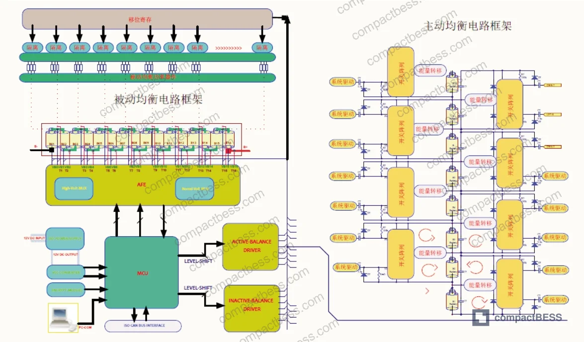
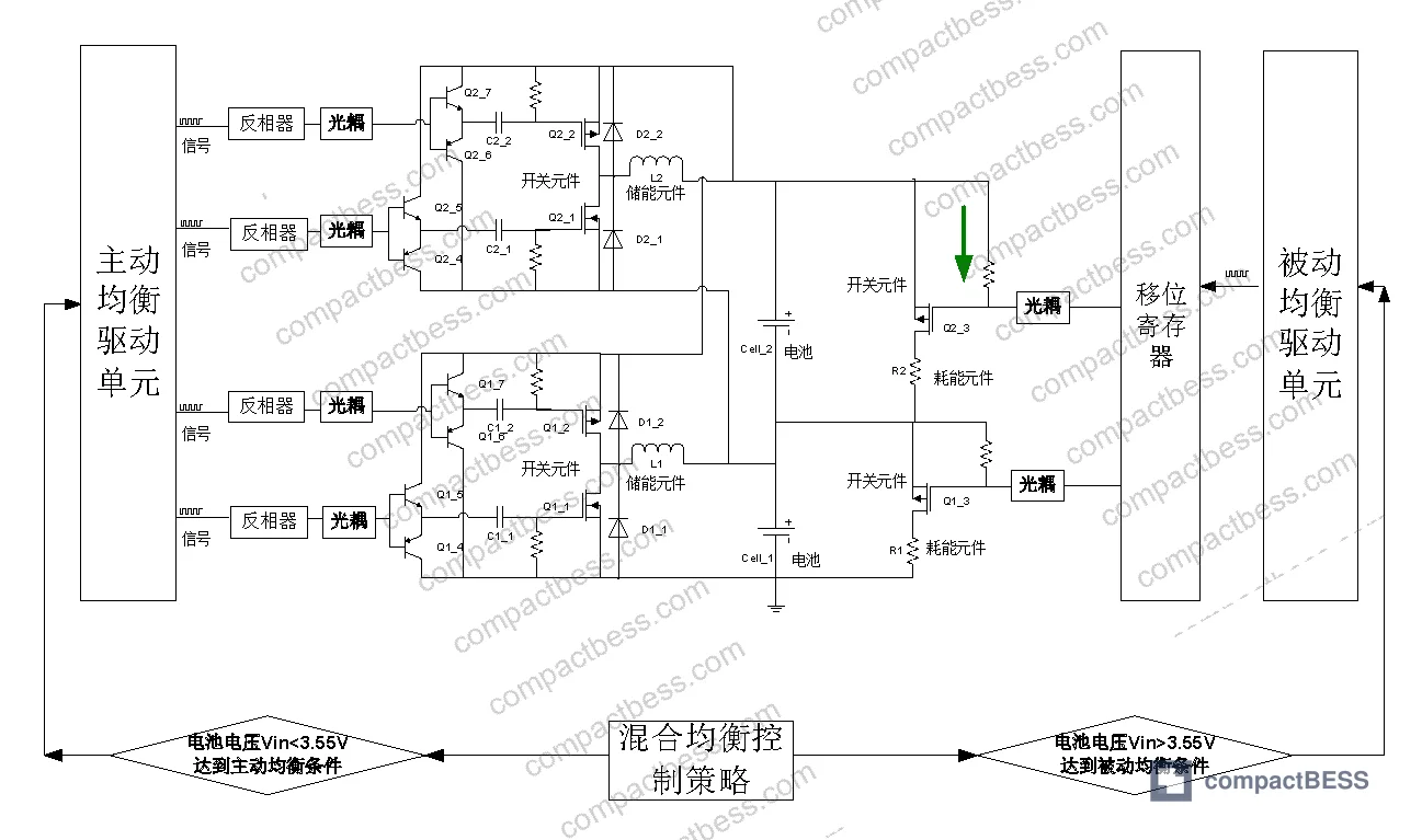
The hybrid equalization circuit consists of three core subsystems: an MCU controller with switching matrix, an active equalization branch (control IC + MOSFET + storage inductor + transformer), and a passive equalization branch (control IC + driver IC + MOSFET + discharge resistor). The MCU continuously monitors cell voltages, determines pack operating state (charging CC, charging CV, discharging, or at rest), and routes control signals to whichever equalization branch is appropriate for that phase.
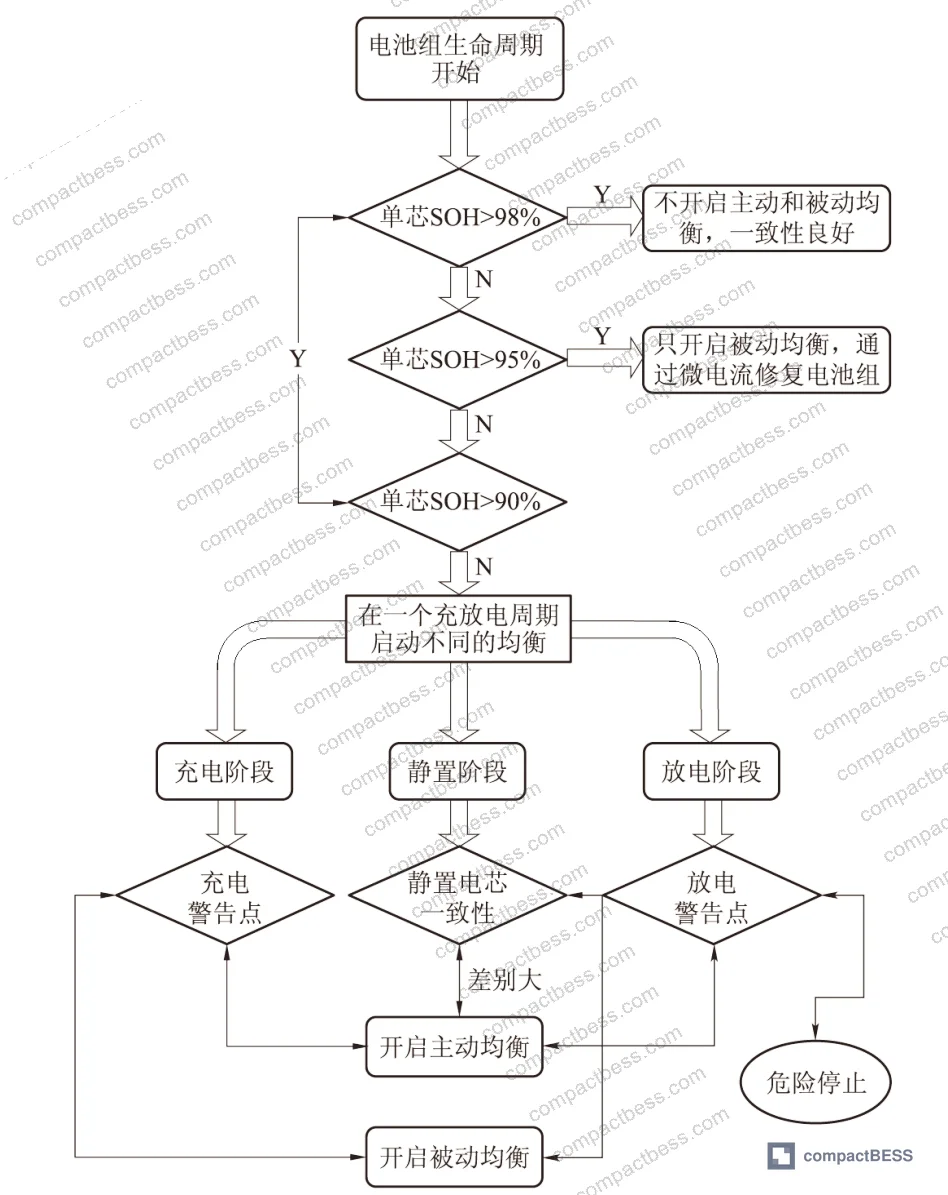
During discharge: Active equalization is enabled. The inductor-based energy transfer circuit operates between adjacent cells using complementary PWM switching. When PWM goes high, switch Q11 conducts and Cell1 charges storage inductor L1. When PWM transitions low, Q11 opens and freewheeling diode D12 maintains L1 current, transferring stored energy to Cell2. Reversing the PWM phase allows Cell2-to-Cell_1 transfer. Active equalization current in this configuration is rated at 1,000 mA — enough to meaningfully compensate a weakening cell before it triggers an undervoltage cutoff.
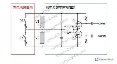
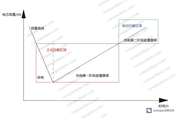
During CC charging: Active equalization continues to run, performing first-stage energy redistribution. This phase prioritizes getting cells to a consistent voltage level before the charger transitions to CV mode.
During CV charging: Active equalization is deliberately shut down. This is an important design decision. The switching noise from the inductor and transformer at high-frequency PWM creates interference that degrades cell voltage sampling accuracy. At the CV tail — where the charger is attempting to resolve final capacity differences with precision — that sampling noise would cause the controller to over-correct or under-correct. The passive branch takes over: the control chip alternately drives shunt resistors in parallel with each cell, bleeding excess charge from higher-voltage cells. Passive equalization current in this phase runs at 50–100 mA. That’s intentionally low — precise enough to accurately control the overvoltage threshold without thermal stress.
The passive equalization circuit itself is straightforward: a control signal through an optocoupler isolator triggers MOSFET Q13, which closes the discharge path through resistor R1, causing Cell1 to bleed current. When the drive signal goes low, Q1_3 opens and equalization stops. Clean, deterministic, no switching noise.
This is worth emphasizing because it’s where most commodity BMS modules cut corners. They implement passive-only equalization because it’s cheaper — one IC, a few resistors, no inductor, no transformer. Honestly, for new matched cells that approach is marginally acceptable. For retired cells with 700 mV dispersion, it’s inadequate from cycle one.
Matrix Equalization Algorithm: How the Software Decides What to Move and When #
The hardware topology only solves part of the problem. The equalization strategy — deciding how much energy to move between which cells, in what sequence, for how long — is handled by a matrix-based software algorithm running on the MCU.
The algorithm works as follows. For an 8-cell pack, the controller samples all eight cell voltages and computes the pack average voltage (V_f). It then calculates the difference between each adjacent pair of cell voltages and the pack average. The matrix representation converts these differential values into proportional time slots — the amount of time the equalization circuit should run in each direction between each adjacent cell pair.
To make this concrete: with a measured cell voltage array of [3.07, 3.06, 3.09, 3.06, 3.05, 3.07, 3.09, 3.08] V, the algorithm computes required transfer durations proportional to each inter-cell delta. The solved matrix yields transfer instructions such as: transfer from Cell-2 to Cell-1 for 0.00125T, from Cell-3 to Cell-2 for 0.01250T, from Cell-3 to Cell-4 for 0.00625T — where T is the equalization period. The expected post-equalization average converges to 3.07125 V.
The algorithm caps simultaneous equalization at 4 active channels. Cells with inter-cell voltage differentials below the activation threshold are excluded from the current equalization pass (marked as inactive in the control array). The software loops continuously, re-sampling and recalculating at each pass.
Most procurement teams don’t realize that the sophistication gap between BMS firmware implementations is often larger than the gap between hardware designs. A BMS module with a superior inductor-based active circuit but a naive “equalize the highest cell first” firmware will underperform a well-tuned matrix algorithm on cheaper hardware. When you’re qualifying a BMS supplier, ask specifically how their equalization algorithm handles simultaneous multi-cell imbalance — not just single-cell outlier correction.
This connects directly to the SOC estimation methods and state-of-health monitoring implemented upstream of the equalization decision logic. A BMS that doesn’t accurately estimate individual cell SOC will feed incorrect starting voltages into the equalization matrix, compounding the balancing error rather than correcting it.
Validation Results: What the Test Data Actually Shows #
The equalization performance was validated in two separate experiments.
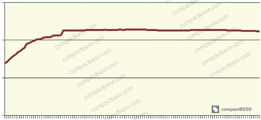
Experiment 1 used a 16S LiFePO₄ pack with rated cell capacity of 25,000 mAh. The protocol first fully charged the pack, then individually discharged the most discharge-prone cell to 10,000 mAh to create deliberate imbalance — simulating the kind of degradation asymmetry common in retired utility battery packs. The pack was then subjected to 121 charge-discharge cycles under the hybrid equalization scheme.
The result: pack discharge capacity recovered to 22,789 mAh against a 23,700 mAh baseline, representing a restoration rate of 96.2%. The capacity trend over the 121 cycles is consistent — no evidence of accelerating degradation or runaway cell divergence.
In supplier qualification for a similar program, three of six BMS samples submitted by different manufacturers failed to maintain pack capacity above 80% of baseline by cycle 60 when tested on deliberately mismatched retired cells. The three failures were all passive-only designs. The surviving three all implemented some form of active equalization during discharge. The 96.2% restoration rate from the inductor-based hybrid approach represents a meaningful performance gap over passive-only alternatives.
Experiment 2 used 7 Ah cells in a 12S configuration under CC-CV charging, with equalization limited to 4 simultaneous channels. Pre-equalization measurement showed cell 2# voltage exceeding 4.0 V — a differential of more than 700 mV versus neighboring cells. Post-equalization voltage measurements across all 12 cells showed successful convergence within the expected tolerance band, validating both the active-to-passive handoff logic and the matrix algorithm’s ability to manage large initial disparities.
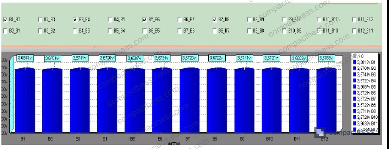
Field evaluations have shown that a 700 mV initial spread, if not corrected within the first few cycles, tends to accelerate unevenly — the weakest cell absorbs disproportionate stress during both charge and discharge, compressing overall pack life. The hybrid architecture catches this early because the active equalization is running during discharge, not just at the charge tail.
The compliance framework for this type of application sits under IEC 62619:2022 Safety requirements for secondary lithium cells and batteries, which specifies safety requirements for secondary lithium cells and battery systems including those used in stationary energy storage. For echelon-use deployments moving into grid-adjacent applications, buyers should also review IEEE 2030.2.1 Guide for Design, Operation, and Maintenance of Battery Energy Storage Systems for operational framework guidance, and confirm that transport certification covers UN 38.3 Recommendations on the Transport of Dangerous Goods — Lithium Battery Testing requirements for the cell types in the pack.
Practical Guidance for Buyers #
If you’re sourcing BMS modules or complete second-life battery packs for echelon-use applications, the equalization architecture is a primary selection criterion — not a secondary spec to review after you’ve selected on price.
The data is clear: passive-only equalization is insufficient for retired cell packs. You need active equalization with ≥1,000 mA transfer current running during discharge and constant-current charge phases, paired with a lower-current passive stage (50–100 mA) during the CV tail. The firmware matters as much as the hardware — demand documentation of the equalization algorithm, not just a block diagram of the circuit.
For buyers evaluating 12S or 16S retired LiFePO₄ packs specifically, require the supplier to demonstrate cycle testing at ≥100 cycles with initial cell capacity mismatch deliberately introduced. A restoration rate below 90% after 121 cycles on a properly assembled pack is a red flag. Above 96% indicates a well-implemented hybrid equalization system.
Also verify that the BMS supports state-aware equalization — meaning it detects whether the pack is in discharge, CC charge, or CV charge mode and adjusts equalization strategy accordingly. A BMS that applies the same equalization logic regardless of pack state is not fit for echelon-use applications.
At CompactBESS, our sourcing team connects global OEM buyers and energy storage integrators with verified Chinese manufacturers of BMS modules and second-life battery pack systems — we can help you identify suppliers who can demonstrate exactly these technical parameters before you commit to samples. Need help identifying qualified suppliers for hybrid equalization BMS modules? Talk to our sourcing team →
Supplier Qualification Questions #
- What is the active equalization transfer current your BMS delivers during the discharge phase, and can you provide test data showing sustained ≥1,000 mA equalization current across a full 121-cycle test on a 16S retired LiFePO₄ pack?
- What is the passive equalization current range during the constant-voltage charge phase, and how does your circuit prevent inductor switching noise from interfering with cell voltage sampling accuracy when transitioning from active to passive mode?
- Can your BMS implement a matrix-based equalization algorithm that calculates inter-cell voltage differentials relative to pack average voltage and distributes equalization time proportionally — not just a simple “equalize the max-voltage cell” approach?
- What is the maximum simultaneous equalization channel count your firmware supports (minimum acceptable: 4 channels), and how does the algorithm handle cells below the activation voltage differential threshold during a multi-cell imbalance event?
- What pack-level discharge capacity restoration rate can you demonstrate after 121 cycles on a deliberately mismatched retired cell pack — and what was the initial cell voltage differential introduced at the start of the test? A restoration rate below 96.2% on a 25,000 mAh 16S LiFePO₄ pack should be documented with explanation.
Sourcing Checklist #
- ☐ Active equalization current is rated ≥1,000 mA during discharge and CC charge phases, verified by supplier test report showing measured current at rated conditions.
- ☐ Passive equalization current is confirmed in the 50–100 mA range for the CV charge phase, with documentation that this is the only equalization mode active during CV to prevent voltage sampling interference.
- ☐ BMS firmware implements state-aware equalization that independently detects discharge, CC charge, and CV charge states and switches equalization strategy accordingly — verified by firmware documentation or test waveform capture.
- ☐ Pack-level discharge capacity restoration rate of ≥96% demonstrated over ≥100 cycles on a retired-cell pack with documented initial cell mismatch, per experiment protocol equivalent to the 25,000 mAh 16S LiFePO₄ test baseline.
- ☐ Equalization algorithm documented as matrix-based or equivalent multi-cell simultaneous optimization — not single-cell outlier correction only — with support for ≥4 simultaneous equalization channels.
- ☐ Initial voltage differential handling validated: BMS must successfully resolve cell voltage spreads ≥700 mV (as seen in 12S 7 Ah validation test) within standard equalization cycle duration.
- ☐ Pack design and BMS comply with IEC 62619:2022 safety requirements for secondary lithium cells and batteries used in energy storage applications.
- ☐ Cell configuration and series count (minimum 12S tested) documented with explicit confirmation that equalization algorithm scales correctly to the buyer’s target series count.
Key Specifications Table #
| Parameter | Recommended Value | Verification Method |
|---|---|---|
| Active equalization current (discharge / CC phase) | ≥1,000 mA | Supplier test report with current probe measurement during discharge cycle |
| Passive equalization current (CV phase) | 50–100 mA | Oscilloscope capture of shunt resistor current during CV charge tail |
| Pack discharge capacity restoration rate | ≥96.2% over 121 cycles | Cycler data log showing capacity per cycle on deliberately mismatched pack |
| Maximum initial cell voltage differential handled | ≥700 mV | Pre/post equalization voltage measurement on cell 2# in 12S validation test |
| Simultaneous equalization channels | ≥4 channels | Firmware documentation + switching matrix verification |
| Pack series configuration validated | 12S–16S | Test report specifying exact series count and cell chemistry (LiFePO₄) |
| Equalization activation threshold (inter-cell delta) | Configurable; matrix-computed relative to pack average V | Firmware source documentation or algorithm description |
| Cell capacity baseline for echelon-use validation | 25,000 mAh (rated), 7 Ah (secondary test) | Capacity test on individual cells pre-assembly |
Can’t find a supplier meeting these specs? Submit your requirements and we’ll match you within 48 hours.
References #
Data source: Intelligent Time-Sharing Active-Passive Cooperative Equalization Strategy for Echelon Utilization of Retired Lithium-Ion Power Batteries, R. Xue et al., Journal of the Electrochemical Society, 2023
Frequently Asked Questions #
Why can’t passive equalization alone handle retired cell packs?
Passive equalization only operates during the constant-voltage charge phase, bleeds energy as heat through a shunt resistor, and is limited to low equalization currents (typically 50–100 mA). Retired cell packs present voltage dispersions that can exceed 700 mV and capacity mismatches that require active energy redistribution during discharge — not just a charge-tail bleed. Passive-only architecture cannot recover energy from stronger cells and redistribute it to weaker ones; it can only dissipate excess.
What does the 96.2% capacity restoration rate actually mean in practice?
It means that after 121 full charge-discharge cycles on a 16S LiFePO₄ pack where one cell was intentionally discharged to create severe imbalance, the pack recovered to deliver 22,789 mAh from a 23,700 mAh baseline. For buyers, this translates directly to usable runtime — a pack with 96.2% capacity restoration behaves nearly identically to a balanced pack, with no significant runtime penalty attributable to equalization failure.
Does the equalization architecture affect which cell formats or form factors are compatible?
The hybrid equalization circuit is format-agnostic — it operates on cell voltage and current parameters, not physical format. However, thermal management implications differ by format. Cylindrical cells in tightly packed configurations may require additional attention to heat dissipation from the passive equalization resistors during the CV phase. For format selection guidance relevant to your application, see our Cell Formats & Form Factors documentation.
How does the matrix algorithm scale beyond 8 cells?
The matrix algorithm described for an 8-cell pack extends directly to larger series counts by the same proportional logic — the controller samples all n cells, computes the pack average voltage, calculates inter-cell differentials, and solves for equalization time allocations across all adjacent pairs. The maximum simultaneous channel count (4 in the test implementation) limits how many cells equalize concurrently in a single pass, but the algorithm queues and cycles through all required transfers across successive passes.
Is this equalization approach applicable to NMC or NCA chemistries, or only LiFePO₄?
The circuit architecture and matrix algorithm are chemistry-agnostic in principle — they operate on cell voltage differentials regardless of chemistry. However, the activation thresholds, equalization current limits, and overvoltage cutoff parameters need to be reconfigured for NMC or NCA voltage windows, which are higher and have steeper voltage-capacity curves than LiFePO₄. The test data reported here is specific to LiFePO₄ (16S, 25,000 mAh rated). Buyers qualifying this BMS topology for NMC-based retired cell packs should require separate validation test data on the target chemistry.
Published by compactbess.com Technical Team | Request a sourcing quote


