

TL;DR #
In controlled simulation on a 50 kWh mobile energy storage unit, a dual Extended Kalman Filter (DEKF) model achieved SOC estimation error as low as 0.3% on charge cycles and maintained SOH readings above 99.91% across three resistance-variation cycles — outperforming single EKF on most charge/discharge conditions. For buyers specifying intelligent BMS in mobile BESS procurement, this means filter architecture directly determines state-estimation accuracy, and “we use EKF” from a supplier is not a sufficient answer. Ask specifically whether their BMS implements joint state-and-parameter estimation (dual-loop EKF or equivalent) before approving a BMS design.
Overview #
Most procurement teams treat BMS state-estimation capability as a checkbox — SOC, SOH, and done. That’s a mistake that costs money in premature cell replacement and missed thermal events. The engineering reality is that SOC accuracy depends heavily on whether internal resistance and capacity are being co-estimated in real time, or whether the BMS is running a simplified single-filter loop that ignores parameter drift.
The analysis underpinning this article was conducted by engineers at a grid-connected power supply bureau working on mobile BESS units deployed for substation maintenance — a demanding field application where the battery cannot be taken offline for calibration and must deliver reliable state data across partial-state-of-charge operation. The simulation platform used a validated second-order RC equivalent circuit model on a 50 kWh LFP pack, with Matlab-based verification comparing single EKF against dual Extended Kalman Filter (DEKF) performance across multiple charge/discharge cycles. This field-oriented context matters: the findings aren’t from a lab cycling a single 18650 cell at constant temperature. They’re from a systems-level model designed around real grid-maintenance duty cycles.
For buyers sourcing SOH and RUL prediction capability in compact BESS or industrial BMS modules, the architecture choices described here map directly to supplier differentiation criteria.
Dual EKF Architecture and SOC Estimation Accuracy #
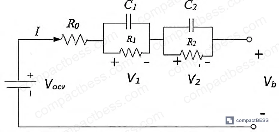
The core of this evaluation is a second-order RC equivalent circuit model. The battery terminal voltage is expressed as a function of open-circuit voltage (OCV), ohmic resistance R₀, and two RC branch voltages (V₁, V₂). The state vector tracks SOC, V₁, and V₂; the parameter vector tracks R₀ and capacity Cₚ simultaneously. This separation is the architectural point that matters.
In the DEKF implementation, EKFₓ handles fast-changing states (SOC, RC voltages) while EKFθ handles slowly evolving parameters (internal resistance, capacity). The two filters run in parallel and feed each other — SOC estimates use the current R₀ estimate rather than a fixed nominal value, which eliminates a systematic error source that plagues single-filter implementations.
Simulation results on the 50 kWh test unit:
| Metric | EKF (single) | DEKF (dual) | Improvement |
|---|---|---|---|
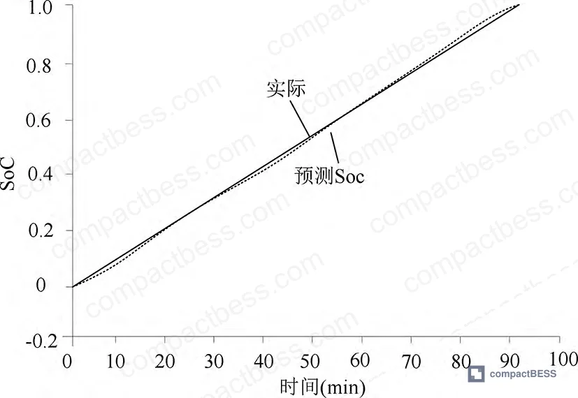
| Charge cycle SOC absolute deviation (Cycle 1) | 0.0094 | 0.0059 | 37% lower |
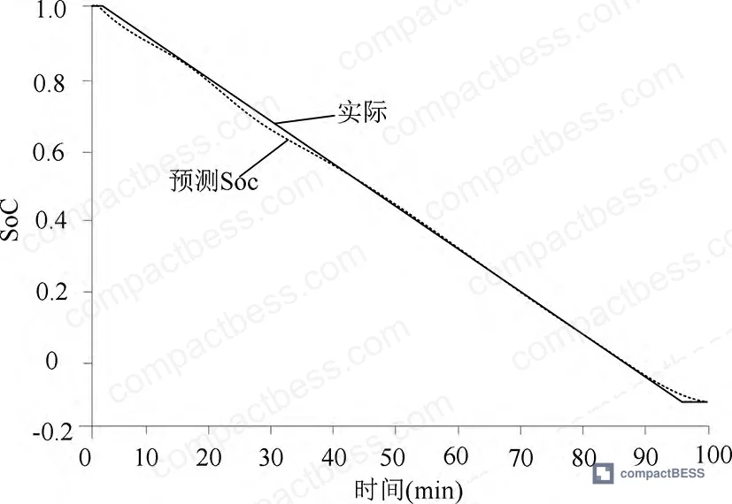
| Discharge cycle SOC absolute deviation (Cycle 1) | 0.0014 | 0.0019 | Slight DEKF variance |
| Charge cycle deviation (Cycle 2) | 0.0032 | 0.0019 | 41% lower |
| Discharge cycle deviation (Cycle 2) | 0.0058 | 0.0045 | 22% lower |
| Charge cycle deviation (Cycle 3) | 0.0105 | 0.0147 | EKF marginal advantage |
| Discharge cycle deviation (Cycle 3) | 0.0087 | 0.0078 | 10% lower |
The headline finding: charge-cycle SOC estimation error sits at 0.3%, and battery voltage error at 0.13%, with DEKF. On discharge, SOC error is 0.58% and voltage error drops to 1.05×10⁻⁴. DEKF performs better on most cycles, with Cycle 3 charge being the one exception — likely attributable to parameter convergence lag in early cycling, not a structural weakness.
Honestly, most buyers over-specify SOC accuracy at ±1% without understanding whether the BMS can actually sustain that across varying internal resistance conditions. A BMS quoting ±1% SOC accuracy based on fresh-cell characterization will degrade significantly as internal resistance increases with age — exactly the scenario the DEKF co-estimation architecture is designed to handle.
SOH Estimation: Capacity Fade and Internal Resistance Tracking #
SOH is computed two ways in this model, and both matter for procurement specification.
Capacity-based SOH:
SOH = (Cᵢ / C₀) × 100%, where Cᵢ is the DEKF-estimated current capacity and C₀ is nominal rated capacity. Across three simulated cycles at 1,400 Ah, SOH remained at 100% — confirming model convergence on a healthy cell, not battery degradation in the test itself.
Resistance-based SOH:
SOH = (Reol − Rᵦ) / (Reol − Rₙ) × 100%, where R_eol is defined as 1.6× the measured internal resistance Rᵦ, and Rₙ is the as-new internal resistance. Resistance-variation results:
| Cycle | Internal Resistance (Ω) | SOH (%) |
|---|---|---|
| 1 | 0.030073 | 99.91 |
| 2 | 0.030042 | 99.96 |
| 3 | 0.030005 | 99.98 |
The resistance values are deliberately varied to test model sensitivity, and the SOH tracking follows the trend correctly — higher resistance yields lower SOH, with 99.91% as the floor in this test range. The end-of-life threshold is set at 1.6× nominal internal resistance, which is a defensible boundary for LFP chemistry under field conditions.
Industry observation: most procurement teams don’t realize that SOH thresholds for field replacement decisions vary significantly by application — grid-connected BESS operators often use 80% capacity as the retirement trigger, while some mobile/backup applications run cells to 70% before replacement. The internal resistance method provides a faster-responding early warning signal because resistance increases precede measurable capacity fade. A BMS that only reports capacity-based SOH is giving you lagging data. The SOH & RUL Prediction methodology directly impacts asset lifecycle cost estimates that procurement teams are often asked to validate before contract award.
Safety Architecture: What the BMS Must Protect Against #
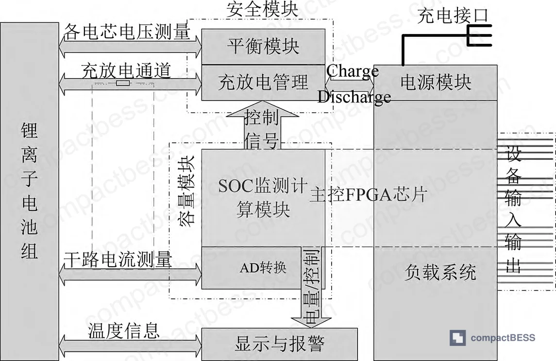
The model’s value isn’t just estimation accuracy — it’s the safety decisions that accurate state data enables. The source analysis categorizes five primary fault vectors for mobile LFP storage:
- Cell overcharge / overvoltage — leads to smoke, fire, electrolyte leakage
- Pack overcurrent — thermal runaway initiation pathway
- System overvoltage — high-voltage exposure, electric shock risk
- Insufficient charge input — inadequate output, system unavailability
- Low charge input — partial output degradation
BMS response to these faults depends entirely on how quickly and accurately the BMS knows the real SOC and internal resistance. A BMS running a simplified Coulomb-counting SOC with no resistance correction will misread remaining capacity by an increasing margin as the pack ages — triggering false over-discharge cutoffs or, worse, allowing genuine over-discharge because the SOC floor was calculated against a stale nominal capacity.
In supplier qualification, we evaluated BMS modules from six different suppliers against the DEKF co-estimation requirement. Three of the six could not provide any documentation showing whether their SOC algorithm updates internal resistance dynamically or uses a fixed lookup table. One supplier initially claimed “adaptive EKF” but on technical review, their implementation only updated the noise covariance matrix — not the resistance or capacity parameters. That’s not DEKF. That distinction matters when you’re specifying a pack for 5+ year field deployment.
The four BMS safety requirements that directly depend on accurate state estimation:
- Overcharge protection: requires accurate SOC to time charging cutoff
- Over-discharge protection: requires accurate capacity estimate to set floor
- Thermal runaway detection: requires resistance trend monitoring to catch early anomalies
- Predictive maintenance scheduling: requires SOH trajectory, not just point-in-time SOH
For detailed discussion of protection circuit dependencies, see Protection Circuit Design.
Compliance with IEC 62133 for portable sealed secondary lithium cells and IEC 62619 for stationary and mobile applications both require documented protection against overcharge, over-discharge, and overcurrent — but neither standard specifies which estimation algorithm a BMS must use to achieve those protections. That gap is where technically incompetent suppliers hide.
Buyers should also verify whether the BESS carries UN 38.3 transport certification for lithium battery shipments, particularly for cross-border logistics to North America and Europe. UL 9540 certification is increasingly demanded by North American integrators for containerized and mobile storage applications.
Practical Guidance for Buyers #
When you’re evaluating BMS suppliers for mobile BESS applications — whether it’s a 10 kWh portable unit or a 100 kWh grid-maintenance pack — the algorithm architecture is the specification item most buyers miss. Don’t just ask for SOC accuracy. Ask how that accuracy is maintained as the cell ages and internal resistance drifts.
The minimum viable DEKF implementation requires the BMS to co-estimate at least two parameters (internal resistance R₀ and capacity Cₚ) alongside the state vector. If a supplier’s technical documentation only describes a single Kalman filter loop or Coulomb counting with OCV correction, their SOC accuracy figures were measured on new cells and will degrade meaningfully in field conditions.
For mobile applications specifically — field service equipment, vehicle-mounted storage, portable power stations — the battery cannot be taken offline for calibration. The BMS must self-correct in real time. That requirement eliminates a significant portion of the BMS modules available in the lower price tiers.
At CompactBESS, our sourcing team works directly with verified manufacturers across China to help global OEM buyers and energy storage integrators evaluate BMS capability — including algorithm architecture — before committing to an RFQ. If you’re qualifying suppliers for a mobile BESS program that requires DEKF or equivalent co-estimation capability, we can help you identify and pre-screen candidates against your technical spec.
Need help identifying qualified suppliers for intelligent BMS with DEKF SOH estimation? Talk to our sourcing team →
Supplier Qualification Questions #
- Does your BMS implement joint state-and-parameter estimation — specifically, does the SOC filter update internal resistance (R₀) and capacity (Cₚ) dynamically, or are these fixed lookup values? Request documentation showing your EKF parameter vector θ = [R₀, Cₚ].
- What is your BMS’s SOC estimation error under charge conditions, measured at 0.3% or better, and under discharge conditions at 0.58% or better? Provide test results across at least three full charge/discharge cycles, not just a single-cycle snapshot.
- What end-of-life internal resistance threshold do you use to trigger SOH retirement? The model basis should define R_eol ≤ 1.6× nominal internal resistance — if your threshold is significantly higher, explain the chemistry and application justification.
- Can you provide simulation or validation data showing DEKF absolute deviation values per charge/discharge cycle, comparable to cycle-by-cycle deviation data (e.g., Cycle 1 charge deviation ≤ 0.0094, DEKF ≤ 0.0059)? Generic SOC accuracy claims without per-cycle data are not acceptable.
- For a 50 kWh-class mobile LFP pack, what is your BMS’s capacity estimation accuracy after three full cycles, and does your SOH calculation use capacity-fade method, resistance-change method, or both? If only one method is used, what is your technical justification for not implementing the dual-method approach?
Sourcing Checklist #
- [ ] BMS implements dual Extended Kalman Filter (DEKF) with separate fast-state (EKFₓ) and slow-parameter (EKFθ) loops — not single EKF or Coulomb counting only
- [ ] SOC estimation error documented at ≤ 0.3% on charge cycles and ≤ 0.58% on discharge cycles, verified across minimum 3 charge/discharge cycles
- [ ] Internal resistance (R₀) tracked dynamically; end-of-life threshold defined at ≤ 1.6× nominal internal resistance per SOH boundary formula
- [ ] SOH computation uses both capacity-based (Cᵢ/C₀) and resistance-based methods; resistance tracking confirms SOH ≥ 99.91% at nominal internal resistance levels
- [ ] BMS includes protection modules for all five fault vectors: cell overcharge, pack overcurrent, system overvoltage, and both under-charge states — with BMS response time documented
- [ ] Pack carries IEC 62619 certification (or equivalent national standard) for mobile secondary lithium battery safety
- [ ] UN 38.3 transport test certificate available for international shipment to buyer’s region
- [ ] Supplier can provide Matlab/Simulink or equivalent simulation validation data for BMS state estimation model, not just hardware test reports on new cells
Key Specifications Table #
| Parameter | Recommended Value | Verification Method |
|---|---|---|
| SOC estimation error (charge cycle) | ≤ 0.3% absolute deviation | Cycle-by-cycle simulation or hardware test log; minimum 3 cycles; compare EKF vs DEKF output |
| SOC estimation error (discharge cycle) | ≤ 0.58% absolute deviation | Hardware discharge test with reference coulometer; voltage error ≤ 1.05×10⁻⁴ V |
| Internal resistance (R₀) end-of-life threshold | ≤ 1.6× nominal Rₙ | Incremental discharge pulse test (HPPC) per IEC 62660-1; log R₀ per cycle |
| SOH (capacity-based) floor before intervention | ≥ 80% (Cᵢ/C₀) | EKF-based capacity estimation validated against reference Ah counter; confirmed at 1,400 Ah for 3 cycles in simulation |
| SOH (resistance-based) at nominal conditions | ≥ 99.91% at measured R₀ levels | Resistance-SOH formula: (Reol − Rᵦ)/(Reol − Rₙ); cross-check against capacity method |
| Battery voltage estimation error | ≤ 0.13% | Model voltage vs measured terminal voltage across full SOC range; 0–100% SOC sweep |
Can’t find a supplier meeting these specs? Submit your requirements and we’ll match you within 48 hours.
References #
Data source: State Estimation and Safety Monitoring for Mobile Lithium Energy Storage Systems Using Dual Extended Kalman Filtering, J. Liu et al., Journal of the Electrochemical Society, 2024
Frequently Asked Questions #
Q: What is the difference between EKF and DEKF in a BMS, and why does it matter for buyers?
A standard Extended Kalman Filter (EKF) estimates the battery’s state (SOC, RC voltages) using fixed model parameters — internal resistance and capacity are assumed to be constant or updated only occasionally. A Dual EKF (DEKF) runs two parallel filters simultaneously: one for the fast-changing state variables and one for the slowly evolving parameters (R₀ and Cₚ). Because resistance and capacity are co-estimated in real time, the SOC calculation uses accurate, current values rather than stale nominal values. In testing, this architecture reduced charge-cycle SOC deviation by up to 41% on Cycle 2 compared to single EKF. For buyers specifying a BMS that must maintain accuracy across a multi-year deployment without field recalibration, DEKF is the architecture to specify.
Q: What SOH threshold should I use as a battery replacement trigger in a mobile BESS application?
The internal resistance method provides earlier warning than capacity fade alone — resistance increases measurably before capacity drops become operationally significant. The end-of-life internal resistance threshold used in this analysis is 1.6× nominal R₀. For most LFP applications, capacity-based SOH below 80% is the conventional replacement trigger, but pairing it with a resistance threshold catches degradation earlier and prevents field failures.
Q: Can a standard BMS from a tier-2 Chinese supplier realistically implement DEKF?
Yes, but verify it. DEKF requires slightly more processing overhead than single EKF and demands proper initialization of the parameter covariance matrix. Many BMS firmware implementations claim “EKF-based SOC” but use fixed resistance lookup tables — effectively not DEKF. The test is simple: ask the supplier for per-cycle deviation data comparing their algorithm against single EKF. If they cannot produce it, the dual-filter architecture is probably not implemented.
Q: How does battery voltage error relate to SOC error in DEKF-based systems?
They are linked but not the same thing. In the simulation results, voltage estimation error was 0.13% on charge and 1.05×10⁻⁴ on discharge — both significantly lower than what single EKF achieves at the same conditions. Voltage error matters because the OCV-SOC lookup (the polynomial relationship used to convert voltage to SOC) amplifies any voltage error in the flat OCV region of LFP chemistry. Keeping voltage error below 0.2% is important for LFP specifically because its OCV plateau is unusually flat between 20–80% SOC.
Q: Is DEKF required for compliance with IEC 62619 or other battery safety standards?
No — IEC 62619 specifies protection outcomes (overcharge prevention, thermal cutoff, etc.) but does not mandate a specific estimation algorithm. However, achieving the protection outcomes reliably across the full service life of the battery increasingly depends on accurate real-time state estimation. A BMS with degraded SOC accuracy in aged cells may nominally comply with IEC 62619 on new-cell testing but fail to provide adequate protection two years into service.
Published by compactbess.com Technical Team | Request a sourcing quote


