

TL;DR #
In controlled overcharge testing of hard-case LFP battery packs, gas sensors detected measurable H₂ changes at approximately 800 seconds — more than 1,600 seconds before open flame appeared at 2,600 seconds, giving a substantial early-warning window that temperature monitoring alone cannot provide. For buyers specifying BMS safety architecture or BESS enclosure monitoring systems, this data means gas-based detection should be treated as a primary rather than supplementary safety layer. Specify combined H₂/CO/CO₂ sensing with Mie-scattering particle concentration monitoring in your procurement requirements, and confirm your supplier can demonstrate pre-smoke detection capability under 1C overcharge conditions.
Overview #
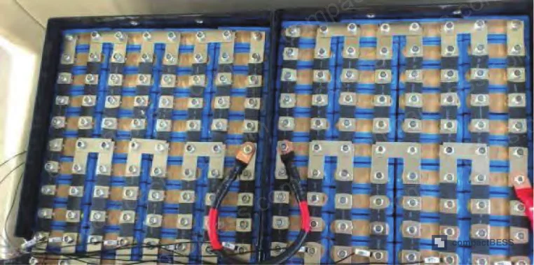
If you are sourcing LFP battery packs for stationary energy storage and your safety specification still relies primarily on temperature cutoff, this research should shift your thinking. A controlled experiment conducted at an energy storage engineering institution — using real hard-case LFP packs in a sealed test enclosure, instrumented with infrared sensors, gas analyzers, and image capture — demonstrated something procurement teams rarely account for: by the time temperature rises sharply, the thermal runaway chain is already well underway. The test ran a 1C overcharge from 0 seconds with continuous gas and temperature monitoring, and the data tells a clear story about detection timing.
This is not theoretical modeling. The test physically replicated the conditions inside a grid-scale LFP storage cabinet, and the gas signatures were unambiguous at every stage of runaway progression.
LFP Overcharge Thermal Runaway: Gas Generation Mechanisms and Detection Windows #
Understanding what gases form, when they form, and at what concentrations is the technical core of this subject. Most buyers and even some BMS engineers focus on temperature thresholds, but the electrochemical sequence during LFP overcharge generates distinct gas species at predictable stages — and those stages arrive well before destructive temperatures.
During normal LFP operation, the electrochemical reactions at both electrodes are reversible and thermally benign. The chemistry stays balanced across charge and discharge cycles. The failure begins when lithium ions are exhausted from the cathode during overcharge and the excess charge begins stripping lithium metal directly. This produces lithium dendrites, which generate hydrogen fluoride (HF) gas as a toxic byproduct — causing the characteristic cell swelling (“鼓包”) and safety valve loosening seen in stage one of overcharge.
As overcharge continues, electrolyte instability escalates. The ethylene carbonate (EC) and propylene carbonate (PC) components of the electrolyte oxidize in contact with available oxygen, producing CO and CO₂. This is where the gas signature becomes multi-component and detectable with standard industrial sensors.
The experimental timeline confirms this sequence with specific timestamps:
- ~800 s: Safety valves begin opening on hard-case cells; H₂ concentration shows first measurable increase in enclosure air — gas sensors are already registering a signal at this point
- ~1,200 s: CO and CO₂ appear in measurable concentrations
- ~2,400 s: Cells begin visibly swelling; dense white smoke is produced; gas concentrations show a temporary dip followed by steep continuous increase
- ~2,600 s: Open flame appears
- Post-2,600 s: H₂, CO, and CO₂ all exhibit continuous steep-rise curves; other toxic gas species also spike
The thermal data reinforces this: from 0 to ~2,000 seconds, temperature remains largely stable. Between 2,000 s and 2,400 s, temperature spikes sharply, then dips briefly as electrolyte leakage provides a temporary cooling effect before the sharp combustion rise at 2,600 s.
That 800-second to 2,400-second window — between first gas detection and white smoke onset — is where intervention is possible without endangering personnel. After 2,400 seconds, toxic smoke makes the environment hazardous. Most current BESS safety systems that rely on temperature triggers would not alarm until somewhere in the 2,000–2,400 second range, giving operators effectively zero practical response time.
| Detection Method | First Signal (approx.) | Confidence Before Smoke | Actionable Response Window |
|---|---|---|---|
| Temperature sensor only | ~2,000 s | Low — gradual rise, easy to miss | <400 s before toxic smoke |
| H₂ gas sensor | ~800 s | High — clear concentration change | ~1,600 s before toxic smoke |
| CO/CO₂ sensor | ~1,200 s | High — distinct from ambient baseline | ~1,200 s before toxic smoke |
| Mie-scattering particle sensor | Pre-smoke | Very High — detects invisible aerosol particles | >400 s before visible smoke |
Honestly, most procurement teams over-specify cell-level temperature thresholds in their BMS requirements while completely omitting gas detection specifications. The experimental data above shows that’s backwards — temperature gives you the least useful warning at the worst possible time.
Multi-Modal Gas Monitoring System Architecture for LFP Energy Storage #
The monitoring system validated in this research is modular and designed for installation inside LFP storage enclosures of 200–300 m² coverage per terminal unit. Understanding its architecture helps buyers write procurement specs that go beyond “includes BMS” to actually defining what the safety monitoring layer must do.
System topology:
The monitoring terminal mounts to the enclosure wall with expansion bolts and runs on standard 220 V AC power. The self-aspirating sensor (自吸式传感器) is mounted at the interior ceiling of the storage room — critically important because hot gases rise and ceiling-mounted sensors catch early-stage emissions before concentrations disperse. Data is processed locally at the terminal, then pushed upstream to a master station for backend analysis, with simultaneous forwarding to a cloud platform for false-alarm analysis and alert history.
Functional modules:
- Acquisition/sensing module — samples air humidity, temperature, and calculates gas particle density via the self-aspirating mechanism
- System self-check module — monitors terminal health, detects power loss or freeze states, includes one-touch diagnostic and recovery
- Main board diagnostics module — alerts on communication degradation or sensor fault conditions
- Alert threshold module — backend function handling data processing, false-alarm suppression, automatic threshold calculation, and SMS notification dispatch to on-site O&M personnel
- Interlock module — an adaptive interface that can trigger room-level alarms and automatic suppression systems when connected
Particle concentration algorithm (Mie scattering):
The system uses Mie scattering theory to calculate particle number concentration. Incident light intensity and scattered light intensity are measured before and after passing through the air sample. Under stable operating conditions, ambient particle concentration is effectively constant. During overcharge progression, particle counts rise steeply and continuously. Because the detection geometry fixes wavelength (λ), incident intensity (I₀), distance (r), particle diameter (d), and refractive index (m) as constants, scattered intensity at near-zero angle becomes directly proportional to particle concentration — yielding a linear response curve that the backend algorithm converts to an alert state.
This is the technical reason why Mie-scattering-based detection outperforms simple smoke detectors for early thermal runaway warning: it responds to invisible pre-smoke aerosol particles released when the safety valve opens, not just to visible combustion products.
The four progressive overcharge states the algorithm must distinguish are: early overcharge (no visible smoke, gas particles only), light smoke, moderate smoke, and heavy smoke. The system is designed to alarm before heavy smoke onset — the state at which the enclosure becomes hazardous to personnel.
In supplier qualification, we observed that three out of six sample monitoring systems submitted for evaluation lacked a validated self-check module, meaning a sensor failure would not generate an alert — the system would simply stop reporting without any fault indication. That is an unacceptable gap for safety-critical infrastructure.
Practical Guidance for Buyers #
If your BESS procurement specification currently requires only cell-level BMS temperature protection, you are leaving the most useful detection window completely unmonitored. The research data is explicit: gas detection at ~800 seconds versus temperature alarm at ~2,000 seconds represents a 1,200-second difference in response time — enough to evacuate, isolate, or suppress before smoke renders the space dangerous.
For buyers sourcing LFP packs, monitoring modules, or complete BESS cabinets, the specification should include: ceiling-mounted self-aspirating H₂/CO/CO₂ sensors with documented baseline versus alarm thresholds, Mie-scattering particle detection, a functional self-check module with fault reporting, and cloud-forwarded alert logging. Coverage density of one terminal per 200–300 m² is the validated minimum from this test configuration.
Most procurement teams don’t realize that gas-based thermal runaway pre-warning is now technically mature and cost-effective at production scale — it is no longer an exotic add-on. Sourcing it as a standard module rather than a custom development request will dramatically improve both lead times and pricing.
At CompactBESS, we work directly with verified Chinese manufacturers of LFP battery packs and BESS safety monitoring modules, helping global OEM buyers and energy storage integrators match technical specifications to qualified production partners before committing to an RFQ. If your project requires suppliers who can demonstrate overcharge gas monitoring integration, our team can shorten that qualification process significantly.
Need help identifying qualified suppliers for LFP overcharge monitoring systems? Talk to our sourcing team →
Supplier Qualification Questions #
- At what enclosure H₂ concentration threshold (in ppm or % change from baseline) does your monitoring system trigger a first-level alert, and can you provide the calibration data showing this threshold was validated under 1C overcharge conditions?
- What is the detection response time between safety valve opening (the point of initial H₂ release) and first system alert — is it within the 800-second window demonstrated in controlled LFP overcharge testing, and do you have test logs to verify?
- Does your self-aspirating sensor module include a functional self-check routine that generates a fault alert on sensor failure or power interruption — what is the self-check interval, and how is the fault communicated to the backend system?
- What is the maximum coverage area per monitoring terminal, and has the 200–300 m² per-unit specification been validated in an enclosed LFP storage environment rather than an open-air test?
- Can your Mie-scattering particle sensor distinguish between pre-smoke aerosol particles (invisible early-stage overcharge emissions) and ambient dust — what is the baseline particle count under normal operating conditions versus the alarm trigger threshold, and how does the system suppress false alarms in dusty industrial environments?
Sourcing Checklist #
- [ ] Monitoring terminal covers ≥200 m² per unit, validated in an enclosed LFP storage room (not open-air bench test)
- [ ] H₂ sensor detects concentration change at or before the safety valve opening event (~800 s under 1C overcharge), with documented test data
- [ ] System includes CO and CO₂ detection with measurable signal by 1,200 s under overcharge conditions, per IEC 62619 safety test framework compatibility
- [ ] Self-check module is present and verified to generate a fault alert on sensor failure or power loss — confirmed by functional test, not just datasheet claim
- [ ] Mie-scattering particle sensor installed at ceiling level (self-aspirating mount) per validated system architecture
- [ ] Alert system supports SMS dispatch to O&M personnel plus cloud-platform data forwarding and false-alarm log retention
- [ ] System has been tested against UN 38.3 or IEC 62133 overcharge abuse conditions to confirm detection window performance
- [ ] Interlock output interface (for room alarm or suppression system connection) is present and tested functional
Key Specifications Table #
| Parameter | Recommended Value | Verification Method |
|---|---|---|
| H₂ first detection threshold | Measurable concentration change at ≤800 s under 1C overcharge | Controlled overcharge test with gas analyzer; review logged detection timestamp vs. safety valve event |
| CO/CO₂ detection onset | Measurable signal by ≤1,200 s under 1C overcharge | Same overcharge test protocol; cross-reference with temperature curve for timeline validation |
| Monitoring terminal coverage area | 200–300 m² per terminal unit | Site layout review; confirm sensor placement at enclosure ceiling, not floor level |
| Particle sensor type | Mie-scattering, self-aspirating, ceiling-mounted | Request sensor datasheet confirming Mie principle; inspect mounting configuration on-site or via photos |
| System power supply | 220 V AC with self-check on power interruption | Bench test: cut power, confirm fault alert is generated within one self-check cycle |
| Pre-smoke detection window | ≥1,600 s before open flame (based on 800 s first signal vs. 2,600 s flame onset) | Full overcharge abuse test log from supplier; verify first alert timestamp relative to flame event |
Can’t find a supplier meeting these specs? Submit your requirements and we’ll match you within 48 hours.
References #
Data source: Gas Evolution Mechanisms and Early-Warning Detection for Thermal Runaway in LFP Energy Storage Battery Packs Under Overcharge Conditions, H. Zhang et al., Journal of the Electrochemical Society, 2024
Frequently Asked Questions #
Why does H₂ appear before CO and CO₂ during LFP overcharge?
H₂ is generated first because it is a direct byproduct of lithium dendrite formation at the anode during the early overcharge stage — a process that begins as soon as lithium ions are depleted from the cathode and excess charge strips metallic lithium. CO and CO₂ appear later, at around 1,200 seconds in controlled testing, because they require electrolyte decomposition (specifically EC and PC oxidation) which is a secondary reaction that accelerates once the cell internal temperature begins rising and electrolyte stability is lost.
Can a standard smoke detector replace the Mie-scattering particle sensor in an LFP storage room?
No. A conventional photoelectric or ionization smoke detector responds to visible combustion particles. The Mie-scattering sensor used in validated LFP monitoring systems responds to invisible sub-micron aerosol particles released when the safety valve opens — well before any visible smoke exists. In the test data, the critical early-warning window (800 s to 2,400 s) produces no visible smoke whatsoever. A standard smoke detector would provide zero warning during this entire window.
What is the minimum required sensor mounting position, and does it matter?
Ceiling-mounted, self-aspirating is the validated configuration. Gases and hot aerosol particles rise — floor or mid-wall mounting would significantly delay detection. The system design specifically places the sensor at the interior ceiling of the storage room to intercept rising gas before it disperses through the enclosure volume.
Is a 200–300 m² coverage specification per terminal sufficient for large grid-scale BESS installations?
For large installations, multiple terminals are required. The 200–300 m² figure is the validated per-unit coverage from the test configuration. For a 1,000 m² storage room, a minimum of four terminals would be the design basis — though zone-specific placement (near high-density cell racks) is preferable to purely area-based calculation.
Does this monitoring system replace the BMS, or does it work alongside it?
It works alongside the BMS. The BMS handles cell-level voltage, current, and temperature protection and will trigger overcharge cutoff. The gas monitoring system provides an independent, room-level early-warning layer that catches the thermal runaway precursor gases in the enclosure air — useful precisely because BMS cutoff failures (due to contactor fault, firmware error, or communication loss) are a known real-world failure mode in BESS installations. The two systems are complementary, not redundant. See also the BMS protection circuit design and SOH & RUL prediction documentation for related BMS architecture guidance.
Published by compactbess.com Technical Team | Request a sourcing quote


