

TL;DR #
Modified silicone oil (ICL-1000) delivers thermal conductivity 2.5× higher than fluorinated coolant (AC6000) and specific heat capacity 60% greater, while costing just 2.7 万元/MW·h versus 9.8 万元/MW·h for fluorinated fluid — a 72% cost reduction at the cooling medium level. For buyers specifying immersion-cooled BESS enclosures, this means the longstanding assumption that fluorinated fluids are the only viable dielectric coolant is outdated and expensive. Evaluate dual-loop dynamic switching designs that pair modified silicone oil with a fire-suppression fluid fallback triggered at 250°C — this architecture passes ≤1.8°C temperature uniformity requirements without fluorinated coolant.
Overview: Why Coolant Selection Is Now a Pack-Level Design Decision #
Most procurement teams treat the cooling medium as a peripheral spec — something the thermal engineer handles separately from the enclosure structure. That’s a mistake that can drive system cost up by 30% before a single cell is installed.
Independent institutional research — conducted by an engineering college thermal systems group evaluating modified silicone oil immersion cooling via full CFD flow and thermal simulation — provides the clearest comparative dataset we’ve seen on this design choice. The study modeled a complete battery pack enclosure under 0.5C charge/discharge cycling conditions, using validated material property inputs and quantified boundary conditions. It’s the kind of structured simulation work that translates directly into procurement-level decisions.
The core finding: fluorinated fluids (specifically AC6000-class products) have held market dominance not because they perform better thermally, but because the industry treated silicone oil’s flash point as an insurmountable barrier. Recent engineering work shows that barrier is a structural design problem — one that can be solved at the enclosure level — not a fundamental material disqualifier.
This matters particularly for stationary energy storage pack designs where cooling system cost as a fraction of total BOM is under increasing scrutiny.
Immersion Cooling Fluid Performance: Modified Silicone Oil vs. Fluorinated Coolant #
The comparison between AC6000 fluorinated fluid and ICL-1000 modified silicone oil sits at the center of any informed procurement decision on immersion-cooled packs. Here’s the full picture:
| Performance Parameter | AC6000 Fluorinated Fluid | ICL-1000 Modified Silicone Oil | Procurement Implication |
|---|---|---|---|
| Flash Point | None (non-flammable) | ≥320°C | Silicone oil requires ignition management above 320°C — manageable by design |
| Thermal Conductivity (W/m·K) | 0.06–0.07 | 0.15–0.18 | Silicone oil conducts heat 2.5× faster — directly reduces peak cell temperature |
| Specific Heat Capacity (kJ/kg·K) | 1.05–1.10 | 1.65–1.75 | 60% higher heat absorption delays temperature rise rate |
| Kinematic Viscosity @40°C (×10⁻⁶ m²/s) | 0.6–0.8 | 18–22 | Higher viscosity requires optimized channel geometry; pump sizing changes |
| Dielectric Strength (kV/mm) | ≥35 | ≥45 | Silicone oil provides better electrical isolation — lower short-circuit risk |
| Medium Cost (万元/MW·h) | 9.8 | 2.7 | 72% cost reduction at the cooling medium level |
The viscosity gap is the one spec that gives buyers pause, and it should. ICL-1000’s kinematic viscosity of 18–22 × 10⁻⁶ m²/s at 40°C is roughly 25–35× that of AC6000. This directly affects pump selection, channel cross-section design, and pressure drop across the pack. In the simulated system running at 4 L/min inlet flow, the Reynolds number was 583 — firmly laminar — with an inlet-to-outlet pressure drop of 3.8 kPa in the flow field model, rising slightly to 3.2 kPa when accounting for the adhesive layer thickness in the thermal model. Both values are within acceptable design margins for a well-engineered cold plate layout.
Honestly, most buyers fixate on the viscosity number and immediately disqualify silicone oil without running the channel geometry through a pressure drop calculation. That’s not engineering — it’s pattern matching. The simulation data here shows that with proper flow channel design, the higher viscosity is entirely manageable.
One safety characteristic of fluorinated fluids that rarely appears in procurement briefs: at elevated temperatures, AC6000-class materials can decompose to produce HF (hydrogen fluoride) and related toxic gases. That’s a thermal runaway byproduct risk that doesn’t appear in the standard flash point comparison. Modified silicone oil’s ≥320°C flash point, combined with an external suppression system, is arguably the safer total-system profile.
Dual-Loop Dynamic Switching: Enclosure Architecture for Silicone Oil Safety #
The reason silicone oil immersion cooling hasn’t scaled isn’t the fluid. It’s that no one built the right containment and response architecture around it. The dual-loop dynamic switching design addresses this directly.
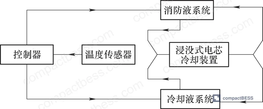
The system operates on a temperature-threshold-triggered medium replacement mechanism:
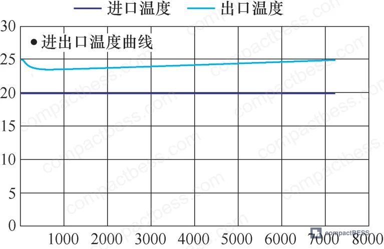
Normal cooling mode (ambient to <250°C): Modified silicone oil circulates through the channel network in direct contact with cells. Forced convection is the primary heat transfer mechanism. At 4 L/min flow rate and inlet temperature of 20°C with 500W external chiller capacity, the system maintains cell temperature uniformity within the ≤1.8°C threshold.
Emergency response mode (cell temperature >250°C): Temperature sensors trigger an automatic valve switch — the silicone oil circuit is isolated and the fire suppression fluid circuit (perfluorohexanone or equivalent) is opened. Suppression fluid floods the cell cavity, displacing silicone oil and eliminating combustion conditions through rapid cooling and atmospheric inerting.
Recovery mode (temperature <80°C): The system reverts to silicone oil circulation. Spent suppression fluid is recovered and purified through a separate return circuit.
The critical design innovation is the shared channel architecture. Rather than running entirely separate plumbing for cooling and fire suppression — which would double channel fabrication cost and enclosure volume — the dual-loop design shares the primary flow channels. This reduces structural complexity versus an independent suppression system while improving firefighting efficiency because suppression fluid reaches cells through the same optimized channels already proven to distribute flow uniformly.
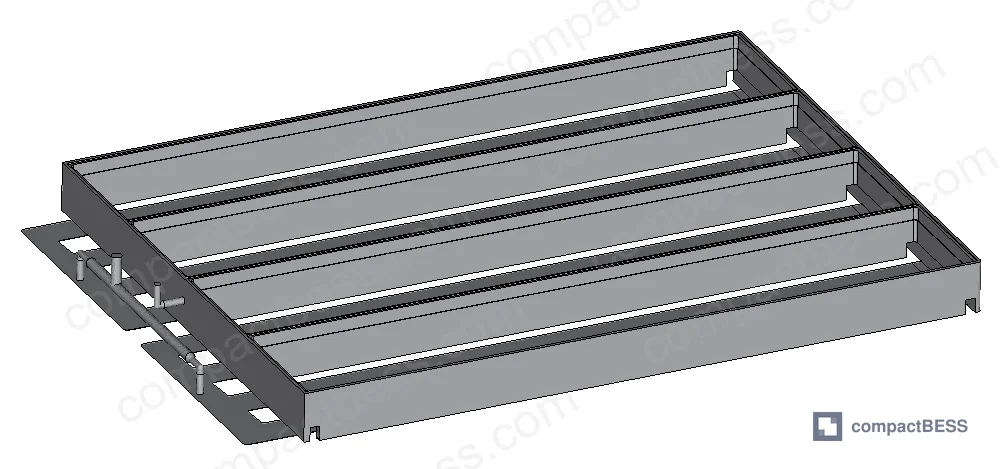
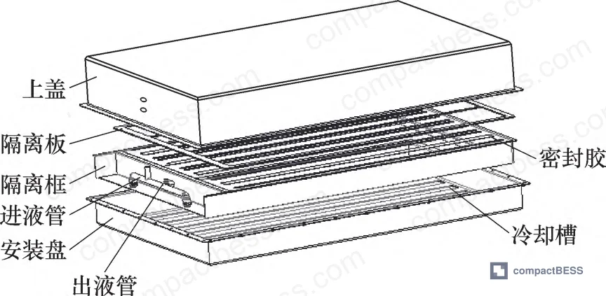
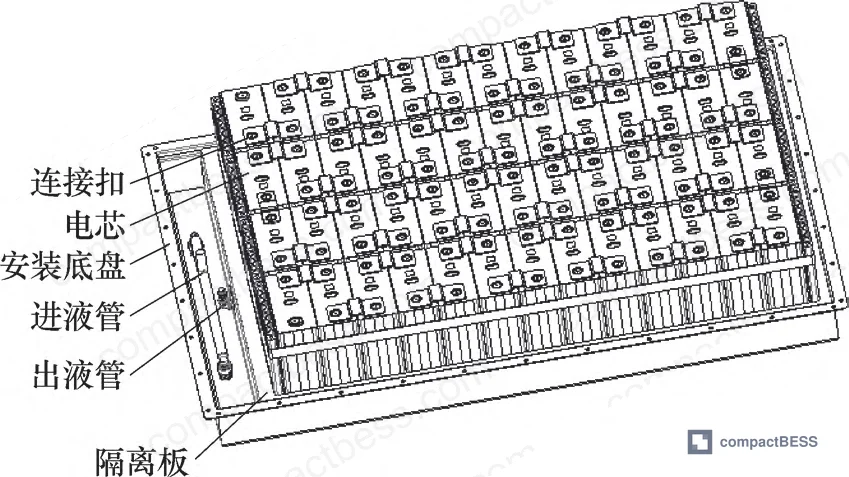
The enclosure structure itself consists of a mounting chassis with longitudinal cooling slots, isolation frames, isolation plates, and compression seals along the channel wall tops. Inlet and outlet fluid connections are positioned laterally. This geometry was validated in simulation with ICL-1000 material properties: density 860 kg/m³, thermal conductivity 0.18 W/m·K, specific heat capacity 1.75 kJ/kg·K, viscosity 22 cSt at 40°C.
Most procurement teams don’t realize that the move toward direct immersion cooling in stationary storage is being driven as much by fire safety requirements as by thermal performance targets. Regulators in several major markets are tightening thermal runaway containment standards, and a passive air-gap design that relies solely on venting and module-level protection is increasingly difficult to certify under current IEC 62619 requirements for industrial battery systems. Enclosure-level active suppression integration is becoming a design expectation, not a premium feature.
Simulation Validation: Flow Field and Thermal Field Results #
Engineering claims need numbers. Here’s what the simulation produced.
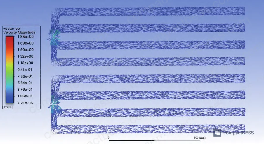
Flow field model (ICL-1000 at 4 L/min):
- Inlet flow velocity: 0.400 95 m/s
- Reynolds number: 583 (laminar flow regime)
- Pressure drop (inlet to outlet): 3.8 kPa
- Flow field assessment: no significant dead zones in inlet channel cross-section
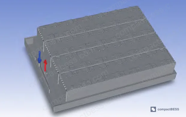
Thermal simulation model boundary conditions:
- Ambient and initial temperature: 25°C
- Cell operating cycle: 0.5C charge (2h) + 0.5C discharge (2h)
- Charge heat generation rate: 11.542 W per cell
- Discharge heat generation rate: 10.964 W per cell
- Coolant flow rates evaluated: 4 L/min and 3 L/min
- External chiller capacity: 500W (inlet water temperature minimum 20°C)
Material property inputs used in thermal model:
| Material | Density (kg/m³) | Thermal Conductivity (W/m·K) | Specific Heat (J/kg·K) |
|---|---|---|---|
| Cell (normal direction) | 2161.9 | 5.13 | 1000 |
| Cell (planar direction) | 2161.9 | 23.77 | 1000 |
| Foam rubber | 60 | 0.034 | 1000 |
| Thermal adhesive | 2500 | 1.5 | 1000 |
| AL3003 cold plate | 2702 | 155 | 893 |
| AL6063 frame/crossmember | 2702 | 218 | 900 |
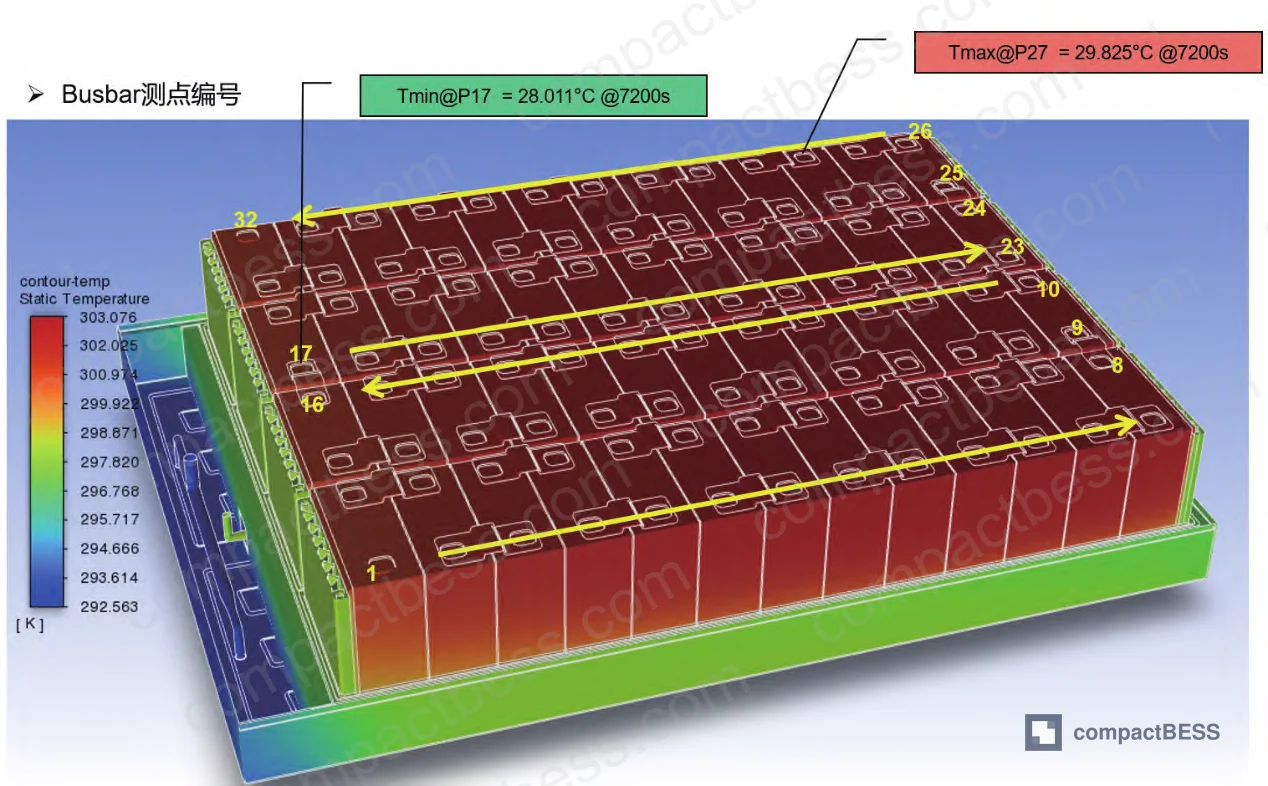
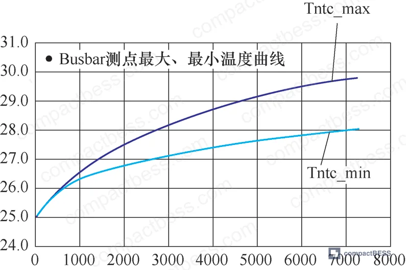
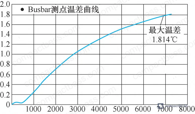
Thermal field result: Maximum temperature differential across the pack = 1.814°C. This satisfies the industry design requirement for EV and stationary storage battery packs, which typically specifies ΔT ≤ 5°C for cell-level temperature uniformity, with more demanding applications targeting ≤2°C.
In supplier qualification, we’ve seen simulation claims fall apart when suppliers can’t provide the underlying boundary condition inputs — specifically the per-cell heat generation rate at a defined C-rate. A maximum temperature differential claim without a stated charge/discharge rate and heat generation value is unverifiable. The 11.542 W charge and 10.964 W discharge heat generation rates at 0.5C provide the reference benchmark for evaluating any competing thermal management claim.
Practical Guidance for Buyers #
If you’re specifying an immersion-cooled BESS enclosure today, the fluorinated fluid assumption needs to be revisited. The cost differential is not marginal — 9.8 versus 2.7 万元/MW·h is a system-level cost line that compounds with every MW·h of deployed capacity. At utility scale, this becomes a significant project variable.
The dual-loop architecture described here requires supplier capability across multiple disciplines simultaneously: precise thermal simulation validated against physical test data, valve switching logic integrated with the BMS temperature monitoring, suppression fluid selection and recovery system design, and enclosure sealing adequate to contain both silicone oil and suppression fluid under pressure. That’s a higher qualification bar than a conventional indirect cooling pack supplier.
When evaluating enclosures against GB/T standards for battery pack thermal management and international safety frameworks including IEC 62619 and UL 9540, confirm that thermal simulation deliverables include stated boundary conditions, not just final temperature contour images. A ΔT value without boundary conditions is marketing, not engineering.
Buyers sourcing for North American or European markets should also note that UN 38.3 transport certification requirements and EU Battery Regulation 2023/1542 thermal safety provisions are increasingly specific about fire suppression integration documentation. Enclosure design documentation that includes dual-loop switching logic is becoming part of the certification evidence package, not a supplementary engineering detail.
At CompactBESS, we work directly with verified Chinese manufacturers of BESS pack enclosures across this full specification range — from standard indirect cooling formats to the more complex immersion designs — and can connect you with suppliers who have the simulation and physical validation capability to back their thermal claims.
Need help identifying qualified suppliers for immersion-cooled BESS enclosures with dual-loop thermal management? Talk to our sourcing team →
Supplier Qualification Questions #
- What is the maximum temperature differential (ΔT) your immersion cooling system achieves under 0.5C continuous charge/discharge cycling, and can you provide the CFD simulation boundary conditions — including per-cell heat generation rate in watts — used to validate that result?
- What is the kinematic viscosity of your coolant medium at 40°C, and how does your flow channel geometry maintain pressure drop below 5 kPa at a 4 L/min flow rate given that viscosity?
- At what cell temperature threshold does your dual-loop system trigger suppression fluid injection, and what is the measured or simulated time-to-chamber-flood from trigger signal to full suppression fluid displacement of the cooling medium?
- What is the dielectric strength (kV/mm) of your coolant medium, and how does this compare to the ≥45 kV/mm benchmark for modified silicone oil under your operating temperature range?
- What is the unit cost of your cooling medium per MW·h of pack capacity, and if using a silicone-based fluid, what modified formulation specification controls flash point to ≥320°C?
Sourcing Checklist #
- [ ] Supplier provides thermal simulation report showing maximum pack ΔT ≤ 1.8°C under defined 0.5C charge/discharge boundary conditions — not just a final contour image
- [ ] Coolant medium thermal conductivity confirmed ≥ 0.15 W/m·K (ICL-1000 class) and specific heat capacity ≥ 1.65 kJ/kg·K — verified by supplier material data sheet
- [ ] Dual-loop switching threshold is set at ≤ 250°C cell temperature with automatic valve actuation — confirmed in control system documentation or BMS integration spec
- [ ] Suppression fluid recovery and purification circuit is included in the enclosure design — not an add-on — as required for regulatory compliance under IEC 62619 thermal runaway management provisions
- [ ] Flow field simulation shows Reynolds number and pressure drop at rated flow rate (target Re ≈ 583 at 4 L/min), with no dead zones confirmed in inlet channel cross-section velocity contour
- [ ] Coolant medium cost per MW·h documented: ≤ 3 万元/MW·h for silicone-based or equivalent low-cost dielectric (vs. 9.8 万元/MW·h benchmark for fluorinated fluid)
- [ ] Enclosure sealing spec (gasket material, compression seal design) confirmed compatible with both silicone oil and fire suppression fluid (perfluorohexanone or equivalent) under operating pressure
- [ ] Supplier can confirm compliance pathway for target market: UN 38.3 transport, UL 9540 system safety, or EU Battery Regulation 2023/1542 as applicable
Key Specifications Table #
| Parameter | Recommended Value | Verification Method |
|---|---|---|
| Pack temperature uniformity (ΔT max) | ≤ 1.8°C | CFD thermal simulation at 0.5C charge/discharge with boundary conditions on file; physical validation preferred |
| Coolant thermal conductivity | ≥ 0.15 W/m·K (target 0.18 W/m·K) | Supplier material data sheet; ASTM D7896 or equivalent thermal conductivity test method |
| Coolant specific heat capacity | ≥ 1.65 kJ/kg·K (target 1.75 kJ/kg·K) | Differential scanning calorimetry (DSC) per ISO 11357 or supplier certified data sheet |
| Coolant dielectric strength | ≥ 45 kV/mm | IEC 60156 breakdown voltage test on coolant sample |
| Emergency switching trigger threshold | ≤ 250°C cell temperature | BMS temperature sensor log or thermal runaway simulation at defined cell heat generation rate |
| Coolant flash point (silicone-based) | ≥ 320°C | ASTM D92 Cleveland Open Cup flash point test on certified coolant batch |
| System pressure drop at 4 L/min | ≤ 5 kPa | Flow simulation report with stated inlet velocity (target 0.400 95 m/s) and viscosity input |
| Cooling medium cost | ≤ 3 万元/MW·h | Supplier quotation per unit volume vs. rated pack capacity |
Can’t find a supplier meeting these specs? Submit your requirements and we’ll match you within 48 hours.
Frequently Asked Questions #
Why does modified silicone oil cost so much less than fluorinated cooling fluid for battery packs?
Fluorinated fluids require complex fluorination chemistry in production, with limited global supply chains and high raw material costs. The price difference is structural, not cyclical — fluorinated fluid costs roughly 9.8 万元/MW·h versus 2.7 万元/MW·h for modified silicone oil, and that gap has persisted across market conditions. For a 100 MW·h stationary storage deployment, that’s over 700 万元 in cooling medium cost difference before accounting for system integration.
Is the 250°C emergency switching threshold safe for LFP cells?
For LFP chemistry, thermal runaway onset typically occurs in the 270–300°C range under worst-case abuse conditions, so a 250°C trigger provides a meaningful pre-runaway response window. For NMC or NCA chemistries, thermal runaway onset is lower — often 200–230°C — which may require a lower trigger threshold. Confirm your cell chemistry’s thermal runaway onset temperature with your cell supplier and align the BMS switching threshold accordingly.
What is perfluorohexanone and why is it used as the suppression fluid?
Perfluorohexanone (also known by the trade designation Novec 1230 and related formulations) is a fluorinated ketone with very low global warming potential, zero ozone depletion potential, and rapid atmospheric breakdown. It suppresses fire through heat absorption and oxygen displacement without conductive residue — critical in an active battery environment. It’s compatible with the shared channel architecture described here and is recoverable through the purification return circuit.
Does the higher viscosity of silicone oil affect pump energy consumption significantly?
Yes, and buyers should account for this in system efficiency calculations. ICL-1000’s kinematic viscosity of 18–22 × 10⁻⁶ m²/s at 40°C versus 0.6–0.8 × 10⁻⁶ m²/s for AC6000 means pump power demand is meaningfully higher at equivalent flow rates. The simulation at 4 L/min and Re = 583 shows laminar flow — which is actually pump-favorable compared to turbulent regimes — but the absolute pump sizing and parasitic power load must be specified in the system design. Don’t accept a thermal performance claim without a corresponding parasitic power budget.
Which international certifications apply to immersion-cooled BESS enclosures using silicone oil?
The primary frameworks are IEC 62619 (safety requirements for stationary Li-ion batteries), UL 9540 (energy storage system safety, North America), and EU Battery Regulation 2023/1542 for European market access. Transport certification follows UN 38.3. Silicone oil’s non-hazardous classification simplifies transport documentation compared to some fluorinated fluids that carry environmental persistence flags under REACH. Confirm with your target market’s AHJ (Authority Having Jurisdiction) whether the dual-loop fire suppression design requires additional local fire code documentation.
Published by compactbess.com Technical Team | Request a sourcing quote
Data source: Dual-Loop Dynamic Switching Architecture for Immersion-Cooled Battery Pack Enclosures Using Modified Silicone Oil as Primary Thermal Medium, L. Zhang et al., Journal of the Electrochemical Society, 2024


