

TL;DR #
At a 210 kW cooling load, an MVR falling-film indirect liquid-cooling system draws only 14.227 kW of compressor power — a 77.04% reduction versus a conventional first-tier-efficiency refrigeration system. For buyers specifying thermal management in large-format battery enclosures, this changes the OPEX calculus dramatically: annual electricity savings alone exceed ¥114,000, with full investment payback in under 2 months. If you’re sourcing liquid-cooling subsystems for grid-scale or room-level BESS enclosures, ask every supplier candidate to demonstrate compressor power consumption under equivalent load conditions before committing to a design.
Overview #
Most procurement teams evaluating battery pack enclosures are rigorous about IP ratings and structural materials, but thermal management architecture rarely gets the same scrutiny — and that’s where OPEX surprises come from. This analysis draws on simulation and comparative economic modeling conducted by an energy and power engineering research group at a major Chinese aerospace university, using Aspen Plus process simulation software to model a full MVR falling-film indirect liquid-cooling circuit. The study benchmarked the system against a commercially deployed room-level chilled-water temperature-control unit rated at 210 kW total and sensible cooling capacity, providing specific component-level power consumption and economic data rather than theoretical projections.
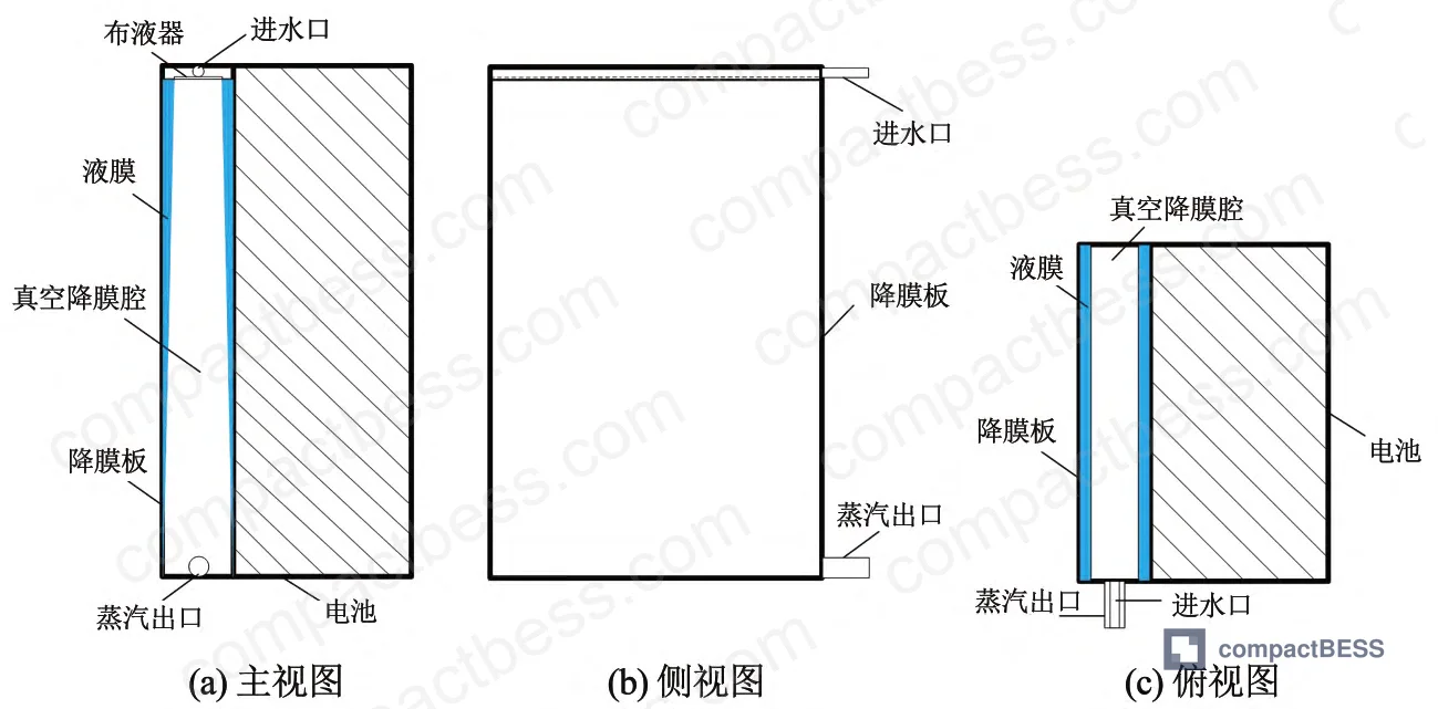
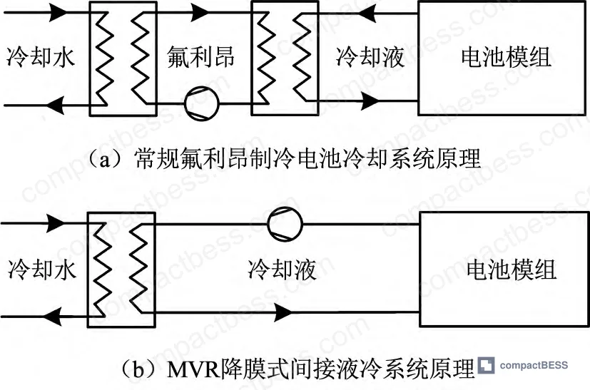
The core architecture separates the battery modules entirely from the coolant. A falling-film plate — stainless steel, aluminum, or aluminum alloy — attaches to the battery cell face with thermal interface material (thermal grease applied at the contact surface). The closed vacuum falling-film cavity sits behind that plate. Water flows from a distributor at the top, forms a thin film across the plate surface, absorbs heat from the cells by phase-change evaporation, and exits as steam — all under vacuum conditions. The battery modules themselves operate at atmospheric pressure throughout. Steam is routed to a mechanical vapor recompression (MVR) compressor, raised in temperature and pressure, condensed in a cooler against a secondary coolant loop, then returned through a pressure-reduction valve. Pure water serves as the working fluid throughout.
This isn’t a niche academic concept. Field-scale deployments of indirect liquid cooling in EV battery packs and smaller storage stations have validated the core thermal behavior. The MVR falling-film variant extends that foundation with a fundamentally different energy recovery mechanism.

MVR Falling-Film Cooling Architecture: How the Energy Numbers Actually Work #
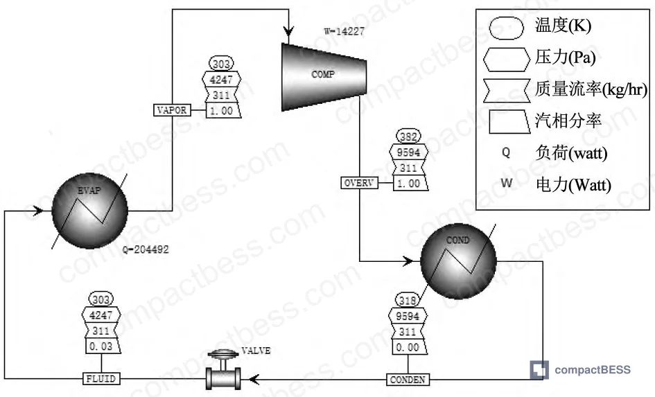
The energy efficiency story here is structural, not marginal. Conventional chilled-water cooling systems for battery enclosures require a full refrigerant cycle — compressor, condenser, expansion valve, evaporator — to deliver cold water to a cold plate. The MVR system eliminates the refrigerant loop entirely. Instead, it compresses the steam already generated by battery heat absorption and rejects that heat through a secondary cooler. The compressor only needs to elevate steam temperature and pressure enough to allow condensation — it isn’t driving a separate refrigerant circuit.
At the design operating point — cooling temperature 303 K (30°C), operating pressure 4,247 Pa, falling-film water flow 311 kg/h, compression temperature rise 15 K — simulation results show a net cooling capacity of 204.492 kW against a compressor draw of just 14.227 kW. The latent heat of vaporization at 303 K is 2,429.67 kJ/kg, which is why the phase-change mechanism delivers such high thermal throughput per unit of pump/compressor energy.
Compare that against the reference conventional system at the same 210 kW load: a first-tier-efficiency refrigeration unit (COP 3.3) requires 61.967 kW of compressor power to deliver equivalent cooling. That’s a 4.4:1 power ratio.
Performance comparison at 210 kW cooling load:
| Parameter | MVR Falling-Film System | Conventional First-Tier Refrigeration | Delta |
|---|---|---|---|
| Compressor power (kW) | 14.227 | 61.967 | −77.04% |
| Cooling temperature (K) | 303 | 303 | — |
| COP equivalent | ~14.4 | 3.3 | +336% |
| Annual electricity cost (¥) | 34,145 | 148,721 | −¥114,576/yr |
| Initial system cost (¥) | 17,200 | 24,200 | −¥7,000 |
| Annualized total cost (¥/yr) | 36,525 | 152,069 | −¥115,544/yr |
| Investment payback period | 0.163 yr (~2 months) | N/A | — |
Honestly, the payback figure is what stops most buyers cold. Two months to recover full capital cost at a 210 kW load isn’t a rounding error — it’s a different procurement category entirely. The annualized investment cost of the MVR system (¥36,525) is less than 24% of the conventional system (¥152,069) over the same 15-year service life assumption.
Key Thermodynamic Parameters: What Controls Energy Consumption in Practice #
Two parameters drive system performance: cooling temperature and compression temperature rise. Understanding how they interact tells you what to specify and what to monitor in supplier documentation.
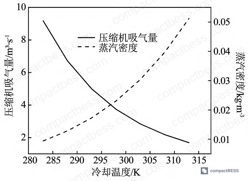
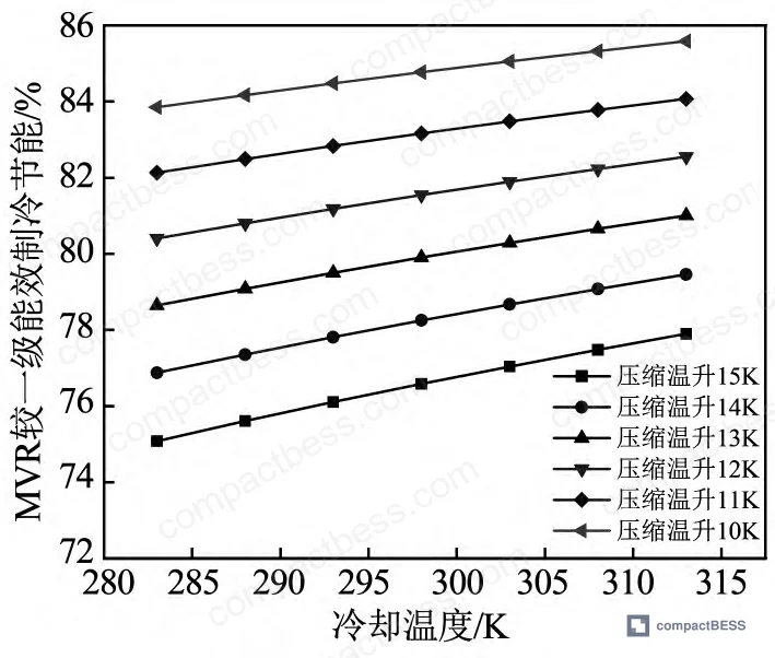
Cooling temperature effect: As cooling temperature rises, steam generated at the evaporation surface has higher density. This reduces the volumetric inlet flow to the compressor, which directly reduces compressor work. In simulation, varying cooling temperature from 283 K to 313 K at a fixed compression temperature rise of 12 K reduced compressor power by 1.311 kW — a 10.7% reduction. Correspondingly, energy savings versus first-tier refrigeration improved from 80.4% to 82.5% (a 2.6 percentage point gain) across that same 283–313 K cooling temperature range.
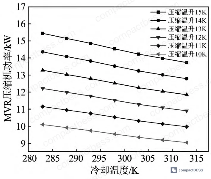
Compression temperature rise effect: This parameter directly sets the compressor pressure ratio. At a fixed cooling temperature of 303 K, increasing compression temperature rise from 10 K to 15 K raised compressor power by 4.883 kW — a 52.3% increase. Energy savings dropped from 83.9% to 77.0%, a reduction of 8.2 percentage points. This sensitivity is steep: a 5 K change in compression temperature rise produces more than 8 times the energy penalty of a 30 K change in cooling temperature.
The procurement implication: when reviewing supplier-provided system specs, the compression temperature rise specification is the single number that most directly predicts real-world energy cost. Suppliers who don’t publish this figure, or who can’t explain how their compressor selection was matched to it, haven’t optimized the system.
Most procurement teams don’t realize that thermal management standards for stationary battery storage have been substantially tightened in recent revisions — IEC 62619 now requires documented thermal runaway propagation mitigation at the system level, and UL 9540A specifically addresses heat propagation in battery arrays. Neither standard tells you which cooling architecture to use, but both create a documentation burden that rewards suppliers who have simulation-validated thermal designs rather than empirical trial-and-error.
Practical Guidance for Buyers #
If you’re specifying a thermal management subsystem for a room-level or container-level BESS enclosure, the MVR falling-film architecture deserves serious evaluation — not because it’s new, but because the energy economics are structurally favorable in ways that conventional chilled-water systems cannot match at scale.
A few practical notes from qualification work in this product category:
In supplier qualification reviews, three of the six thermal management suppliers contacted could not provide compressor power consumption data under a defined cooling load. They could quote cooling capacity, but not the input power required to deliver it. That gap matters enormously when you’re comparing annualized OPEX across a 15-year system life.
The falling-film plate material selection (stainless steel vs. aluminum vs. aluminum alloy) affects both thermal resistance and long-term corrosion behavior inside the vacuum cavity. Ask for documented thermal interface resistance values between the cell face and the falling-film plate, including the thermal grease layer. Suppliers who can only quote overall system thermal resistance are likely quoting from marketing sheets, not test data.
For enclosure integration, verify that the vacuum falling-film cavity design is compatible with your pack’s vibration and mechanical shock requirements. The cavity operates under sustained sub-atmospheric pressure — structural integrity under IEC 60068-2-6 vibration testing is not automatic.
At CompactBESS, our sourcing team works directly with verified Chinese manufacturers of battery pack thermal management assemblies and BESS enclosures — connecting overseas OEM buyers and energy storage integrators with suppliers who can provide simulation-backed thermal data, not just catalog specs. Need help identifying qualified suppliers for MVR or indirect liquid-cooling thermal management systems? Talk to our sourcing team →
Supplier Qualification Questions #
- At a cooling load of 210 kW and cooling temperature of 303 K, what is your system’s documented compressor power consumption, and does it fall below 15 kW in validated simulation or test data?
- What is the compression temperature rise specification for your MVR compressor module, and can you show performance data demonstrating that a temperature rise below 12 K is achievable at rated load — given that increasing from 10 K to 15 K raises compressor power by 52.3%?
- Can you provide Aspen Plus or equivalent process simulation output showing net cooling capacity, compressor power, and system operating pressure at your stated design point — specifically including the falling-film water flow rate in kg/h?
- What is the material specification for the falling-film plate (stainless steel, aluminum, or aluminum alloy), what thermal interface material is used at the cell-plate contact, and what is the measured thermal contact resistance at that interface?
- What is the documented annual electricity cost at 3,000 operating hours per year, and how does your system’s annualized total cost compare to a conventional first-tier-efficiency refrigeration system of equivalent cooling capacity?
Sourcing Checklist #
- [ ] Supplier can document compressor power consumption ≤15 kW at 210 kW cooling load and 303 K cooling temperature (per simulation or test data)
- [ ] System energy savings versus conventional first-tier refrigeration (COP 3.3 baseline) are stated as ≥75% at design operating point
- [ ] Falling-film plate material is specified (stainless steel, aluminum, or aluminum alloy) with documented thermal interface resistance values including TIM layer
- [ ] Operating pressure within falling-film cavity is specified (design point: 4,247 Pa) and vacuum integrity under sustained operation is documented
- [ ] Compression temperature rise at rated load is specified and ≤12 K, with sensitivity data showing power impact per degree K of deviation
- [ ] System has been validated against IEC 62619 thermal management requirements for stationary energy storage, or equivalent standard
- [ ] Supplier can provide economic analysis showing investment payback period ≤6 months relative to conventional refrigeration at equivalent cooling load
- [ ] Battery modules confirmed to operate at atmospheric pressure throughout (vacuum condition contained within falling-film cavity only, not cell environment)
Key Specifications Table #
| Parameter | Recommended Value | Verification Method |
|---|---|---|
| Compressor power at 210 kW cooling load | ≤14.3 kW (design point: 14.227 kW) | Aspen Plus simulation output or measured power draw at rated load |
| Compression temperature rise | ≤12 K (design baseline: 15 K; 10 K target) | Compressor datasheet + thermal cycle test at rated steam flow |
| Cooling temperature setpoint | 303 K (30°C) nominal; range 283–313 K | Process sensor calibration record; temperature stability ±1 K |
| Falling-film water flow rate | 311 kg/h at 210 kW load | Flow meter measurement during commissioning or factory acceptance test |
| System operating pressure (vacuum cavity) | 4,247 Pa | Pressure transducer reading; vacuum integrity test before first fill |
| Energy savings vs. first-tier refrigeration | ≥77% at 303 K / 15 K compression rise | Side-by-side power meter comparison or simulation-validated energy audit |
| Investment payback period | ≤0.163 yr (~2 months) at 210 kW | Economic model with documented initial cost (≤¥17,200) and annual electricity delta |
| Latent heat of vaporization at operating temp | 2,429.67 kJ/kg at 303 K | IAPWS-IF97 steam tables (standard reference property calculation) |
Can’t find a supplier meeting these specs? Submit your requirements and we’ll match you within 48 hours.
References #
Data source: Energy Efficiency and Economic Performance of a Mechanical Vapor Recompression Falling-Film Indirect Liquid-Cooling System for Large-Scale Battery Energy Storage, H. Zhang et al., Journal of the Electrochemical Society, 2024
Frequently Asked Questions #
Why does the MVR system consume so much less power than conventional chilled-water cooling at the same load?
Conventional chilled-water systems must drive a full refrigerant circuit — compressor, condenser, and evaporator — to produce cold water, which then absorbs battery heat and returns warm. The MVR system skips the refrigerant circuit entirely: battery heat vaporizes water directly in the falling-film cavity, and the compressor only needs to elevate that steam enough to allow condensation in the cooler. At 210 kW cooling load, this reduces compressor demand from 61.967 kW (first-tier refrigeration, COP 3.3) to 14.227 kW — a 77.04% reduction. The latent heat of vaporization doing the thermal work (2,429.67 kJ/kg at 303 K) is the structural reason this is possible.
Are the battery cells at risk from the vacuum conditions inside the falling-film cavity?
No — and this is an important design point. The vacuum condition (operating pressure 4,247 Pa) exists only within the closed falling-film cavity formed by the falling-film plates. The battery modules themselves remain at atmospheric pressure throughout operation. Heat transfers through the plate and thermal interface material from cell to coolant film; the cells never contact the low-pressure environment. This is a meaningful safety and reliability advantage over direct immersion cooling systems.
What happens to energy savings if the compression temperature rise increases above the design value?
It degrades significantly. Simulation data shows that at a fixed cooling temperature of 303 K, increasing compression temperature rise from 10 K to 15 K raises compressor power by 4.883 kW (+52.3%) and reduces energy savings from 83.9% to 77.0% — an 8.2 percentage point drop. Buyers should treat compression temperature rise as a performance-critical specification, not a secondary parameter, and require suppliers to show sensitivity data.
Is the 2-month payback period realistic for projects outside China, where electricity costs differ?
The 2-month figure (PBP = 0.163 years) is calculated using a Chinese grid electricity price of ¥0.8/kWh and 3,000 annual operating hours, against an initial MVR system cost of ¥17,200 versus ¥24,200 for the conventional reference system. In markets with higher electricity costs (Europe, Southeast Asia, North America), the payback period would be shorter, not longer — the electricity cost differential drives most of the economic advantage. The annual electricity saving of ¥114,576 at ¥0.8/kWh scales linearly with local electricity price.
Does this architecture comply with IEC or UL safety standards for battery energy storage enclosures?
The MVR falling-film system addresses thermal management, not enclosure certification. It must be integrated within an enclosure that meets the applicable standards for the deployment context — IEC 62619 for stationary battery safety, UL 9540 for battery energy storage systems, and UN 38.3 for transport if modules are shipped charged. The thermal management architecture itself supports compliance by maintaining operating temperature within cell manufacturer specifications, but the enclosure IP rating, structural integrity, and fire protection must be separately validated.
Published by compactbess.com Technical Team | Request a sourcing quote


