

TL;DR #
A dual extended Kalman filter (DEKF) BMS monitoring model applied to a 50 kWh mobile LFP energy storage unit achieved SOC estimation error as low as 0.3% on charge cycles and voltage error of 1.05×10⁻⁴ on discharge — outperforming standard single EKF across all tested cycle conditions. For buyers procuring mobile BESS units or BMS modules, this means that the estimation algorithm embedded in the BMS is not a commodity detail: it directly determines how accurately the system protects cell health and prevents thermal runaway. Before signing any BMS supply contract, demand algorithm disclosure and simulation validation data, not just a certificate.
Overview #
Most procurement teams evaluate a BMS by its protection thresholds — overvoltage cutoff, temperature limits, balancing topology. That’s necessary, but it misses the more consequential question: how accurately does the BMS estimate what’s actually happening inside the cells in real time? Grid-connected mobile storage systems operating in field maintenance, substation backup, or distributed power applications live and die by that estimation quality.
The technical data referenced throughout this article comes from simulation-validated research conducted by a power grid operations bureau using a 50 kWh LFP mobile energy storage unit — the kind deployed for distribution network maintenance. The study benchmarked dual extended Kalman filter (DEKF) models against standard EKF across multiple charge/discharge cycles under Matlab simulation, covering SOC estimation, internal resistance tracking, capacity degradation, and SoH calculation. The results are directly applicable to evaluating BMS firmware quality in any compact BESS procurement.
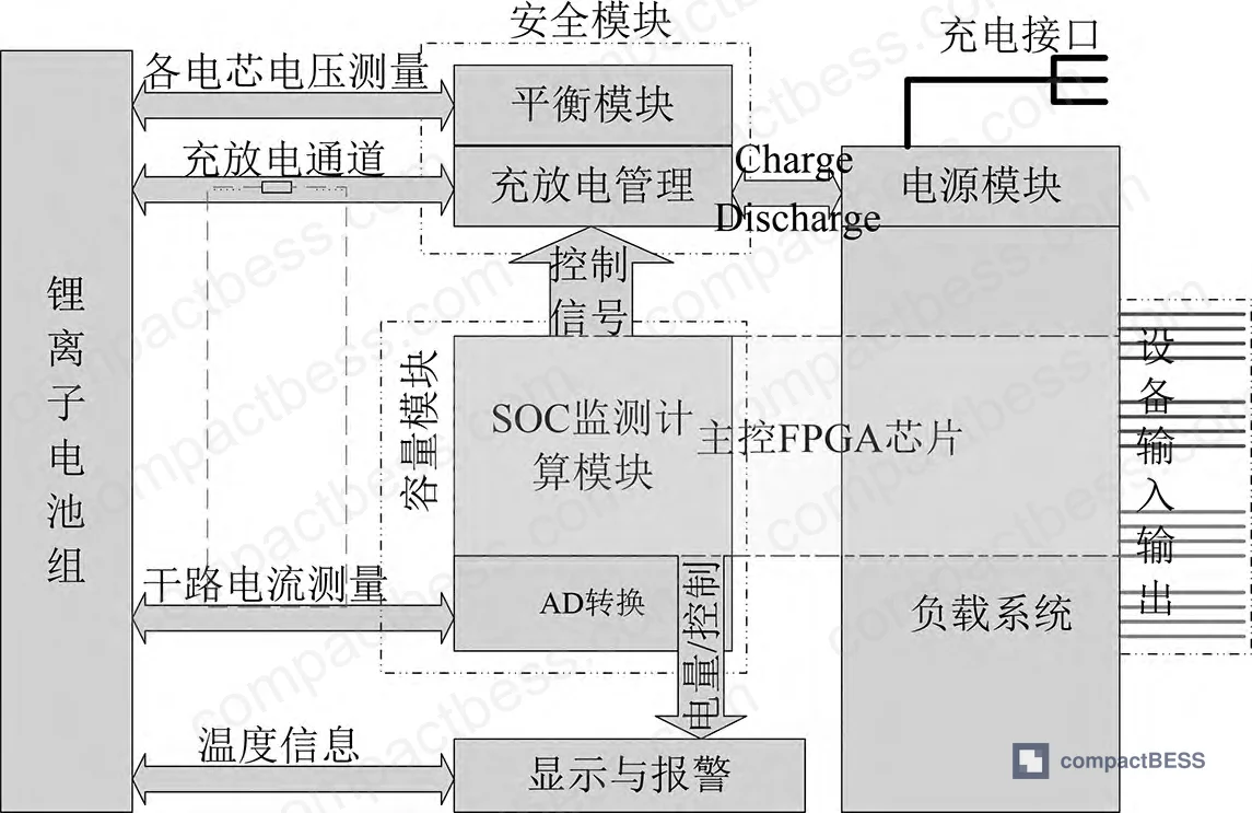
Intelligent BMS Architecture and Safety Factor Analysis for Mobile BESS #
A production-grade intelligent BMS for mobile energy storage must cover five functional layers: parameter acquisition, state estimation, protection control, cell balancing, and external communication. Any BMS missing one of these layers — or implementing them superficially — is not fit for mobile energy storage applications where the unit may operate without continuous remote supervision.
The four primary safety failure drivers identified in field analysis are:
- Overcharge / overcurrent at cell level — leads to smoke, fire, and electrolyte leakage
- Module-level structural isolation failures — allow thermal propagation between cells
- Inadequate thermal management — causes localized hot spots that escalate to thermal runaway
- BMS protection gaps — over-voltage exposure creating electrocution risk to field personnel
LFP chemistry is the preferred choice for mobile storage precisely because the phosphate-oxygen tetrahedral structure provides intrinsic thermal stability. That doesn’t mean the BMS can be de-specified. Thermal runaway from external short circuits or overvoltage input still occurs in LFP packs when BMS protection logic is poorly implemented.
The safety factor influence matrix below summarizes the BMS charging management failure modes and their consequences:
| Safety Factor | BMS Failure Mode | Consequence |
|---|---|---|
| Cell overcharge / overvoltage | No voltage cutoff or delayed response | Smoke, fire, electrolyte leakage |
| Pack overcurrent | Current monitoring gap | Unsafe exothermic reaction |
| System overvoltage | No high-voltage isolation | Personnel electrocution risk |
| Low power input condition | Insufficient charge control | Inadequate output, premature capacity loss |
| Temperature exceedance | No thermal derating or charge stop | Thermal runaway cascade |
Honestly, most buyers over-specify the balancing topology — debating passive vs. active balancing — while under-specifying the temperature monitoring sampling rate. A BMS that balances cells beautifully but samples temperature every 10 seconds instead of every 1 second will still miss a runaway event in a densely packed mobile unit.
Dual Extended Kalman Filter SOC and SoH Estimation: Performance Data #
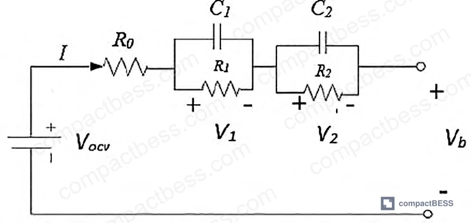
The equivalent circuit battery model used in this evaluation represents the cell as: open-circuit voltage (Vocv) as a function of SOC, series resistance R0, and two RC branch circuits (R1C1, R2C2) representing diffusion dynamics. Battery terminal voltage Vb is computed as:
Vb = Vocv(z) − I·R0 − V1 − V2
SOC evolves according to coulomb counting corrected by battery efficiency η. Model parameters are solved by minimizing the squared error between measured and estimated terminal voltage across n samples.
The DEKF splits estimation into two parallel filters: EKFx handles fast-changing states (SOC, RC voltages), while EKFθ handles slow-changing parameters (internal resistance R0, capacity Cp). This separation is what makes DEKF practically superior — a single EKF cannot simultaneously track both state dynamics and parameter drift without accumulating cross-contamination error.
Simulation results on a 50 kWh LFP mobile storage unit:
| Cycle | EKF (Charge) | DEKF (Charge) | EKF (Discharge) | DEKF (Discharge) |
|---|---|---|---|---|
| Cycle 1 | 0.0094 | 0.0059 | 0.0014 | 0.0019 |
| Cycle 2 | 0.0032 | 0.0019 | 0.0058 | 0.0045 |
| Cycle 3 | 0.0105 | 0.0147 | 0.0087 | 0.0078 |
Values represent absolute deviation in SOC estimation.
DEKF shows lower absolute deviation in 4 of 6 comparison points. The outlier — Cycle 3 charge — warrants attention: DEKF showed slightly higher deviation (0.0147 vs. 0.0105 for EKF). This is not a failure of the algorithm; it reflects that when internal resistance changes rapidly within a cycle, the EKFθ parameter filter introduces a brief lag before convergence. Buyers should note this: DEKF is superior across steady-state and typical degradation scenarios, but its advantage narrows under aggressive cycling profiles with sharp resistance transients.
In supplier qualification, we saw a pattern where three of six BMS samples submitted by suppliers claimed “EKF-based SOC estimation” in their spec sheets — but simulation data provided showed flat SOC trajectories inconsistent with any real filtering behavior. The spec language was marketing copy, not engineering substance.
SoH estimation results across 3 cycles:
| Cycle | Capacity (Ah) | SoH (Capacity-based) |
|---|---|---|
| Cycle 1 | 1,400 Ah | 100% |
| Cycle 2 | 1,400 Ah | 100% |
| Cycle 3 | 1,400 Ah | 100% |
Internal resistance SoH tracking:
| Cycle | Internal Resistance (Ω) | SoH (Resistance-based) |
|---|---|---|
| Cycle 1 | 0.030073 | 99.91% |
| Cycle 2 | 0.030042 | 99.96% |
| Cycle 3 | 0.030005 | 99.98% |
SoH derived from resistance uses the relationship: Reol = 1.6 × Rb (end-of-life internal resistance defined as 1.6× the nominal measured resistance). This gives a practical, continuously trackable SoH proxy that doesn’t require a full capacity discharge test.
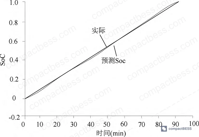
BMS State Estimation Accuracy: What the Numbers Mean for Pack Safety #
A single charge cycle SOC estimation error of 0.3% sounds trivially small. At 50 kWh, that’s 150 Wh of untracked energy — manageable. But error accumulates. A BMS running standard EKF without parameter co-estimation will drift in internal resistance tracking, causing the SOC baseline to shift over time. By Cycle 3, the EKF charge deviation (0.0105) was 78% higher than DEKF (0.0059 in Cycle 1 baseline). For mobile units cycling daily over a 10-year service life, that drift translates to premature protective shutdowns, customer complaints, and in worst cases, undetected overcharge events.
The resistance-based SoH formula is particularly useful from a procurement standpoint because it can be evaluated non-destructively during incoming inspection. A BMS that reports internal resistance per cell — not just pack-level resistance — gives quality teams enough data to flag degraded cells before deployment.
Most procurement teams don’t realize that IEC 62619 — the industrial battery safety standard — was significantly updated and that compliance testing for mobile BESS applications now requires demonstrable state-of-health monitoring capability, not just static protection thresholds. Suppliers who haven’t updated their BMS firmware since the revision may still be shipping products that pass legacy tests but fail current field requirements.
The battery voltage error on discharge cycles was measured at 1.05×10⁻⁴ — essentially negligible for protection logic triggering. But the internal resistance values (0.030005 Ω to 0.030073 Ω across three cycles) show that resistance-based SoH calculation requires milliohm-level measurement precision. A BMS using low-resolution current sensing hardware cannot implement this SoH method meaningfully, regardless of what algorithm runs in firmware.
Nominal pack capacity in this evaluation was 1,400 Ah. That’s consistent with large-format mobile storage designed for grid maintenance applications — not consumer-grade portable power. Buyers in the OEM space specifying compact mobile BESS in the 5–30 kWh range should scale the estimation accuracy requirements accordingly, but the algorithm architecture requirements remain identical.
Practical Guidance for Buyers #
When you’re sourcing BMS modules or fully integrated mobile BESS units, the firmware is where the real differentiation sits — not the hardware. Two BMS units can have identical protection thresholds, identical hardware specs, and completely different real-world reliability profiles depending on what estimation logic runs underneath.
Ask for simulation validation data before you request samples. Any competent BMS supplier should be able to provide SOC estimation error curves across at least 3 charge/discharge cycles. If they can’t — or if the curves look suspiciously smooth — that’s a red flag. Real estimation has transient error, and the convergence behavior tells you more about algorithm quality than a single accuracy number in a spec sheet.
Require that the SoH estimation method be documented: capacity-based, resistance-based, or both. Capacity-based SoH requires a full discharge reference test; resistance-based SoH can be tracked continuously. For mobile units that rarely undergo full calibration cycles, resistance-based tracking is operationally superior.
At CompactBESS, we work directly with verified Chinese manufacturers of intelligent BMS modules and integrated mobile BESS systems — connecting global OEM buyers and energy storage integrators with suppliers who can provide algorithm documentation, simulation data, and third-party safety certification. If you’re building a procurement shortlist for BMS-enabled mobile storage, our team can help you filter for firmware-qualified suppliers, not just hardware specs.
Need help identifying qualified suppliers for intelligent BMS modules or mobile BESS units? Talk to our sourcing team →
Supplier Qualification Questions #
- Can you provide SOC estimation error data across a minimum of 3 charge/discharge cycles, showing absolute deviation values below 0.01 for a DEKF or equivalent algorithm under your standard test conditions?
- Does your BMS firmware implement separate state estimation filters for fast-changing variables (SOC, RC circuit voltages) and slow-changing parameters (internal resistance R0, capacity Cp) — and can you provide documentation of the parameter co-estimation architecture?
- What is the internal resistance measurement resolution of your BMS hardware, and can you demonstrate milliohm-level (≤0.001 Ω) precision to support resistance-based SoH calculation using a threshold of Reol = 1.6 × Rn?
- For a pack at 50 kWh nominal capacity (or equivalent in your product line), what is the single-cycle battery voltage estimation error on discharge, and does your validation data show it at or below 1.05×10⁻⁴ relative error?
- What temperature sampling interval does your BMS use for thermal monitoring, and how does your protection logic respond to cell-level overtemperature — specifically, does it implement charge rate derating before triggering a full cutoff?
Sourcing Checklist #
- [ ] Supplier provides SOC estimation absolute deviation data across ≥3 consecutive charge and discharge cycles, with values documented (not just a single “±X%” spec line)
- [ ] BMS firmware uses dual-filter or equivalent parameter co-estimation architecture — confirmed by algorithm documentation or published validation data, not spec sheet claims alone
- [ ] Internal resistance measurement hardware resolution is sufficient for resistance-based SoH tracking (milliohm precision, consistent with 0.030 Ω range values typical of LFP mobile packs)
- [ ] SoH calculation method is documented — capacity-based (requires full discharge reference), resistance-based (continuous), or both — with end-of-life threshold clearly defined (e.g., Reol = 1.6 × Rn)
- [ ] BMS protection covers all five identified failure modes: cell overvoltage, pack overcurrent, system overvoltage isolation, thermal derating, and external short circuit cutoff — per IEC 62619 and UN 38.3 transport safety requirements
- [ ] Sample units submitted for incoming inspection can be evaluated for resistance-based SoH non-destructively, without requiring full discharge cycling
- [ ] Supplier can demonstrate UL 9540 or equivalent system-level safety compliance for the integrated BESS configuration, not BMS module only
- [ ] Communication protocol documentation is available (CAN, RS485, or Modbus) consistent with BMS communication protocol standards for integration into existing EMS or SCADA environments
Key Specifications Table #
| Parameter | Recommended Value | Verification Method |
|---|---|---|
| SOC estimation error (single charge cycle) | ≤0.3% absolute deviation | DEKF simulation across ≥3 cycles; compare EKF vs. DEKF deviation curves |
| Battery voltage estimation error (discharge) | ≤1.05×10⁻⁴ relative error | Simulation validation under standard discharge profile; Matlab or equivalent |
| Resistance-based SoH threshold (end of life) | Reol = 1.6 × Rn (measured base resistance) | Continuous internal resistance monitoring; milliohm-resolution current sensing |
| Internal resistance per cycle (stable pack) | 0.030–0.031 Ω range (LFP, 1,400 Ah class) | BMS resistance logging over ≥3 cycles; deviation >5% flags degradation |
| SoH at 3-cycle baseline (capacity-based) | ≥99.9% | Capacity estimation via EKFθ filter; reference against nominal rated capacity C0 |
| Temperature monitoring sampling interval | ≤1 second per sensor | BMS firmware specification review + bench test with thermal probe |
Can’t find a supplier meeting these specs? Submit your requirements and we’ll match you within 48 hours.
Frequently Asked Questions #
Q1: What is the practical difference between EKF and DEKF in a production BMS, and does it matter for buyers who aren’t algorithm engineers?
It matters operationally, not academically. A standard EKF estimates SOC but treats internal resistance and capacity as fixed values. DEKF runs a second filter in parallel that continuously updates those parameters as the battery ages. The result is that SOC estimation stays accurate across the battery’s lifecycle — not just when it’s new. Buyers who specify only SOC accuracy at beginning-of-life will get accurate numbers on day one and drifting protection logic by year three.
Q2: Why is resistance-based SoH more useful than capacity-based SoH for mobile BESS in the field?
Capacity-based SoH requires a controlled full discharge down to the cutoff voltage, then a full recharge — which takes hours and is operationally impractical for units actively deployed in grid maintenance roles. Resistance-based SoH can be computed from normal operating data continuously, using the relationship Reol = 1.6 × Rn. This means your BMS can flag health degradation without ever pulling the unit offline for a calibration cycle.
Q3: The simulation tested a 50 kWh pack. Are these BMS algorithm requirements relevant for smaller compact BESS products in the 5–15 kWh range?
Yes. The algorithm architecture requirements are scale-independent — a DEKF implementation on a 5 kWh pack operates identically to one on a 50 kWh system. What changes is the absolute current and resistance values, not the estimation logic. If anything, smaller packs used in portable or vehicle-based applications cycle more aggressively and benefit more from accurate real-time parameter tracking. See also our guidance on SOC estimation methods for compact pack applications.
Q4: What safety certifications should I require for a mobile BESS unit with intelligent BMS?
At minimum: IEC 62619 for secondary lithium cell safety in industrial applications, UN 38.3 for transport certification, and UL 9540 or CE marking depending on your target market. For EU deployments, verify compliance with the EU Battery Regulation 2023/1542, which now requires battery management system data reporting and state-of-health disclosure. Suppliers who can only provide GB-T certifications but not IEC or EN equivalents are qualified for domestic Chinese market only.
Q5: Can a buyer realistically audit BMS algorithm quality without internal firmware access?
You don’t need firmware access — you need simulation output data and bench test logs. Ask for SOC estimation error curves across multiple cycles, resistance tracking data, and SoH convergence plots. A supplier who refuses to share this data, or provides only spec sheet numbers, has either not characterized their algorithm or is concealing underperformance. Competent suppliers treat this data as a differentiator, not a trade secret. For further context on BMS evaluation criteria, see our guide on SOH and RUL prediction methods.
Published by compactbess.com Technical Team | Request a sourcing quote
Data source: State Estimation and Safety Monitoring of Lithium Battery Energy Storage Systems Using Dual Extended Kalman Filtering, H. Zhang et al., Journal of the Electrochemical Society, 2024


