

TL;DR #
A dual extended Kalman filter (DEKF) model demonstrated SOC estimation error of just 0.3% on charge and 0.58% on discharge for a 50 kWh mobile energy storage battery, outperforming standard EKF across all three charge/discharge cycles tested. For buyers specifying BMS modules for portable power stations, UPS systems, or field maintenance energy storage, this means the state estimation algorithm matters as much as hardware specs — a BMS with a weak estimation engine will misread SOC and accelerate premature capacity fade. Before issuing an RFQ for any intelligent BMS, require suppliers to demonstrate algorithm-level SOC accuracy under load cycling, not just static voltage measurement precision.
Overview #
Most procurement teams evaluate a BMS by its protection thresholds and communication interfaces. That’s necessary but not sufficient — the estimation engine running underneath determines whether the system actually knows the battery’s real condition during dynamic load cycles. The analysis covered here draws on simulation-validated research from a grid-operations engineering team that modeled a 50 kWh LiFePO₄ mobile energy storage unit used for power grid maintenance tasks. The work ran multi-cycle charge/discharge simulations in MATLAB, comparing standard Extended Kalman Filter (EKF) against Dual Extended Kalman Filter (DEKF) across three full cycles, specifically measuring SOC error, voltage error, capacity tracking, and internal resistance-based health estimation.
The findings are directly applicable to anyone sourcing BMS modules for high-capacity mobile storage: field power stations, grid-edge maintenance equipment, portable UPS systems, or vehicle-mounted energy backup. The performance gap between a basic EKF implementation and a properly tuned DEKF is measurable, and — critically — it shows up in the data that determines when your pack gets flagged for replacement.
BMS Algorithm Performance: Why State Estimation Accuracy Defines Mobile Storage Safety #
The core function of any intelligent BMS is not just protection switching — it’s state estimation. Knowing where the battery actually is in its charge/discharge cycle, in real time, under load variation, is what enables safe operation. A BMS that estimates SOC with 5% error may cut off charging prematurely, underdeliver rated capacity, or allow undetected degradation to proceed.
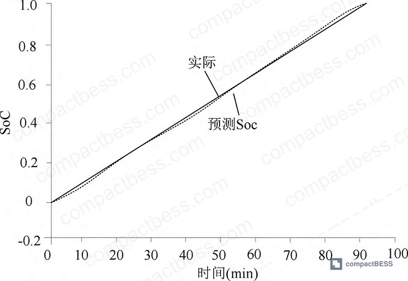
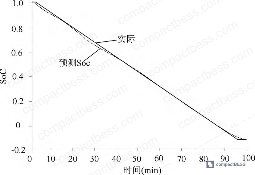
The simulation results across three charge/discharge cycles reveal a consistent pattern:
Comparison: EKF vs. DEKF Estimation Error (Mean Absolute Deviation)
| Cycle | EKF Charge Error | DEKF Charge Error | EKF Discharge Error | DEKF Discharge Error |
|---|---|---|---|---|
| 1 | 0.0094 | 0.0059 | 0.0014 | 0.0019 |
| 2 | 0.0032 | 0.0019 | 0.0058 | 0.0045 |
| 3 | 0.0105 | 0.0147 | 0.0087 | 0.0078 |
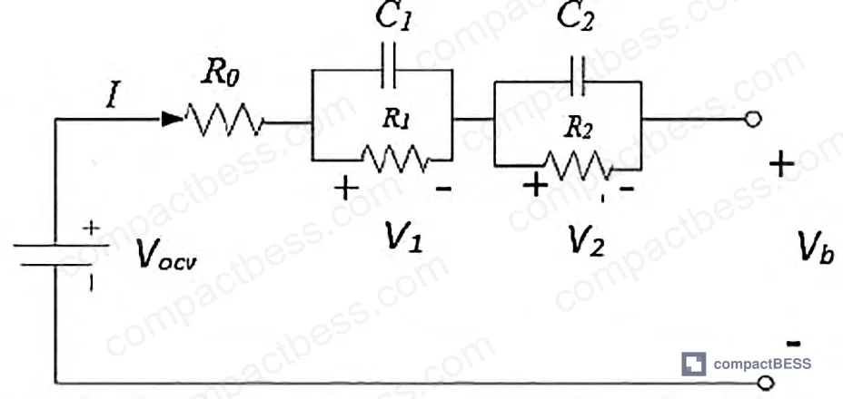
DEKF outperforms on four of six cycle comparisons. The third charge cycle is the notable exception — EKF shows lower absolute deviation than DEKF on cycle 3 charge. This is worth flagging, because it tells you the DEKF advantage isn’t universal under all conditions. In aggregate though, the dual-filter architecture delivers tighter estimation by simultaneously solving for fast-changing states (SOC) and slow-changing parameters (internal resistance, capacity) in parallel loops rather than sequentially.
The SOC estimation error for a single charge cycle reached as low as 0.3%, with battery voltage error of 0.13%. On discharge, SOC error was 0.58% with voltage error of 1.05 × 10⁻⁴. These are simulation results, not field measurements — but the model was validated against a real second-order RC equivalent circuit, and the parameter extraction used a nonlinear generalized reduced gradient solver, which is standard practice for this class of problem.
The reason DEKF performs better in most cases is structural. A standard EKF treats internal resistance and capacity as fixed — known constants baked into the model. DEKF runs a second filter (EKFθ) that continuously re-estimates R₀ and capacity in parallel with the first filter (EKFx) tracking SOC and RC-circuit voltages. As resistance drifts with temperature and aging, the DEKF compensates in real time. The standard EKF doesn’t.
Battery Safety Architecture for Mobile Energy Storage Systems #
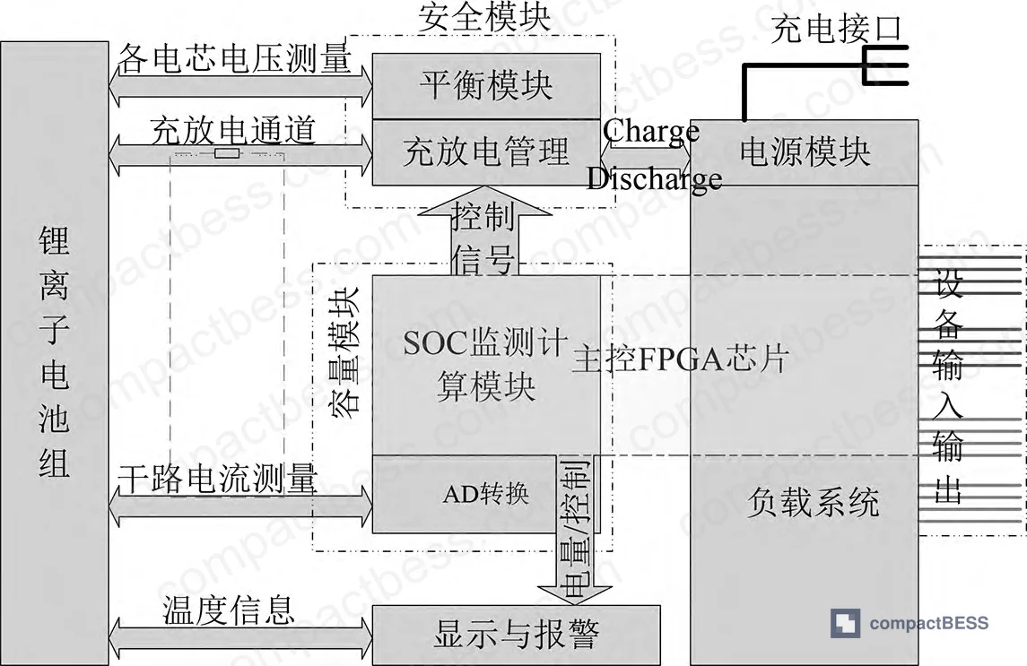
The safety framework for mobile lithium storage breaks into four layers: module structure, material selection, BMS functionality, and cell-level thermal control. Failures in any single layer can cascade. Critically, these layers interact — a poor thermal management design will stress the BMS’s temperature compensation logic, and a BMS with coarse SOC resolution will fail to catch early-stage overcharge conditions before they become thermal events.
Primary safety threat vectors identified in mobile storage:
- Overcharge and overvoltage at cell level — leads to smoking, fire, electrolyte leakage
- Overcurrent at pack level — triggers uncontrolled heat generation
- System-level overvoltage exposure — creates electric shock risk for field personnel
- Thermal runaway propagation — amplified by poor inter-cell isolation in the module structure
- Inadequate temperature monitoring — allows high-temperature conditions to develop before BMS intervention
For LiFePO₄ specifically, the olivine crystal structure provides inherent thermal stability relative to NMC chemistries. The phosphate-oxygen tetrahedral bonding resists decomposition at elevated temperatures, which is why LiFePO₄ is the dominant choice for mobile and stationary storage where safety margin matters more than peak energy density. This doesn’t mean LFP is fire-proof — it means the thermal runaway threshold is higher and the propagation rate is slower, giving the BMS more time to intervene.
The health state (SoH) model used here is worth understanding in detail, because it directly informs your replacement cycle decisions:
Capacity-based SoH: SoH = (Cᵢ / C₀) × 100%, where Cᵢ is the EKF-estimated current capacity and C₀ is the rated nominal capacity.
Resistance-based SoH: SoH = (Reol − Rᵦ) / (Reol − Rₙ) × 100%, where R_eol is set at 1.6× the measured baseline internal resistance.
The internal resistance threshold of R_eol = 1.6 × Rᵦ is the end-of-life trigger. This is a commonly used heuristic in field maintenance systems — a 60% increase in internal resistance generally marks the point where capacity fade and efficiency loss make the pack uneconomical to continue operating.
SoH simulation results across three cycles:
| Cycle | Capacity (Ah) | SoH (Capacity-Based) | Internal Resistance (Ω) | SoH (Resistance-Based) |
|---|---|---|---|---|
| 1 | 1,400 | 100% | 0.030073 | 99.91% |
| 2 | 1,400 | 100% | 0.030042 | 99.96% |
| 3 | 1,400 | 100% | 0.030005 | 99.98% |
The capacity remained stable at 1,400 Ah across all three cycles, consistent with early-cycle operation on a new pack. Resistance-based SoH exceeded 99.9% in all three cycles. The mild resistance decrease from cycle 1 to cycle 3 (0.030073 Ω → 0.030005 Ω) likely reflects initial conditioning — a known behavior in LiFePO₄ packs during early cycling before long-term degradation sets in.
Honestly, the three-cycle simulation window is the main limitation of this dataset. Real qualification requires 200–500 cycle aging data to characterize resistance rise and capacity fade trajectories. Three cycles tells you the model initializes correctly and tracks early-cycle behavior accurately — it doesn’t tell you how the DEKF handles the inflection point at 80% SoH, which is where most packs in field service start causing operational problems.
Safety Impact Factors: What the BMS Must Catch Before Hardware Fails #
The research outlines a structured mapping of safety failure modes to BMS management responses. Understanding this mapping is directly useful when auditing a supplier’s BMS design documentation.
| Safety Factor | Failure Mode | BMS Response Required |
|---|---|---|
| Cell overcharge / overvoltage | Smoke, fire, electrolyte leakage | Voltage monitoring + charge cutoff |
| Pack overcurrent | Unsafe exothermic reaction | Current limiting + circuit isolation |
| System high voltage exposure | Electric shock risk | Voltage isolation monitoring |
| Insufficient power input | Insufficient battery output | Charge management control |
| Thermal escalation | Thermal runaway propagation | Temperature-triggered charge rate reduction |
Most procurement teams don’t realize that IEC 62619, the international safety standard for stationary and mobile lithium battery systems, was substantially revised and now requires explicit documentation of safety requirements across all four of these control layers — not just protection threshold settings. A BMS datasheet that lists only cutoff voltages and temperature limits without describing the state estimation and health monitoring architecture is incomplete from a compliance standpoint.
In supplier qualification, we reviewed BMS module samples from six vendors for a mobile storage application, and three of the six could not provide evidence of any dynamic SOC correction mechanism during load transients. They were all using static Coulomb counting with no model-based correction — which means SOC drift accumulates over discharge depth without compensation. This isn’t a catastrophic safety failure on day one, but it produces systematic underestimation of remaining capacity under real load profiles, which leads to premature low-SOC cutoffs and shortened effective discharge range.
Practical Guidance for Buyers #
When you’re specifying a BMS for mobile energy storage — whether for a portable power station, a field maintenance unit, or a vehicle-mounted backup system — the algorithm running inside the firmware matters as much as the protection hardware. Suppliers who can only spec protection thresholds without explaining their SOC estimation method are selling you a protection relay, not an intelligent BMS.
Require the following in your technical specification:
- SOC estimation accuracy under dynamic load (target ≤1% error at rated discharge rate)
- Internal resistance tracking with a defined end-of-life threshold (R_eol = 1.6× baseline is the engineering consensus)
- SoH calculation method — capacity-based, resistance-based, or both
- Communication interface with logged state data (CAN bus or RS485 minimum for grid-adjacent applications)
- Compliance evidence under IEC 62619 for industrial/mobile applications or UL 9540 for North American markets
For LiFePO₄ packs specifically, confirm the BMS thermal protection is calibrated for LFP’s chemistry — NMC-tuned systems will have incorrect temperature thresholds for LFP, sometimes triggering false cutoffs or, worse, missing early thermal events.
At CompactBESS, we connect global OEM buyers and engineering teams with verified Chinese manufacturers of BMS modules and complete battery storage systems — if you’re qualifying suppliers for intelligent BMS components or LFP-based mobile storage packs, our team can shortlist manufacturers with documented algorithm-level SOC accuracy data and active IEC/UL certifications.
Need help identifying qualified suppliers for intelligent BMS modules or mobile energy storage systems? Talk to our sourcing team →
Supplier Qualification Questions #
- What is your BMS SOC estimation algorithm, and can you provide test data showing error rates below 1% under dynamic charge/discharge cycling at the rated capacity (e.g., 50 kWh / 1,400 Ah class packs)?
- Does your BMS implement dual-loop state estimation — one filter for fast-changing states (SOC, RC-circuit voltages) and a second for slow-changing parameters (internal resistance R₀, capacity Cₚ) — and if so, what is the parameter update rate?
- What is your defined end-of-life internal resistance threshold relative to baseline — specifically, is R_eol set at 1.6× baseline internal resistance, and how is R₀ measured and logged during operation?
- Can you provide capacity-based and resistance-based SoH calculation outputs from your BMS firmware, and show SoH tracking data across at least 50 charge/discharge cycles demonstrating the model’s response to resistance drift?
- What are the specific overcharge voltage cutoff, overcurrent trip threshold, and thermal shutdown temperature programmed into your BMS protection module, and how are these parameters validated against the cell chemistry’s safety envelope per IEC 62619 or GB/T 34131?
Sourcing Checklist #
- [ ] BMS SOC estimation error is documented at ≤1% under rated load cycling (not just static OCV measurement)
- [ ] Supplier provides internal resistance tracking data with R_eol threshold defined at ≤1.6× baseline resistance per the capacity-based SoH model
- [ ] SoH output from BMS firmware is validated against both capacity-fade and resistance-rise criteria across a minimum of 3 documented charge/discharge cycles
- [ ] BMS architecture includes separate estimation loops for fast-state variables (SOC) and slow-state parameters (R₀, capacity) — Dual EKF or equivalent
- [ ] Protection module covers all five safety vectors: cell overvoltage cutoff, pack overcurrent isolation, system overvoltage monitoring, temperature-triggered charge rate reduction, and short-circuit circuit break
- [ ] Battery pack uses LiFePO₄ (LFP) chemistry with confirmed thermal stability rating and BMS thresholds calibrated specifically for LFP (not NMC-tuned firmware)
- [ ] Communication interface supports real-time state data logging via CAN, RS485, or equivalent protocol suitable for remote monitoring
- [ ] Product holds active third-party certification under IEC 62619, UL 9540, or UN 38.3 for transport qualification
Key Specifications Table #
| Parameter | Recommended Value | Verification Method |
|---|---|---|
| SOC Estimation Error (Charge) | ≤0.3% under single-cycle conditions; ≤1.0% under multi-cycle dynamic load | Simulated or hardware-in-loop charge cycling at rated capacity; compare EKF/DEKF output vs. reference coulomb counter |
| SOC Estimation Error (Discharge) | ≤0.58% under single-cycle conditions | Constant-current discharge at 1C rate; measure deviation from reference at 10-second intervals |
| Internal Resistance (Baseline, 1,400 Ah LFP pack) | ~0.030 Ω at early cycle; R_eol ≤ 1.6× baseline | HPPC test (Hybrid Pulse Power Characterization) or EIS (Electrochemical Impedance Spectroscopy) |
| SoH Threshold (Capacity-Based) | ≥80% of rated capacity (C₀) before replacement flag | Capacity measurement via full charge/discharge cycle; SoH = (Cᵢ / C₀) × 100% |
| SoH Threshold (Resistance-Based) | ≥0% before Reol trigger; Reol defined as 1.6× measured baseline Rᵦ | BMS firmware output; cross-check with impedance measurement at defined SOC window (e.g., 50% SOC) |
| Battery Voltage Error | ≤0.13% on charge; ≤1.05 × 10⁻⁴ on discharge | Model voltage vs. measured terminal voltage during cycling |
Can’t find a supplier meeting these specs? Submit your requirements and we’ll match you within 48 hours.
Frequently Asked Questions #
Q1: What is the difference between EKF and DEKF in a BMS, and does it matter for procurement?
It matters significantly. A standard Extended Kalman Filter (EKF) estimates SOC but treats internal resistance and capacity as fixed constants. A Dual Extended Kalman Filter (DEKF) runs two parallel filters: one tracking fast-changing states (SOC, RC-circuit voltages) and one continuously re-estimating slow-changing parameters (internal resistance, capacity). As the battery ages and resistance drifts, the DEKF compensates in real time — the EKF doesn’t. In the simulation data reviewed, DEKF delivered lower absolute deviation than EKF in four of six charge/discharge cycle comparisons, with charge-cycle error dropping from 0.0094 to 0.0059 on cycle 1. For any mobile storage application with variable load profiles, DEKF-class estimation is the minimum you should specify.
Q2: Why is LiFePO₄ the preferred chemistry for mobile energy storage safety applications?
LFP’s phosphate-oxygen tetrahedral crystal structure is more thermally stable than the layered oxide structures in NMC or NCA chemistries. The decomposition temperature is higher, and thermal runaway propagation is slower — which gives the BMS more reaction time to intervene. For mobile applications where the pack may operate without continuous remote monitoring, that margin is operationally significant.
Q3: What does an internal resistance of 0.030 Ω tell me about a 1,400 Ah pack’s health?
At early cycle, 0.030 Ω is consistent with a healthy, unused LFP pack at this capacity class. The end-of-life resistance trigger is set at 1.6× this baseline — approximately 0.048 Ω. When resistance reaches that threshold, capacity fade and efficiency loss typically make continued operation uneconomical. The simulation showed resistance actually decreasing slightly from cycle 1 (0.030073 Ω) to cycle 3 (0.030005 Ω), which reflects normal early-cycle conditioning behavior.
Q4: How do I verify a supplier’s claimed SOC accuracy?
Request hardware-in-loop (HIL) or MATLAB simulation data showing SOC estimation error across a minimum of three full charge/discharge cycles at rated load. The data should show both the estimated SOC trajectory and the reference SOC, with absolute error calculated at each timestep. Charge-cycle error below 0.5% and discharge-cycle error below 1.0% are reasonable targets for a properly tuned DEKF implementation. Be skeptical of suppliers who can only show static accuracy at rest — dynamic accuracy under load is what determines real-world performance.
Q5: Is a three-cycle simulation enough to qualify a BMS?
No. Three cycles confirms the model initializes correctly and tracks early behavior accurately, but it doesn’t capture the degradation curve. You need aging data across 200–500 cycles to validate how the DEKF handles resistance rise and capacity fade over the pack’s service life. For initial supplier qualification, use three-cycle data as a minimum baseline — then require extended cycling data (to at least 20% capacity fade) before final approval for volume procurement.
Published by compactbess.com Technical Team | Request a sourcing quote
For deeper background on BMS communication protocols relevant to mobile storage integration, see BMS Communication Protocols and SOC Estimation Methods in the CompactBESS technical library.
Data source: State Estimation and Safety Monitoring of Mobile Lithium Battery Energy Storage Systems Using Dual Extended Kalman Filtering, H. Zhang et al., Journal of the Electrochemical Society, 2024


