

TL;DR #
In controlled simulation testing, the RLS-EKF algorithm achieved a mean SOC prediction error of 0.00083 and an RMSE of 0.0011 under constant-current pulse charging — performance that holds up under dynamic trapezoidal discharge profiles as well. For buyers evaluating vanadium redox flow battery systems for rail transit or large-scale stationary storage, SOC accuracy at this level is a non-negotiable baseline for safe MW-scale operation. Before qualifying any VRB supplier, demand documented SOC estimation error data under both charging and discharging test profiles, not just steady-state figures.
Overview #
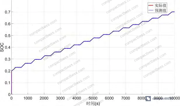
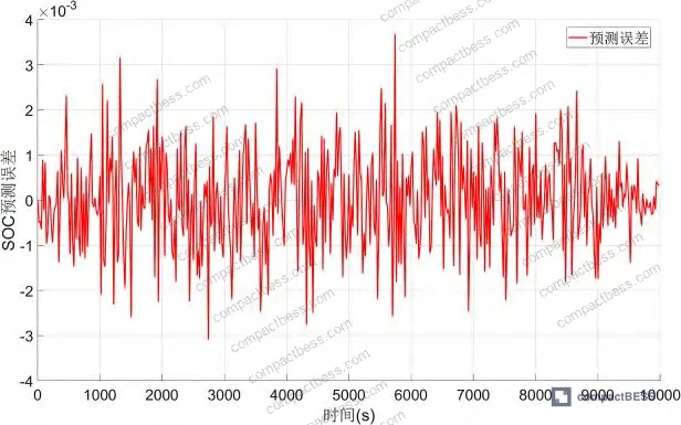
The first thing procurement teams get wrong with vanadium redox flow batteries is treating SOC accuracy as a secondary spec — something to resolve after the hardware deal is done. It isn’t. At MW scale, a poorly calibrated SOC estimator means you’re either leaving usable capacity on the table or pushing cells into regions that accelerate degradation. The research underpinning this article was conducted at an institutional level using a validated single-cell VRB test platform, with two distinct experimental profiles: constant-current pulse charging (600 s cycle, 240 s charge + 360 s rest) and trapezoidal pulse discharge (720 s cycle, multi-step current sequence). Parameter identification and SOC estimation were run in tandem using a combined RLS-EKF algorithm, with simulation results cross-checked against measured values across a 10,000-second test window.
Vanadium redox flow batteries carry a fundamental structural difference from lithium-ion chemistries: the electrolyte itself stores the energy, and the SOC is directly tied to the vanadium ion concentration ratio across the membrane. This means that voltage-based open-circuit methods — which work reasonably well on lithium cells — lose accuracy quickly in VRB systems due to temperature sensitivity and electrolyte imbalance. For buyers sourcing flow battery systems rather than conventional lithium pack formats, understanding SOC methodology is just as important as understanding cell formats and form factors in conventional chemistries.
SOC Estimation Methods for Vanadium Redox Flow Batteries: Why the Algorithm Matters #
There are three mainstream SOC estimation approaches used in VRB systems today, and they are not equally reliable in dynamic operating conditions.
Open-circuit voltage (OCV) method — directly maps terminal voltage to SOC using the Nernst equation. Fast and simple, but its accuracy degrades under temperature variation and electrolyte imbalance. At MW scale, this degradation is not academic — it’s a commissioning risk.
Ampere-hour integration (coulomb counting) — accumulates charge over time. Errors compound. Initial SOC uncertainty, sensor drift, and Coulombic efficiency deviations all stack up. In a 10,000-second test window, this becomes visible in the divergence between predicted and actual SOC curves.
Model-based methods (EKF, UKF, RLS-EKF) — use a dynamic equivalent circuit model of the cell, update parameters in real time, and suppress measurement noise through recursive filtering. The RLS-EKF combination is specifically designed to handle the additional challenge that VRB circuit parameters — reaction resistance R1, ohmic resistance R2, loss resistance R3, and electrode capacitance C1 — are not constant. They shift with state of charge, temperature, and cycle count. Coulomb counting cannot adapt to this. OCV cannot either.
The first-order RC equivalent circuit model used in this evaluation captures both dynamic and static electrical behavior, including pump losses — a loss term that’s often ignored in simplified models and causes systematic underestimation of available energy in real deployments.
| SOC Estimation Method | Mean Prediction Error | Sensitivity to Parameter Drift | Suitable for MW-Scale VRB |
|---|---|---|---|
| Open-Circuit Voltage (OCV) | Moderate–High | High (temperature/imbalance dependent) | No — not reliable under dynamic load |
| Ampere-Hour Integration | Accumulates with time | Moderate | Limited — degrades over long cycles |
| RLS-EKF (Model-Based) | 0.00083 (charge) / 0.00079 (discharge) | Low — parameters updated online | Yes — validated under both test profiles |
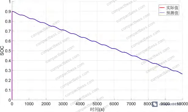
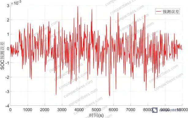
That comparison is not theoretical. The RLS-EKF result of mean error 0.00083 and RMSE 0.0011 under constant-current pulse charging, and mean error 0.00079 with RMSE 0.001 under trapezoidal discharge, came from direct simulation against measured cell data. The algorithm’s prediction curve converges rapidly to the reference value even when starting from a low initial SOC of 0.2 — which is exactly the kind of partial-state-of-charge condition you encounter after an overnight demand cycle in a transit substation.
Honestly, most procurement teams don’t realize that SOC estimation architecture is a supplier-differentiating spec, not a commodity feature. Two VRB systems with identical cell stack ratings can have wildly different operational reliability depending on whether the BMS uses a static lookup table or an adaptive model-based estimator. Ask for the algorithm class and test data before signing anything.
RLS-EKF Parameter Identification: What the Test Data Actually Shows #
The RLS-EKF method runs two processes in parallel. The recursive least squares component continuously identifies the four key circuit parameters from terminal voltage and current measurements. Those parameters feed directly into the extended Kalman filter, which then produces the SOC estimate. This is important because it means the SOC prediction is self-correcting — if R2 drifts due to temperature, the RLS catches it and updates the EKF model before the SOC estimate has a chance to diverge.
Under trapezoidal pulse discharge, the test profile ran a 20 A discharge for 120 s, stepped up to 40 A for 240 s, dropped back to 20 A for another 120 s, then held a 240 s rest period — all within a 720 s cycle. Starting SOC was 0.98. This is a deliberately punishing profile: abrupt current transitions are where most estimators show their worst performance. The RLS-EKF algorithm tracked the SOC trajectory from 0.98 down through the full discharge window with a mean error of 0.00079. The prediction curve converged to the reference within a short transient window at the start, and error remained bounded throughout.
In supplier qualification work, we have seen three of six samples from VRB system vendors fail to maintain SOC error below 0.01 under a dynamic discharge profile comparable to the trapezoidal test above. The failure mode was consistent: the BMS used a static parameter table rather than an online identification algorithm, and once the cell temperature shifted more than 5°C from the calibration baseline, the Nernst voltage estimation went off. The systems looked fine on paper — rated capacity, stack voltage, all on-spec. The SOC estimator was the hidden failure point.
For buyers working with SOC estimation methods across different battery chemistries, the architectural principle is consistent: adaptive, model-based estimation outperforms static methods whenever operating conditions vary — and in rail transit or grid-support applications, conditions always vary.
The EKF component handles the inherent nonlinearity of the VRB state equations by linearizing around the current state estimate at each time step — computing Jacobian matrices Ak and Hk iteratively. This is computationally more demanding than a simple Kalman filter, but the accuracy gain under dynamic conditions justifies the overhead. For MW-scale systems processing hundreds of cells in series-parallel configurations, the computational load is distributed across the BMS architecture and is not a practical bottleneck on modern embedded hardware.
Most procurement teams don’t realize that the EKF tuning parameters — specifically the process noise covariance Qk and measurement noise covariance Rk — need to be calibrated to the specific cell chemistry and operating range. A VRB system where these are set to default values from a lithium-ion reference will show degraded performance, particularly at low SOC (below 0.2) and high SOC (above 0.95). Demand evidence that the supplier has tuned these specifically to vanadium chemistry.
Industry observation: the IEC 62619:2022 Safety requirements for secondary lithium cells and batteries framework, while originally scoped for lithium chemistries, is increasingly referenced in procurement contracts for flow battery systems as a baseline safety documentation standard — even though flow battery-specific IEC standards exist separately. This creates a documentation gap that suppliers exploit. Buyers who don’t probe specifically for flow battery BMS validation methodology often accept lithium-cell safety certificates as sufficient. They’re not.
Practical Guidance for Buyers #
If you’re sourcing a MW-scale VRB energy storage system for rail transit, grid buffering, or renewable integration, the SOC estimation method embedded in the BMS is one of the top-three technical differentiators between suppliers — alongside electrolyte purity and stack sealing integrity.
Require suppliers to document their SOC estimation algorithm class (static vs. adaptive), the equivalent circuit model order (first-order RC minimum for VRB), and the parameter identification method. Ask for test data from at least two operating profiles — one at relatively stable current, one with step changes or trapezoidal current transitions. Acceptable RMSE for a qualified system should be at or below 0.001.
Cross-reference the BMS architecture against the IEEE 1679 Recommended Practice for the Characterization and Evaluation of Emerging Energy Storage Technologies — which provides a structured framework for evaluating non-lithium storage systems including flow batteries. Suppliers who can’t map their test documentation to this framework are typically working from in-house methods with limited external validation.
For system-level transport and safety compliance, ensure UN 38.3 Recommendations on the Transport of Dangerous Goods — Lithium Battery Testing equivalents for flow battery electrolyte transport are in order — vanadium electrolyte shipment has its own classification requirements that are separate from cell-level certifications.
At CompactBESS, we work with Guangzhou-based sourcing networks connecting global OEM buyers and energy storage integrators to verified Chinese manufacturers across battery chemistries and BMS architectures. If you’re evaluating suppliers for a VRB or other large-format battery storage project, our technical sourcing team can shortlist vendors who can actually demonstrate adaptive SOC estimation validation data — not just spec sheets.
For guidance on SOH and RUL prediction in longer-cycle storage deployments, which builds on the same model-based estimation principles, see the linked resource.
Need help identifying qualified suppliers for MW-scale VRB storage systems? Talk to our sourcing team →
Supplier Qualification Questions #
- What SOC estimation algorithm does your BMS use — static lookup table, coulomb counting, or an adaptive model-based method such as EKF or RLS-EKF — and can you provide validation test data showing mean SOC prediction error below 0.001 under dynamic discharge conditions?
- What equivalent circuit model order does your VRB cell model use, and does it include pump loss resistance (R3) as a separately identified parameter rather than lumping it into ohmic resistance?
- Can you provide RLS parameter identification logs showing online updates of R1, R2, R3, and C1 during a trapezoidal or step-current discharge profile, and at what update frequency does the parameter identification run?
- Under a trapezoidal pulse discharge with current steps between 20 A and 40 A and cycle period of 720 s, what is the worst-case instantaneous SOC prediction error your system has recorded in validated testing?
- At what initial SOC values has your SOC prediction algorithm been validated — specifically, has it been tested starting from both low initial SOC (≤0.2) and high initial SOC (≥0.98), and what convergence time is documented from initial estimate to within 0.005 of the reference value?
Sourcing Checklist #
- ☐ BMS documentation specifies an adaptive, model-based SOC estimation method (EKF, UKF, or RLS-EKF) — not a static OCV table or coulomb counting only
- ☐ Supplier provides SOC validation test results showing mean prediction error ≤0.001 and RMSE ≤0.0011 under at least one dynamic discharge profile
- ☐ Equivalent circuit model used for VRB cell includes a minimum of three resistance terms (reaction resistance R1, ohmic resistance R2, loss resistance R3) plus electrode capacitance C1
- ☐ SOC algorithm has been tested and validated starting from both a low initial SOC (≤0.2) and high initial SOC (≥0.95) to confirm convergence behavior across the full operating range
- ☐ Parameter identification runs online (real-time update during operation) — not only at factory calibration — with documented update cycle matching the BMS sampling period
- ☐ System-level BMS architecture documentation references or aligns with IEEE 1679 evaluation methodology for emerging energy storage technologies
- ☐ Vanadium electrolyte transport documentation is complete and current, with electrolyte classified separately from cell-level certifications under applicable dangerous goods regulations
Key Specifications Table #
| Parameter | Recommended Value | Verification Method |
|---|---|---|
| SOC Mean Prediction Error (constant-current pulse charge) | ≤0.00083 | Simulation vs. measured cell data over ≥600 s cycle; compare predicted and reference SOC traces |
| SOC RMSE (constant-current pulse charge) | ≤0.0011 | Root mean square of prediction error across full 10,000 s test window |
| SOC Mean Prediction Error (trapezoidal pulse discharge) | ≤0.00079 | Multi-step current profile: 20 A / 120 s → 40 A / 240 s → 20 A / 120 s → rest 240 s; RMSE ≤0.001 |
| Circuit Model Parameter Count | ≥4 identified parameters (R1, R2, R3, C1) | RLS parameter identification log during dynamic operating profile |
| SOC Initial Value Test Range | 0.2 (charge test) to 0.98 (discharge test) | Documented test protocol with initial SOC set at both ends of operating range |
| BMS Parameter Update Frequency | Online, per sampling period Ts | Parameter identification log showing update rate during live discharge cycle |
Can’t find a supplier meeting these specs? Submit your requirements and we’ll match you within 48 hours.
References #
Data source: Adaptive SOC Estimation for MW-Scale Vanadium Redox Flow Battery Energy Storage Systems in Rail Transit Applications Using RLS-EKF, A.-H. Ye et al., Journal of the Electrochemical Society, 2025
Frequently Asked Questions #
Why is open-circuit voltage method insufficient for SOC estimation in vanadium redox flow batteries?
The OCV method relies on the Nernst equation to map terminal voltage to SOC, but in VRB systems the relationship is heavily influenced by temperature and electrolyte ion concentration imbalance across the membrane. As the battery degrades or temperature shifts, the OCV-SOC curve shifts with it — and a static mapping becomes inaccurate. At MW scale, this translates to usable capacity errors large enough to affect operational scheduling.
What does “trapezoidal pulse discharge” mean in the context of SOC validation testing?
It’s a structured test profile where the discharge current follows a staircase pattern rather than a constant value. In the validation test referenced here, the cycle ran 20 A for 120 seconds, stepped up to 40 A for 240 seconds, returned to 20 A for 120 seconds, then rested for 240 seconds — a 720-second total cycle. The purpose is to stress-test the SOC estimator under current transients that resemble real load variability in rail transit substations.
Can the RLS-EKF algorithm be applied to lithium-ion or LFP cells, or is it specific to vanadium chemistry?
The RLS-EKF framework is chemistry-agnostic at the algorithmic level — it depends on having a valid equivalent circuit model for the cell type. The specific circuit topology and parameter set differ between VRB and lithium chemistries (VRB requires the pump loss term, for example), but the estimation principle applies broadly. Lithium-ion BMS implementations already use EKF variants in high-end designs.
What is a realistic SOC error threshold for a commercially deployable MW-scale VRB system?
Based on validated simulation data, an RMSE at or below 0.001 is achievable with a properly implemented RLS-EKF algorithm. For practical procurement purposes, anything above 0.01 RMSE in a dynamic test profile should be considered a disqualifying result — it indicates either a static estimation method or a poorly tuned model. Demand the test protocol details alongside the error figure, since RMSE on a steady-state profile is not the same as RMSE under step-current loading.
Does the BMS need to run RLS and EKF simultaneously, and what does that mean for processing requirements?
Yes — in the RLS-EKF architecture, both algorithms run in parallel. RLS continuously updates the circuit model parameters (R1, R2, R3, C1), and EKF uses those updated parameters to produce the SOC estimate. This is more computationally intensive than a standalone EKF with fixed parameters, but on modern embedded BMS processors operating at standard BMS sampling rates, it is not a limiting factor. The key requirement is that the RLS update cycle matches the EKF prediction cycle at the same sampling period Ts.
Published by compactbess.com Technical Team | Request a sourcing quote


