

TL;DR #
In electrostatic field simulation of 1500V LiFePO₄ battery systems, the bottom corner of prismatic aluminum-shell cells produces the highest field intensity at 6.75 kV/mm — significantly exceeding the withstand test voltage of 5.37 kV — making it the single most critical insulation failure point in the entire pack. For buyers sourcing cells or pack assemblies targeting DC 1500V systems, standard PET protective film (breakdown voltage 6.5 kV) provides dangerously thin margins at corner positions, and suppliers who cannot specify corner-reinforced wrapping processes are a qualification risk. Require documented insulation reinforcement at cell bottom corners and confirm that any integrated BMS module carries digital isolation rated at ≥6000 VDC before approving a supplier sample.
Overview #
Most procurement engineers evaluating prismatic cells for grid-scale BESS focus on capacity, cycle life, and thermal behavior. Very few are asking the question that actually determines long-term system reliability at 1500V: where exactly does insulation fail first, and what material is wrapping that point? That gap in evaluation methodology is where costly field failures originate.
The engineering analysis behind this article draws on simulation and field qualification work conducted at a major Chinese state-affiliated electrical engineering and energy storage integration group — the kind of organization that has deployed containerized BESS units at grid scale and has the failure case library to back up its recommendations. The methodology combines electrostatic quasi-static field simulation (with aluminum housing set to DC 5370V positive potential, 3mm housing chamfer modeled explicitly) with physical breakdown case documentation and comparative material testing across multiple insulation film types.
The DC bus voltage trend in utility-scale storage has moved decisively from 1000V to 1500V over the past several years, driven by system cost reduction — fewer strings, smaller conductor cross-sections, lower balance-of-plant cost. That voltage step-up is not cosmetic. It changes the insulation stress regime at every level of pack assembly, and the industry’s insulation material standards and qualification practices have not kept pace.
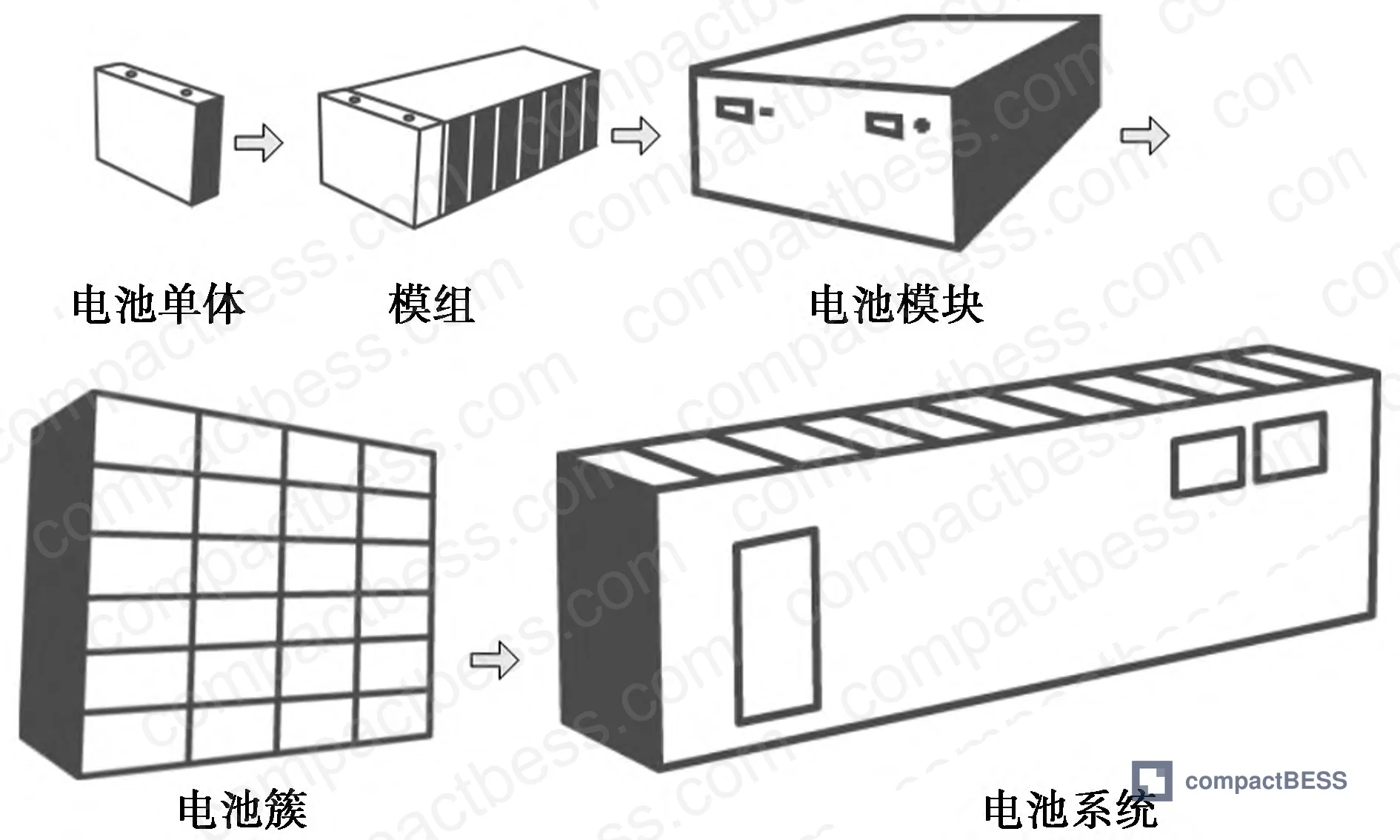
The base system architecture analyzed here is built around 280Ah prismatic LiFePO₄ cells. A 1500V battery cluster consists of 8 battery modules connected in series, each module containing 4 packs in series, each pack containing 13 cells in series, with each cell voltage ceiling at 3.6V. Thermal management for this configuration requires liquid cooling — a design constraint that further complicates insulation material selection due to coolant compatibility and long-term adhesion requirements.
Cell-Level Insulation: Field Intensity Distribution and Material Failure Thresholds #
This is where the data gets uncomfortable for anyone currently specifying standard PET film for 1500V applications.
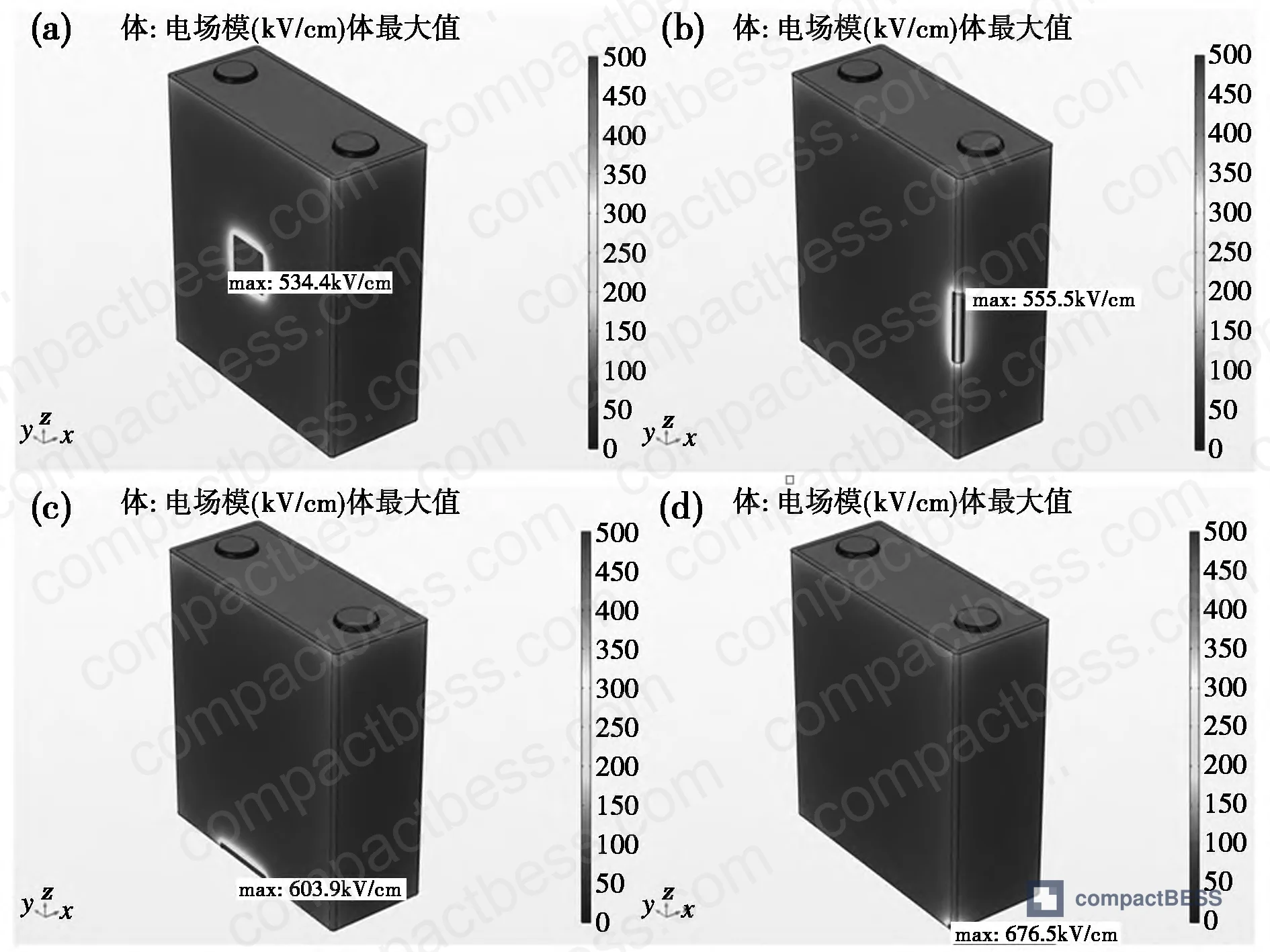
Electrostatic field simulation — with the housing set to a positive DC potential of 5370V, a standard test condition for 1500V systems — yields the following field intensity values at four critical positions on the cell surface:
Cell Surface Field Intensity vs. Withstand Test Voltage
| Position | Max Field Intensity (kV/mm) | Withstand Test Voltage (kV) | Margin Assessment |
|---|---|---|---|
| Large face (flat surface) | 5.34 | 5.37 | Marginal — essentially at limit |
| Side edge | 5.55 | 5.37 | Exceeds test voltage |
| Bottom edge | 6.04 | 5.37 | Significantly exceeds test voltage |
| Bottom corner | 6.75 | 5.37 | Critical — highest risk position |
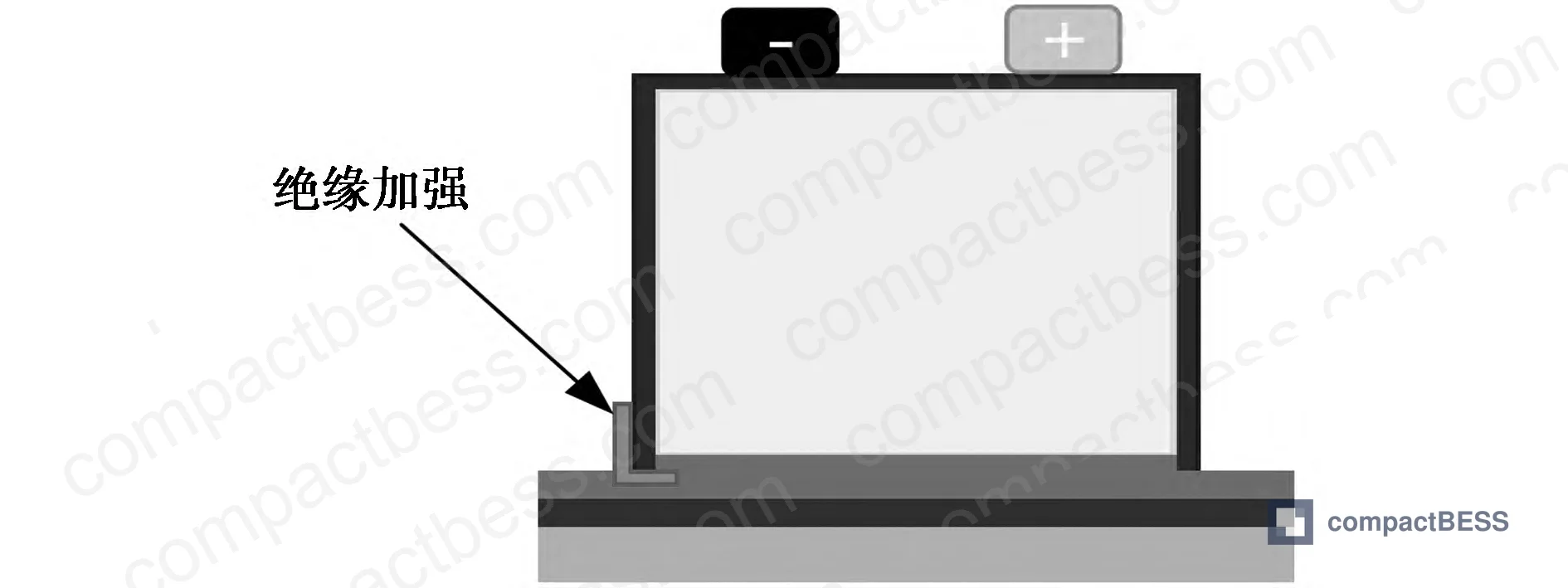
The bottom corner is the weakest insulation point in the entire cell assembly, facing simultaneous exposure to maximum electrical field stress AND mechanical contact damage risk during manufacturing. Standard PET film, with a breakdown voltage of only 6.5 kV at standard thickness, provides essentially zero safety margin at the bottom corner when field intensity reaches 6.75 kV/mm. The side edges carry an additional risk factor: when two cells are placed adjacent, a millimeter-scale air gap exists between the two layers of PET film — and air (dielectric constant 1, conductivity 1.0×10⁻¹⁴ S/m) under high-field conditions is not a reliable insulator.
Honestly, most buyers over-specify cell capacity and under-specify the insulation film. Procurement teams will spend weeks negotiating ±1Ah capacity tolerance but will accept whatever wrapping film the cell supplier applies as a default. At 1000V that might be a defensible shortcut. At 1500V it is not.

Material Electrical Parameters (Simulation Input)
| Material | Relative Permittivity (εr) | Conductivity (S/m) |
|---|---|---|
| Air | 1 | 1.0×10⁻¹⁴ |
| PET insulation film | 3.2 | 1.0×10⁻¹⁶ |
| Aluminum housing | 1.0×10⁸ | 3.593×10⁷ |
| Copper terminal | 1.0×10⁸ | 5.998×10⁷ |
The engineering response to the corner vulnerability involves two approaches. First, physical reinforcement: wrapping the bottom corner with additional insulation layers — using materials like polycarbonate (PC) sheet, mica sheet, or aerogel thermal insulation pads — to both reduce field concentration and protect against mechanical damage during assembly. Second, film material upgrade.
PET vs. PI Film: The Performance Gap Is Not Small #
At equal thickness (0.025mm), the performance difference between standard PET film and polyimide (PI) film is stark:
| Property | PI Film (0.025mm) | PET Film (standard) |
|---|---|---|
| Operating temperature range (°C) | −269 to +250 | −70 to +150 |
| Breakdown voltage (kV) | 37.0 | 6.5 |
| Application status | Limited in BESS | Standard in BESS |
PI film’s breakdown voltage of 37.0 kV versus PET’s 6.5 kV at the same thickness represents a 5.7× improvement in dielectric strength. PI’s rated dielectric strength reaches 300 kV/mm, and it handles continuous operating temperatures up to 350°C — both properties far exceeding anything a standard LiFePO₄ pack environment will demand. The problem is not performance; it’s engineering maturity and cost. Most procurement teams don’t realize that PI film adoption in battery cell protection is still in early-stage field evaluation — the material science is established (it has been used in aerospace and ultra-high voltage reactors for years), but standardized qualification processes for BESS-specific aging, adhesion compatibility, and multi-physics degradation are not yet published. Expect PI-wrapped cells to carry a cost premium and longer lead times until the supply chain matures.
Research on SnO/PI composite film is also worth tracking: at 10% SnO content by mass, the composite achieves a dielectric constant of 456, dielectric loss of only 0.034, tensile strength of 65 MPa, and breakdown strength of 146.9 MV/m — performance characteristics that would be transformative for pack insulation if the material reaches production scale.
BMS Module Insulation: Wiring Harness Failure Modes in 1500V Integrated Pack Designs #
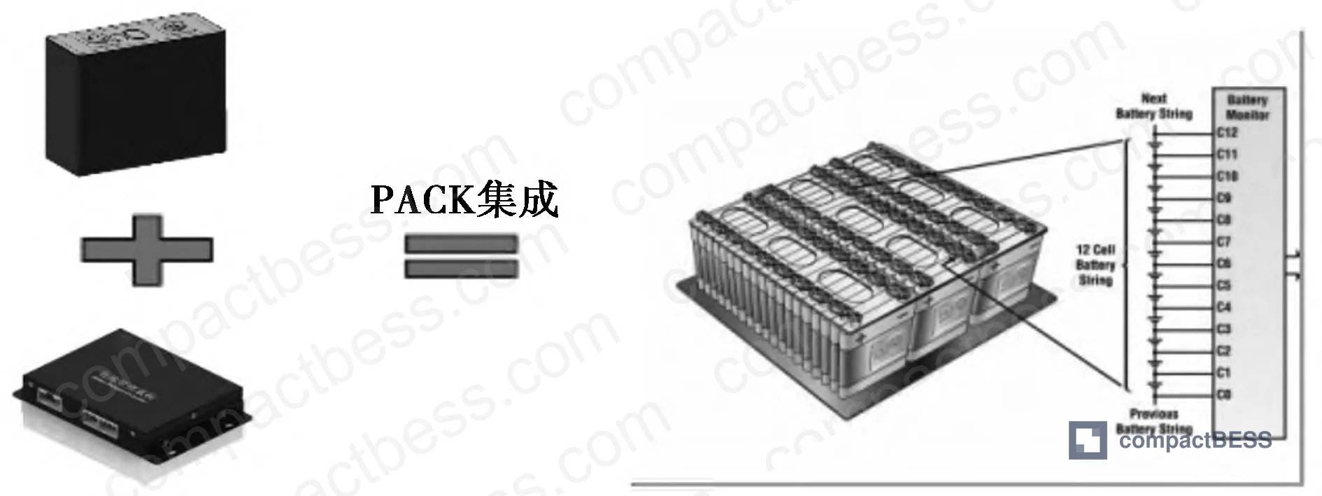
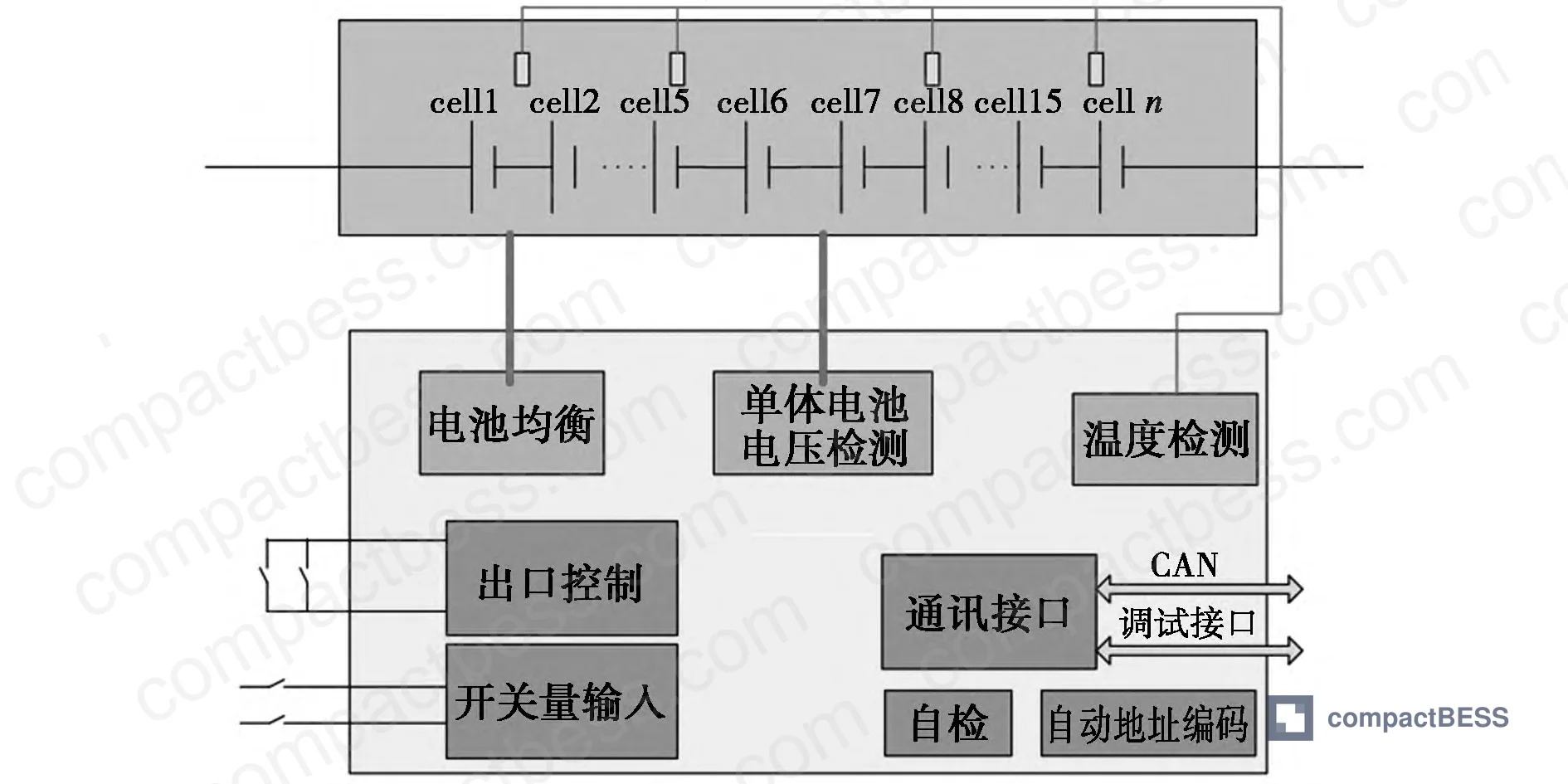
The modern integrated pack design — where BMS circuitry is co-located inside the battery module enclosure rather than in a separate cabinet — creates a new class of insulation risk that is almost entirely absent from most buyers’ qualification checklists.
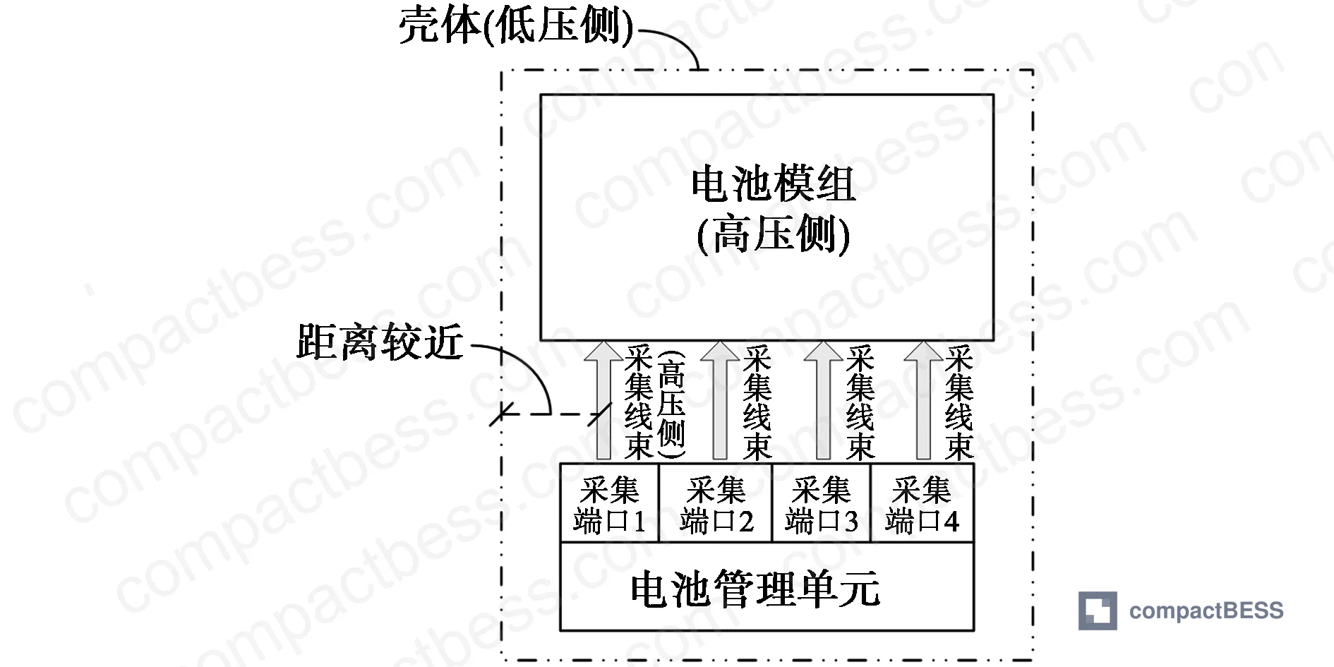
In these integrated designs, the cell voltage and temperature sensing harnesses run from individual cells (which are at high-side potential) to the BMS front-end analog processing chips. The module housing is grounded (low-side). That voltage differential between the harness and housing is a persistent insulation stress point throughout the system’s operating life.
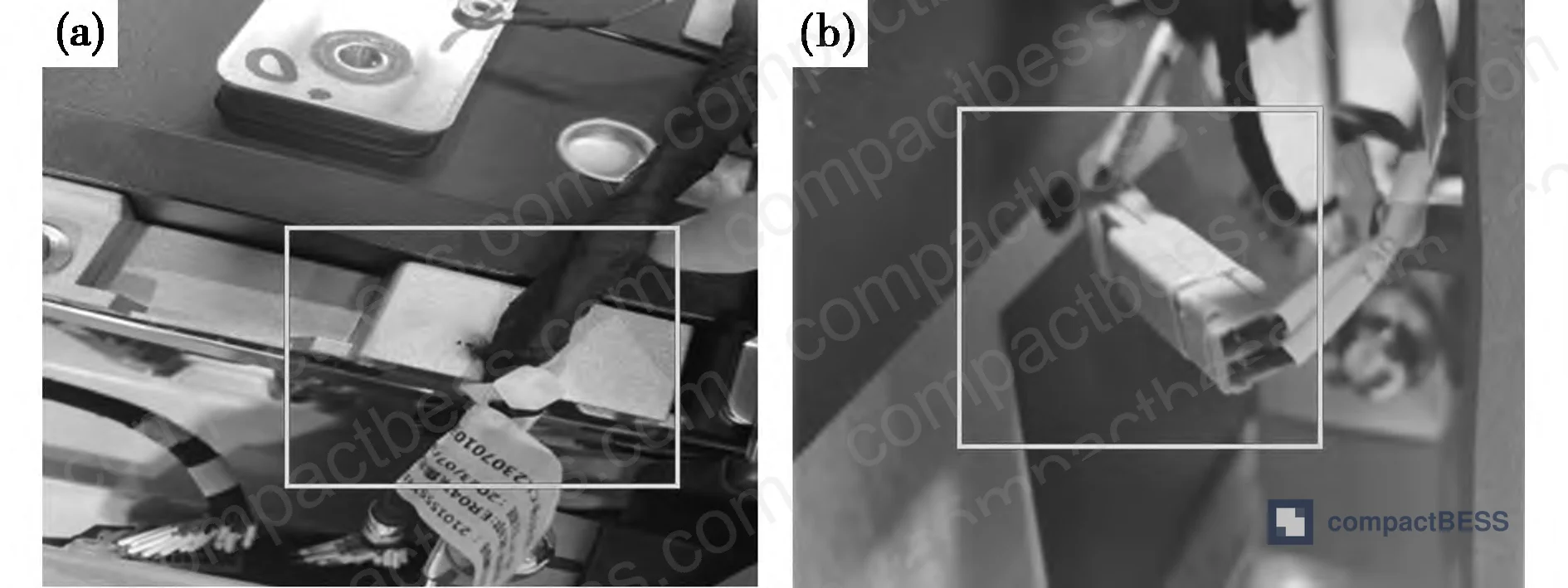
In supplier qualification testing of this configuration, field engineers documented four categories of harness insulation failure observed in deployed units:
- Sensing harness physically pressed against the grounded housing
- Damaged harness sections positioned adjacent to or in contact with the housing
- Harness connectors with exposed metal contacts near the housing
- Harness connector positions too close to housing surfaces
In supplier qualification, we observed that harness insulation failures were often invisible from the outside — the module passed initial hipot testing, but mechanical shift during transport caused the harness to contact the housing wall. This is a transport and installation risk, not just a manufacturing risk, and it won’t show up in a factory audit.
The BMS itself, when properly specified for 1500V operation, should comply with UL 60950 for the circuit design, with digital isolation between the analog front-end chip and the computing chip rated at ≥6000 VDC — exceeding the 5370 VDC withstand test requirement. Voltage sampling accuracy should be ≤±5 mV with a sampling cycle ≤20 ms; temperature sampling accuracy should be ≤±2°C with a sampling cycle ≤100 ms.
Sensing Harness Tape Selection: A Detail That Disqualifies Suppliers #
Harness wrapping tape looks like a commodity purchase. It is not. For 1500V containerized BESS applications, the tape must simultaneously meet requirements across multiple performance dimensions: temperature resistance, flame retardancy, noise damping, electrical compatibility with halogen-free wire insulation, abrasion resistance, and — critically — low outgassing (low fogging).
That last requirement is often missed entirely. In an enclosed container environment, tape that fails the low-fogging requirement will volatilize at elevated temperatures, releasing substances that affect human operators through both sensory irritation and reduced visibility. Beyond comfort, this is a safety risk during maintenance operations.
The adhesive chemistry of common harness tapes — acrylic, rubber, synthetic rubber, polyacrylate pressure-sensitive adhesives — each carries different compatibility profiles with halogen-free wire insulation. Incompatibility manifests as adhesion failure, chemical attack on the wire jacket, or accelerated degradation of the tape’s flame-retardant properties. There is no universal specification here; buyers need to confirm adhesive-to-wire compatibility explicitly for each harness tape used in a qualified BOM.
The potting compound used to encapsulate NTC temperature sensing resistors presents a similar challenge. There is currently no unified industry standard for potting compounds used in BESS temperature sensors. Batch-to-batch variation in potting material performance — combined with variability in cure process control at the supplier level — creates a non-trivial insulation failure risk that is difficult to detect through routine incoming inspection.
Practical Guidance for Buyers #
If you are sourcing prismatic cells or integrated pack modules for a DC 1500V BESS project, the insulation specification conversation with your supplier needs to happen before the commercial negotiation, not after sample approval.
Start at the cell level: require your cell supplier to document the wrapping film type, thickness, and corner reinforcement method. Ask specifically whether their process includes bottom-corner insulation reinforcement — this is the highest-stress location in the system and the one most likely to fail under long-term field conditions. A supplier who can’t answer this question clearly hasn’t qualified their product for 1500V operation.
At the module level, review the BMS harness routing drawings. Confirm that harness paths are mechanically constrained to prevent contact with the housing under transport vibration conditions. Request the digital isolation voltage rating for the BMS front-end circuit — it must be ≥6000 VDC, not merely ≥5370 VDC. The gap between those two numbers is your long-term reliability margin.
The insulation materials selection and certification landscape for 1500V BESS is still maturing. Relevant benchmarks include IEC 62619 for industrial lithium battery safety, IEC 60664 for insulation coordination in low-voltage systems, and UN 38.3 for transport qualification. The EU Battery Regulation 2023/1542 is also introducing traceability and safety requirements that will affect insulation material documentation obligations for product sold into European markets.
At CompactBESS, we work directly with verified manufacturers across China who produce both prismatic cell assemblies and integrated BMS modules qualified for 1500V systems — connecting global OEM buyers and energy storage integrators with suppliers who can answer these technical questions at the spec level, not just the sales level. If you’re at the supplier shortlisting stage and need help separating technically qualified sources from those who aren’t, our sourcing team can accelerate that process.
Need help identifying qualified suppliers for 1500V BESS insulation-rated cell packs and BMS modules? Talk to our sourcing team →
Supplier Qualification Questions #
- What is the documented maximum field intensity at the bottom corner of your cell under DC 5370V test conditions, and what specific insulation reinforcement process do you apply at that location to bring effective insulation margin below the 6.75 kV/mm simulation peak?
- What is the breakdown voltage of the PET protective film applied to your 280Ah prismatic cells — and if it is below 37.0 kV (PI-equivalent), can you provide a qualified alternative wrapping specification for 1500V system integration?
- For your integrated BMS modules, what is the digital isolation voltage rating between the analog front-end chip and the computing chip — does it meet or exceed 6000 VDC, and can you provide the component datasheet and test report confirming this rating?
- What test method and pass criteria do you apply to harness wrapping tape for low outgassing (low fogging) performance in enclosed BESS container environments, and what is your adhesive compatibility verification process for halogen-free wire jacket materials?
- What is your potting compound batch certification process for NTC temperature sensing resistors, and can you provide insulation withstand test data (test voltage, duration, pass/fail rate) for the potted sensor assemblies from your last three production batches?
Sourcing Checklist #
- [ ] Cell insulation film breakdown voltage confirmed ≥37.0 kV (PI film) or ≥6.5 kV (PET) with bottom-corner reinforcement documentation provided
- [ ] Electrostatic field simulation or equivalent validation confirms bottom-corner field intensity ≤6.75 kV/mm under DC 5370V test conditions
- [ ] BMS digital isolation voltage rating confirmed ≥6000 VDC per component datasheet, exceeding system withstand test requirement of 5370 VDC
- [ ] BMS voltage sampling accuracy ≤±5 mV (sampling cycle ≤20 ms) and temperature sampling accuracy ≤±2°C (sampling cycle ≤100 ms) documented in product spec sheet
- [ ] Harness routing drawings reviewed and mechanical constraint method verified to prevent harness-to-housing contact under transport vibration per applicable shock/vibration standard
- [ ] Harness wrapping tape tested for low outgassing performance and confirmed compatible with halogen-free wire insulation (adhesive type documented in BOM)
- [ ] Module/pack assembly complies with IEC 62619 industrial battery safety standard — valid certificate available
- [ ] Transport qualification completed per UN 38.3 — test report covering vibration, shock, and thermal cycling available for the specific pack configuration
Key Specifications Table #
| Parameter | Recommended Value | Verification Method |
|---|---|---|
| Cell bottom-corner insulation film breakdown voltage | ≥37.0 kV (PI film) / minimum ≥6.5 kV (PET with corner reinforcement) | Dielectric breakdown test per IEC 60243; compare against simulation peak of 6.75 kV/mm |
| BMS digital isolation voltage (analog front-end to compute chip) | ≥6000 VDC | Component datasheet + hipot test at 5370 VDC system test condition |
| BMS voltage sampling accuracy | ≤±5 mV, sampling cycle ≤20 ms | Calibrated measurement against reference voltage source across operating temperature range |
| BMS temperature sampling accuracy | ≤±2°C, sampling cycle ≤100 ms | Thermal chamber comparison test against calibrated reference thermometer |
| PET film operating temperature range | −70°C to +150°C (minimum); PI preferred at −269°C to +250°C | Material datasheet confirmation; continuous exposure aging test |
| Cell housing chamfer (corner geometry) | 3 mm minimum radius modeled in field simulation | Dimensional inspection + correlation to FEA simulation model |
| System DC bus withstand test voltage | 5370 VDC (for 1500V-class system) | Applied hipot test per IEC 62619 at module and cluster level |
Can’t find a supplier meeting these specs? Submit your requirements and we’ll match you within 48 hours.
Frequently Asked Questions #
Why is 1500V DC the focus for insulation upgrades rather than 1000V systems?
The transition from 1000V to 1500V is the primary cost-reduction lever in utility-scale BESS — it reduces conductor sizing, cabling cost, and balance-of-plant complexity. But the voltage step-up changes the insulation stress at every component level. Margins that were acceptable at 1000V become inadequate at 1500V, particularly at geometric stress concentration points like cell corners. The field intensity at a cell bottom corner in a 1500V system reaches 6.75 kV/mm — well above the 6.5 kV breakdown voltage of standard-thickness PET film.
Can standard PET film still be used in 1500V cell assemblies, or must suppliers switch entirely to PI?
PET film is not disqualified outright, but it requires supplementary corner reinforcement to be acceptable. The gap between PET’s 6.5 kV breakdown voltage and the 6.75 kV/mm corner field intensity is too small for long-term reliability without additional insulation at the bottom corners using PC sheet, mica, or aerogel pad. PI film at 0.025mm provides 37.0 kV breakdown — a 5.7× margin improvement — but supply chain maturity and cost currently limit its widespread adoption in BESS cell wrapping.
What does “digital isolation rated at ≥6000 VDC” mean in practical terms for BMS qualification?
In an integrated pack module, the cell-side sensing circuits operate at high potential relative to the grounded module housing. The BMS must isolate these circuits from the control electronics. A ≥6000 VDC isolation rating means the barrier component can withstand that voltage continuously without breakdown — giving meaningful margin above the 5370 VDC system withstand test voltage. If a BMS supplier cannot provide the component datasheet showing this rating, the module is not qualified for 1500V operation.
Why does harness tape outgassing matter in a containerized BESS installation?
In an enclosed container environment, tape volatiles accumulate. At elevated temperatures, low-quality harness tape can release adhesive decomposition products that create sensory irritation for maintenance personnel and reduce visibility — both of which increase accident risk during servicing. Low-fogging (low-volatility) tape is not just a comfort specification; it is a safety requirement for enclosed equipment rooms.
Where can I find more technical guidance on cell selection and BMS protection circuit design for high-voltage pack integration?
CompactBESS maintains technical documentation covering cell selection criteria, BMS circuit qualification, and pack safety standards across multiple categories. For 1500V-specific pack architecture questions and supplier matching, the sourcing team can be reached directly through the contact page.
Published by compactbess.com Technical Team | Request a sourcing quote
Data source: Insulation Material Selection and Failure Analysis for DC 1500V Lithium-Ion Battery Energy Storage System Packaging, H. Shi et al., Journal of the Electrochemical Society, 2024
Content reviewed by dr.james.okafor | © compactbess.com — All rights reserved. Unauthorized reproduction prohibited.


