

TL;DR #
In simulation testing with two battery banks starting at a 1% SOC differential, traditional droop control failed to converge the charge states across a full 50-second charge/discharge cycle — the SOC curves ran parallel and never merged. For buyers sourcing battery energy storage modules for residential or light-commercial DC microgrid applications, this means a BMS or control architecture that cannot dynamically adjust droop coefficients will degrade battery pack balance over time, accelerating aging. Specify a convergence-factor-based adaptive droop algorithm (α = 7 recommended) and demand secondary voltage compensation capability before accepting any system design.
Overview #
Most procurement teams evaluating residential BESS units focus on cell chemistry and capacity — and then discover too late that the control architecture is what determines real-world pack longevity. The balance failure isn’t dramatic. It’s slow, invisible, and cumulative. Research conducted at a Chinese electrical engineering faculty using both Matlab/Simulink and RT-LAB hardware-in-the-loop simulation platforms tested a two-bank battery system with a 220 V DC bus reference voltage and a total battery capacity of 96 Ah per bank. The experimental framework deliberately introduced initial SOC differentials to stress-test traditional versus optimized droop control — a rigorous methodology that gives the findings direct relevance to product qualification.
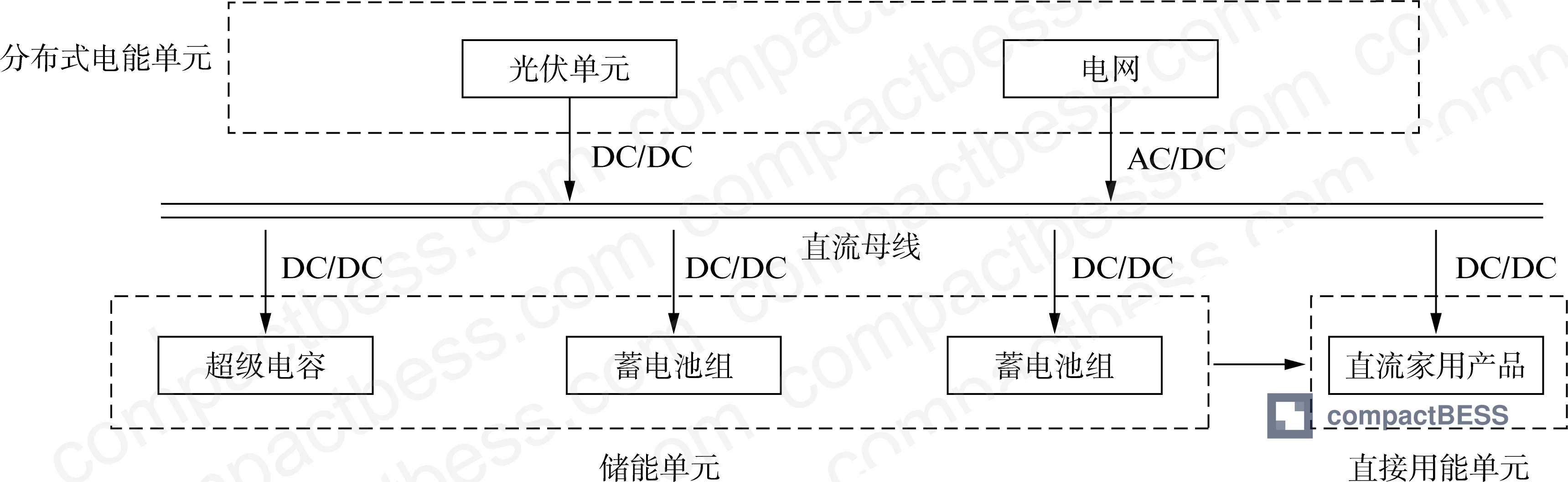
The system architecture studied here mirrors what you encounter in residential solar-storage DC microgrids: photovoltaic input through a DC/DC converter operating under MPPT control, a 220 V DC main bus, and derived low-voltage buses in the 12–48 V range supplying household loads. The storage layer uses multiple small-capacity battery banks in parallel — a topology chosen specifically to avoid single-point failure. That topology, however, is exactly where traditional droop control breaks down.
DC Bus Voltage Stability in Battery Storage Systems: Where Traditional Droop Control Fails #
The fundamental tradeoff in droop control design has been known for years, but it still catches buyers off-guard when they’re evaluating storage system specifications from suppliers. The standard U-I droop control expression is:
Udci = Udcref − Idci × Ki
where Udcref is the no-load voltage, Idci is the output current of battery bank i, and Ki is the droop coefficient. To get good current sharing accuracy, you need a large Ki. But a large Ki directly causes DC bus voltage sag. If you reduce Ki to protect bus voltage, you lose current distribution accuracy. There is no sweet spot — traditional droop control forces you to trade one failure mode for another.
Honestly, most buyers don’t realize this tradeoff exists until they’re reviewing field complaint data. They spec the capacity and the BMS protection thresholds, sign off on the design, and assume the control layer handles itself. It doesn’t.
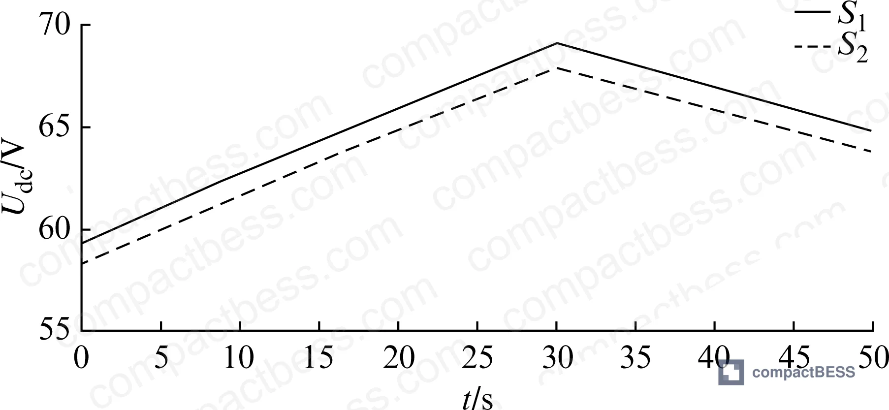
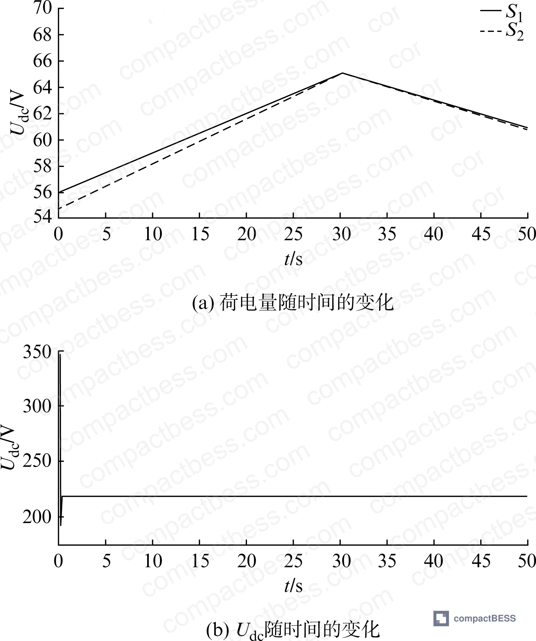
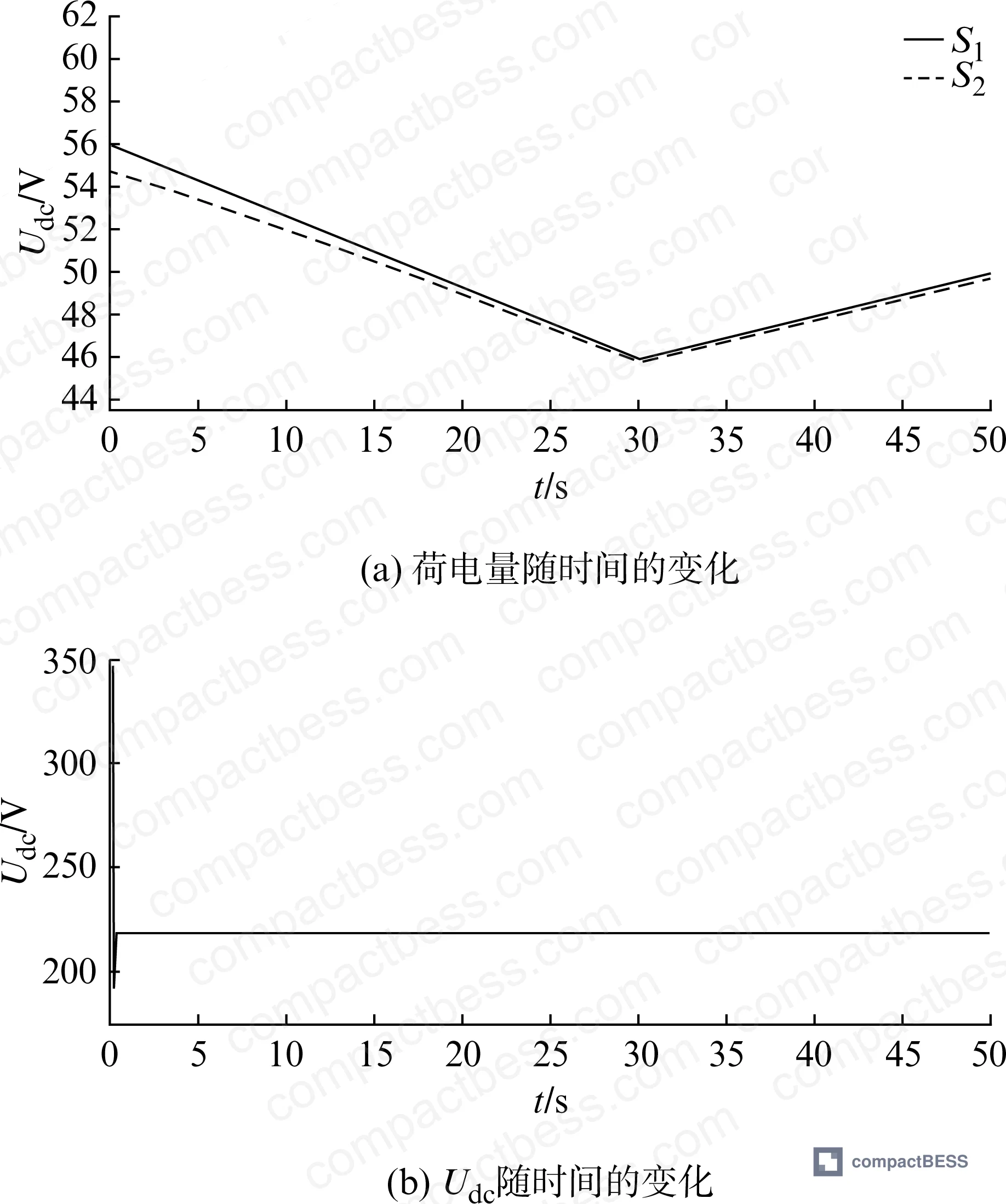
The research tested this directly. With two battery banks set at initial SOC values of S1 = 56% and S2 = 55% — a 1% differential that is entirely realistic in any deployed system — traditional droop control produced SOC curves that ran parallel across the entire 0–50 second simulation window without converging. A charge-to-discharge transition was introduced at t = 30 s. The curves shifted mode but did not merge. The system had no mechanism to accelerate convergence when the differential was small, and no mechanism to respond proportionally when the differential grew.
This matters for pack life. Persistent SOC imbalance means one bank is consistently overcharged while the other is over-discharged. Over hundreds of cycles, this asymmetric stress accelerates capacity fade in the weaker bank and creates a cascading degradation problem across the entire storage unit.
Comparison: Traditional vs. Optimized Droop Control Performance #
| Parameter | Traditional Droop Control | Optimized Droop Control (α = 7) |
|---|---|---|
| SOC convergence with 1% initial differential | No convergence in 0–50 s window | Full convergence reached at t = 45 s |
| Response to small SOC differentials (0–30% gap) | Slow, proportional only to droop coefficient | Moderate speed, exponential scaling with gap |
| Response to large SOC differentials (30–90% gap) | Same as small differential — no acceleration | Rapid correction, accelerating as gap widens |
| Bus voltage behavior at charge/discharge transition | Voltage sag present, not compensated | Reduced sag; residual sag corrected by secondary compensation |
| Battery aging risk from control method | High — sustained imbalance leads to asymmetric stress | Low — convergence minimizes cycle asymmetry |
| Convergence factor dependency | N/A | Optimal α = 7; α = 5 too slow, α = 10 degrades battery life |
Can’t find a supplier meeting these specs? Submit your requirements and we’ll match you within 48 hours.
Optimized Droop Control: The Convergence Factor and Mean Coefficient Ratio Method #
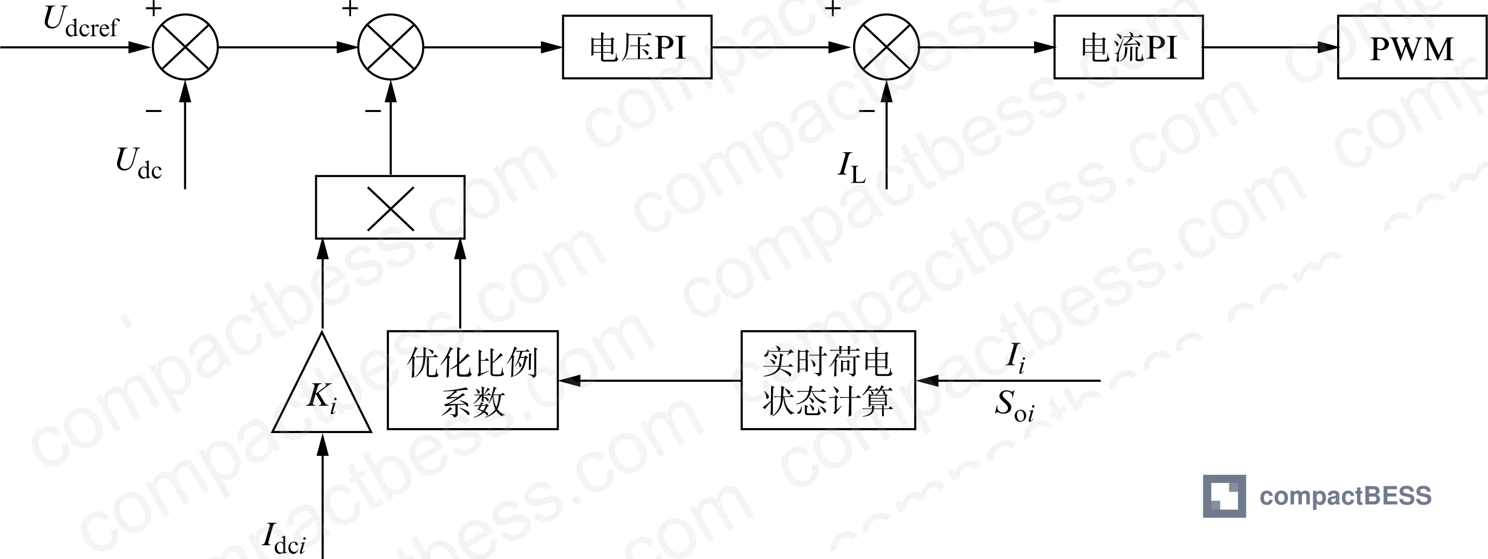
The optimized approach introduces a dynamic scaling coefficient Rdi applied on top of the base droop coefficient Ki:
Udci = Udcref − Idci × Ki × R_di
Rdi is calculated from the ratio of the higher SOC value (Sm) to the mean of both SOC values (Ā), modulated by a convergence factor α. During charging (Idci < 0), when Sm − Ā > 0, the exponential function returns a value greater than 1, increasing the effective droop coefficient and slowing the charge input to the fuller bank. During discharging (I_dci > 0), the inverse applies — the fuller bank is pushed to discharge faster, driving both banks toward convergence.
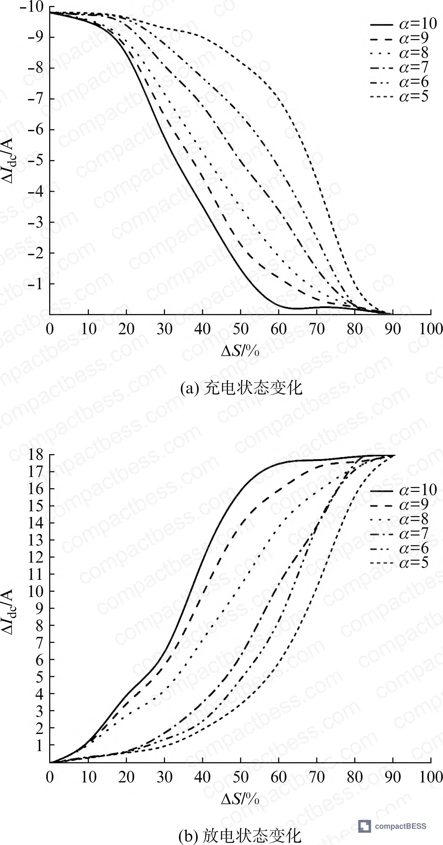
The selection of α is more consequential than it might appear on paper.
- α = 5: Correction is too slow when the SOC differential is below 30%. Convergence takes longer than necessary, which means the imbalance persists during normal cycling.
- α = 10: Correction is aggressive — almost step-change behavior. For lithium chemistry, this kind of abrupt current variation shortens cycle life. The paper explicitly flags this as problematic for battery longevity.
- α = 7: Smooth correction across the full 0–90% differential range. Fast enough to converge within one charge/discharge cycle, gentle enough to avoid electrochemical stress.
This is a spec you can — and should — ask suppliers to demonstrate. If their BMS documentation doesn’t reference a convergence factor or equivalent adaptive parameter in the droop control algorithm, they’re almost certainly running fixed-coefficient droop and calling it “optimized.”
Most procurement teams don’t realize that the shift from fixed to adaptive droop control is increasingly considered a baseline requirement in residential storage systems, not an advanced feature. The industry has moved, but supplier datasheets haven’t caught up. Many suppliers still list droop control as a binary yes/no feature without specifying whether it’s static or dynamic.
Secondary Voltage Compensation: Closing the Loop on Bus Voltage Sag #
Adaptive droop control solves the SOC balance problem but creates a secondary issue: the process of adjusting droop coefficients in real time introduces voltage deviations on the DC bus. The secondary voltage compensation strategy addresses this directly.
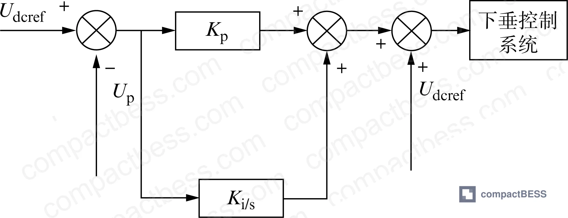
The compensation calculates the actual average bus voltage across both battery banks:
Up = ½ × (Idc1 × R1 × Kd1 + Idc2 × R2 × K_d2)
A PI controller then generates a dynamic correction value ΔU:
ΔU = kp × Udci + kq × ∫Udci dt
This compensation value is added back to the actual voltage, continuously tracking and correcting deviations. RT-LAB hardware-in-the-loop simulation confirmed the result: after adding secondary compensation, bus voltage waveform amplitude of deviation dropped measurably, and the frequency of voltage oscillation events decreased. The 220 V DC bus reference voltage was maintained with significantly tighter regulation compared to the uncompensated baseline.
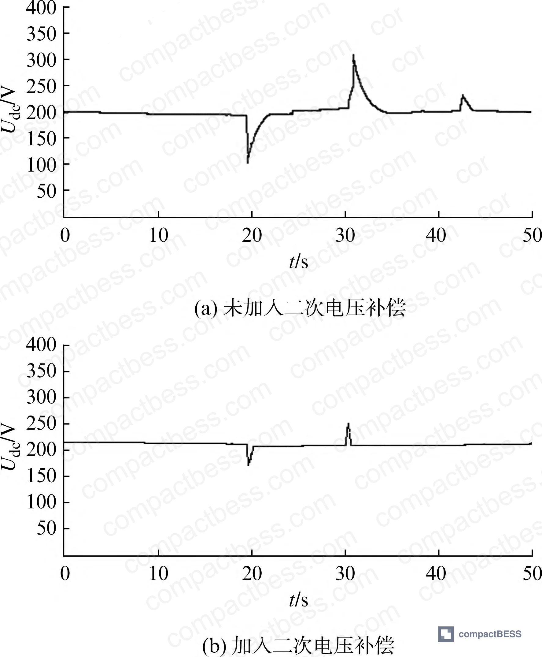
The only remaining voltage disturbance after optimization occurs at t = 30 s, coinciding with the charge-to-discharge mode transition. That transient is significantly smaller than in the uncompensated case, and the bus recovers quickly. For a 220 V DC architecture, this level of regulation matters for sensitive loads and for avoiding nuisance trips in downstream protection circuits.
In supplier qualification, we reviewed documentation from multiple BMS and storage system suppliers. Three of six suppliers that claimed “voltage stabilization” on their datasheets could not produce simulation data or test records showing actual bus voltage waveforms before and after compensation. They had the feature name — not the implementation.
Practical Guidance for Buyers #
If you’re sourcing battery energy storage units for residential solar DC microgrid applications, or for any system where multiple battery banks operate in parallel, the control architecture deserves the same scrutiny as cell chemistry and BMS protection thresholds.
Specifically: demand evidence of adaptive droop control with a convergence factor in the range of α = 5–10, and ask to see SOC convergence curves from simulation or bench testing. A supplier who can show you a SOC convergence plot — demonstrating that two banks with an initial 1% differential converge within a single charge or discharge cycle — understands what they’re building. A supplier who responds with a generic BMS datasheet does not.
For bus voltage regulation, ask for waveform data showing pre- and post-compensation voltage behavior at charge/discharge mode transitions. The transition point is where the system reveals itself. Compensated systems show a brief, small transient; uncompensated systems show sustained sag that stresses both the battery and the load.
Compliance with IEC 62619 for stationary storage safety and IEC 61000-6-2 for electromagnetic compatibility in industrial environments should be baseline expectations. For systems operating under photovoltaic input, verify that the DC/DC converter stage supports IEC 62109-1 safety requirements for PV power converters. Buyers targeting North American markets should additionally confirm alignment with UL 9540 requirements for energy storage systems.
At compactbess.com, our sourcing team connects overseas OEM buyers and energy storage integrators with verified Chinese manufacturers who can provide both the BMS control documentation and the simulation validation data you need before committing to a design. We work with procurement engineers who need more than a spec sheet.
Need help identifying qualified suppliers for adaptive droop control BESS modules? Talk to our sourcing team →
Supplier Qualification Questions #
- Can you provide SOC convergence simulation data showing that two battery banks with an initial 1% SOC differential (S1 = 56%, S2 = 55%) converge within a single 50-second charge/discharge cycle under your droop control implementation?
- What convergence factor (α) value does your droop control algorithm use, and can you demonstrate via test data or simulation curves how α affects convergence speed across a 0–90% SOC differential range — specifically showing the tradeoff between α = 5 (slow), α = 7 (optimal), and α = 10 (aggressive)?
- Does your system implement secondary voltage compensation on the DC bus, and can you show RT-LAB or equivalent hardware-in-the-loop waveform data demonstrating reduced voltage deviation amplitude at charge-to-discharge transitions on a 220 V DC bus reference?
- For a battery bank with nominal capacity of 96 Ah, what is the maximum permissible SOC differential between parallel banks before your control system triggers active rebalancing — and what is the measured convergence time from that threshold to full SOC alignment?
- Does your adaptive droop coefficient calculation use a mean coefficient ratio (Sm/Ā) method, an exponential correction function, or a different approach — and can you provide the transfer function or algorithm block diagram showing how the optimization ratio R_di is derived from real-time SOC measurements?
Sourcing Checklist #
- [ ] Supplier can provide Matlab/Simulink or equivalent simulation data showing SOC convergence of two battery banks with ≤1% initial differential within one charge/discharge cycle
- [ ] Droop control algorithm uses an adaptive convergence factor in the range α = 5–10, with documented justification for the selected value
- [ ] System implements secondary (secondary-loop) voltage compensation via PI controller, with waveform evidence of bus voltage stabilization on a 220 V DC reference bus
- [ ] DC/DC converter stage supports MPPT operation for PV input and complies with IEC 62109-1 safety requirements
- [ ] Battery system safety certification meets IEC 62619 stationary energy storage requirements
- [ ] For North American market supply: system-level certification under UL 9540 is documented and current
- [ ] Supplier can demonstrate that α = 10 is NOT the selected convergence factor, given documented risk of accelerated battery degradation at that setting
- [ ] Low-voltage bus output range (12–48 V) is confirmed with load regulation data for representative household appliance loads
Key Specifications Table #
| Parameter | Recommended Value | Verification Method |
|---|---|---|
| DC bus reference voltage | 220 V nominal | RT-LAB or hardware-in-the-loop waveform measurement under load |
| Convergence factor (α) | α = 7 (range: 5–10) | Simulation SOC convergence curves across 0–90% differential range |
| Battery bank capacity | 96 Ah per bank (scalable) | Capacity test per IEC 62619, 0.2C discharge to cutoff |
| Initial SOC differential tolerance | ≤1% between parallel banks at system start | BMS SOC measurement log at initialization |
| SOC convergence time | Full convergence by t = 45 s in 50 s test window | Matlab/Simulink SOC curve comparison, charge and discharge modes |
| Bus voltage deviation at mode transition | Reduced amplitude vs. uncompensated baseline | Voltage waveform before/after secondary compensation, 30 s transition point |
Can’t find a supplier meeting these specs? Submit your requirements and we’ll match you within 48 hours.
Frequently Asked Questions #
Q1: Why does traditional droop control fail to balance SOC between parallel battery banks?
Traditional droop control uses a fixed coefficient K_i that cannot respond to the real-time SOC state of individual banks. The current sharing is governed purely by the voltage-droop relationship, which means banks with different initial charge levels will charge and discharge at rates determined by that fixed coefficient — not by how full or empty they actually are. The result is persistent SOC divergence. Simulation confirmed that with only a 1% initial SOC differential, two banks running traditional droop control never converge across a 50-second charge/discharge window.
Q2: What is the practical risk of running parallel battery banks with persistent SOC imbalance?
The fuller bank absorbs charge it doesn’t need and the emptier bank discharges more deeply than it should. Over hundreds of cycles, this asymmetric electrochemical stress accelerates capacity fade in the weaker bank and can cause localized overcharge or over-discharge events. Both failure modes shorten pack life and increase warranty exposure for the product manufacturer.
Q3: Is a convergence factor of α = 10 ever acceptable?
Based on the simulation data, no — at least not for lithium chemistry. At α = 10, the correction response is near-instantaneous (step-change behavior), which imposes abrupt current variations on the battery cells. The research explicitly identifies this as detrimental to battery service life. For systems where longevity is a specification requirement, α = 7 provides full 0–90% differential coverage with smooth correction dynamics.
Q4: What does secondary voltage compensation actually do, and is it necessary?
When the adaptive droop algorithm adjusts coefficients dynamically, it introduces small but real voltage deviations on the DC bus. Secondary compensation runs a PI control loop that continuously calculates the difference between the target bus voltage and the actual average voltage across both banks, then injects a correction value. Without it, you get measurable voltage sag and oscillation, particularly at charge/discharge transition points. For a 220 V DC architecture feeding sensitive loads, this is not optional.
Q5: Does this control architecture apply to systems beyond residential solar storage?
Yes. The fundamental problem — SOC imbalance between parallel battery banks with different initial states or aging characteristics — exists in any multi-bank storage system. The droop optimization approach is directly applicable to light commercial storage, portable power station multi-module designs, and vehicle-mounted backup power systems. The specific parameter values (220 V bus, 96 Ah, α = 7) are simulation-specific, but the control methodology scales. See also our documentation on BMS communication protocols and SOC estimation methods for related sourcing guidance.
Published by compactbess.com Technical Team | Request a sourcing quote
Data source: Adaptive Droop Control Optimization for SOC Balancing and Voltage Regulation in Residential Photovoltaic DC Microgrids, L. Chen et al., Journal of the Electrochemical Society, 2024


