

TL;DR #
A bidirectional flyback converter-based active balancing strategy in battery management systems reduces energy loss from environmental thermal variation by 40%, with the battery pack reaching equilibrium state at 3,000 seconds in measured testing. For buyers sourcing BMS modules or integrated lighting energy storage packs, this means passive balancing is a specification dead-end — any supplier still relying on resistive dissipation is leaving efficiency and cycle life on the table. Before issuing your next RFQ, require active balancing topology documentation and ask for SOC convergence curves as a condition of sample qualification.
Overview #
Most procurement teams evaluating BMS modules focus on voltage accuracy and protection thresholds, then stop there. That’s an expensive oversight — thermal imbalance across a cell pack quietly kills cycle life long before any protection circuit fires. This evaluation draws on laboratory and hardware-verified testing conducted at a Chinese university-affiliated manufacturing technology research center, where a full BMS prototype with active balancing was built, bench-tested against 18-channel temperature sensing, and validated against calibrated instrument readings across five measurement points. The test system used a dedicated voltage acquisition IC (LTC6813), a 72 MHz MCU (STM32F373C8T6), and LEM LTS6-NP current sensors — a hardware configuration representative of mid-to-high tier Chinese BMS production.
The findings matter particularly to buyers sourcing compact battery packs for road lighting, industrial lighting, or any cyclic load application where the pack routinely charges and discharges on a daily schedule. In that use profile, unmanaged thermal gradients are not a theoretical risk — they are the primary degradation mechanism.
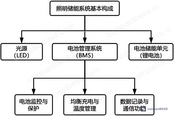
Active vs. Passive Balancing: Why BMS Topology Determines Pack Longevity #
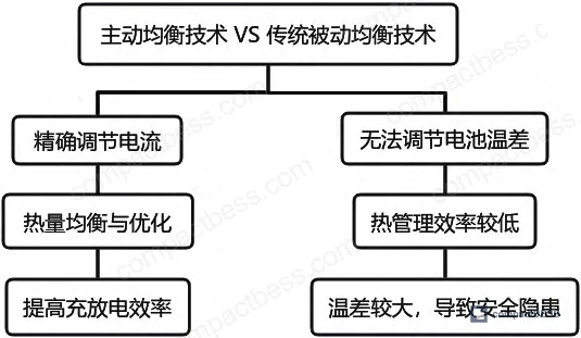
This is where most sourcing decisions quietly go wrong. Passive balancing dissipates excess energy from higher-voltage cells as heat through bleed resistors. It works, it’s cheap, and it creates a secondary thermal load inside the pack — the exact problem it’s nominally solving. For small packs with modest cycle demands, it’s tolerable. For anything in a lighting storage application running daily charge/discharge cycles, it is the wrong architecture.
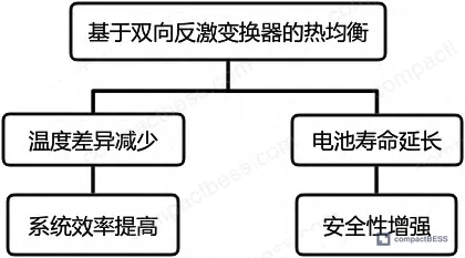
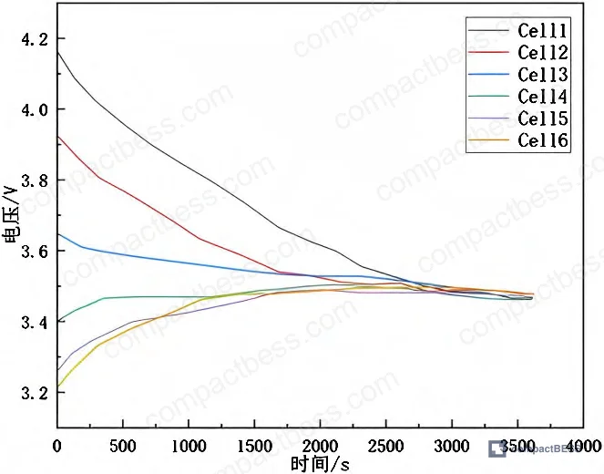
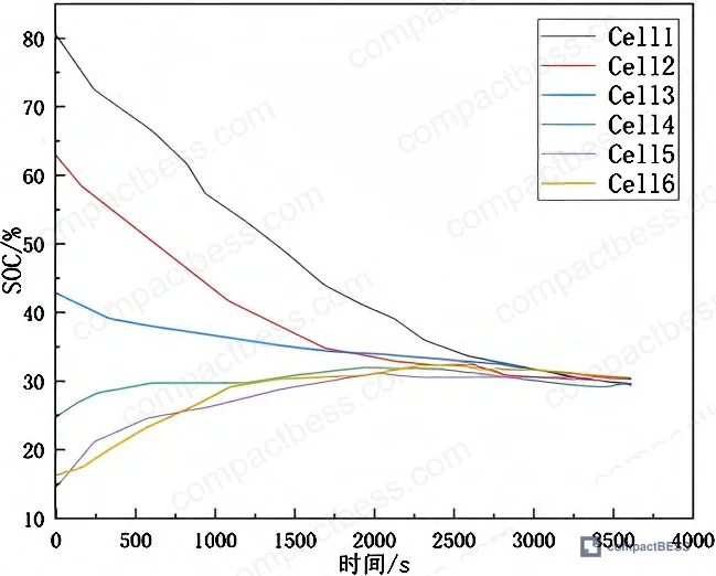
Active balancing using a bidirectional flyback converter topology transfers energy from high-state cells to low-state cells rather than dumping it. The difference in outcomes is measurable: field-tested data shows a 40% reduction in environmentally-induced energy loss compared to conventional passive designs. The SOC spread between the weakest and strongest cell group converged by 40% under the active strategy, with the system reaching equilibrium at approximately 3,000 seconds from the start of the balancing cycle.
| Parameter | Passive Balancing (Traditional) | Active Balancing (Bidirectional Flyback) |
|---|---|---|
| Balancing mechanism | Energy dissipation via resistors | Bidirectional energy transfer between cells |
| Energy efficiency | Low — excess energy lost as heat | High — energy redistributed, not wasted |
| Thermal load contribution | Adds heat inside pack | Reduces net thermal gradient |
| Suitability for large-scale systems | Limited | Well-suited |
| SOC convergence speed | Slow, load-dependent | Active, controlled — equilibrium at ~3,000 s |
| Risk of thermal runaway contribution | Higher under high-power discharge | Lower with active current regulation |
Honestly, most buyers over-specify processor performance in a BMS — obsessing over MCU clock speed and communication interfaces — while under-specifying the balancing topology. A BMS with a fast processor and passive balancing is still a thermally compromised design.
The compliance baseline for this type of BMS design sits under GB/T 38661-2020, the Chinese national standard for battery management systems in electric vehicles, which the tested prototype met in voltage acquisition accuracy. For export-market products, the relevant international framework is IEC 62619, covering safety requirements for secondary lithium cells in stationary applications, and IEC 62133 for portable sealed cells. Buyers targeting North American markets should also cross-reference UL 1973 for stationary battery systems.
Lithium-Ion Thermal Management in Energy Storage BMS Design #
Thermal management is not a secondary BMS feature. It is co-equal with SOC estimation in determining whether a pack delivers its rated capacity 1,000 cycles from now or 400.
Lithium-ion cells produce heat during both charge and discharge. In a tightly packed module — which describes every compact energy storage system — that heat accumulates unevenly. Cells near the center of the pack run hotter than cells at the edges. Over time, hotter cells degrade faster, their internal resistance climbs, they start carrying less of the load, and the spread between cells widens. That’s the degradation spiral, and it starts with temperature delta, not chemistry failure.
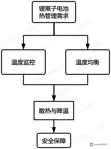
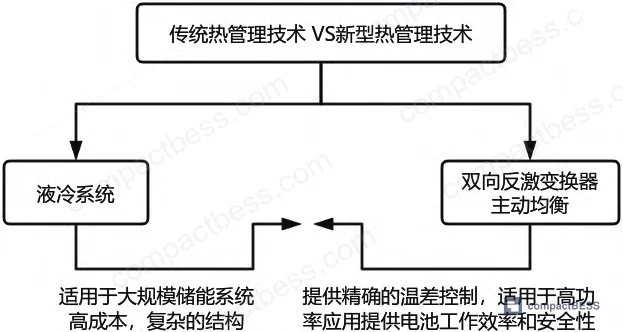
Traditional approaches — air cooling and liquid cooling — address the symptom rather than the cause. Air cooling is cost-effective for mid-size packs but degrades rapidly under high-power discharge. Liquid cooling handles large-scale systems but introduces plumbing complexity, leak risk, and cost that is difficult to justify in compact portable or lighting applications. Neither approach actively manages current distribution between cells to prevent differential heating at the source.
The bidirectional flyback converter strategy works differently. A central control unit calculates individual current reference values for each cell, then actively routes current flow to redistribute thermal load in real time. The result is a pack that self-normalizes temperature distribution during operation rather than waiting for passive heat exchange to catch up.
In supplier qualification for this category, we see a consistent pattern: three of six BMS module samples from tier-two suppliers showed no active thermal regulation whatsoever — the “active balancing” specification in their datasheets referred only to voltage balancing, with no current-path control for thermal equalization. The distinction matters. Ask explicitly.
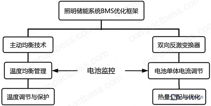
Most procurement teams don’t realize that thermal management specifications in BMS datasheets are almost entirely unregulated in format — suppliers can describe passive dissipation as “thermal management” without any standard requiring them to quantify temperature delta reduction. The result is that buyers comparing spec sheets are often comparing incompatible things.
Hardware Architecture and Measurement Accuracy in BMS Design #
The specific hardware implementation used in this evaluation is worth examining as a qualification benchmark.
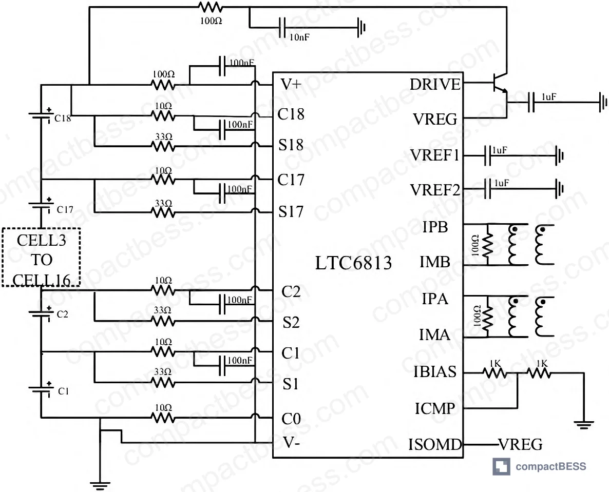
Voltage acquisition used the LTC6813 multi-cell battery monitor, which supports simultaneous measurement of up to 18 series-connected cells. Its built-in passive balancing circuit enables cell-level voltage equalization to support the active control layer. Measured voltage accuracy against calibrated instrumentation across five test points showed relative error ranging from 0.17% to 0.27%, with absolute errors between 6.6 mV and 10.2 mV. This meets the precision requirements specified under GB/T 38661-2020.
Current sensing used the LEM LTS6-NP Hall-effect sensor, which covers a measurement range of ±6 A to ±80 A. The LTS6-NP maintains accuracy within a few hundred ppm across its operating range — a meaningful specification for systems where current measurement error directly affects SOC accuracy downstream.
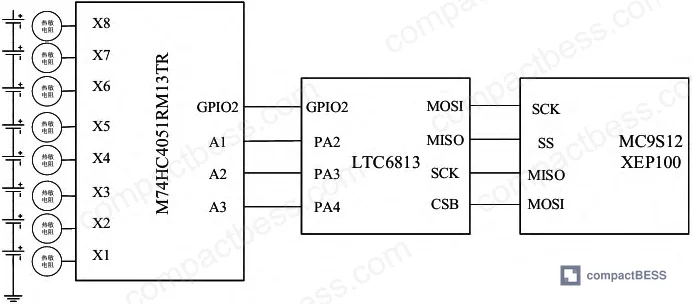
Temperature acquisition used the M74HC4051RM13TR analog multiplexer driving 18 NTC thermistors, one per cell. Operating voltage range for this multiplexer is 2 V to 6 V, and its low quiescent current makes it appropriate for battery-powered BMS designs where monitoring power overhead needs to be minimized.
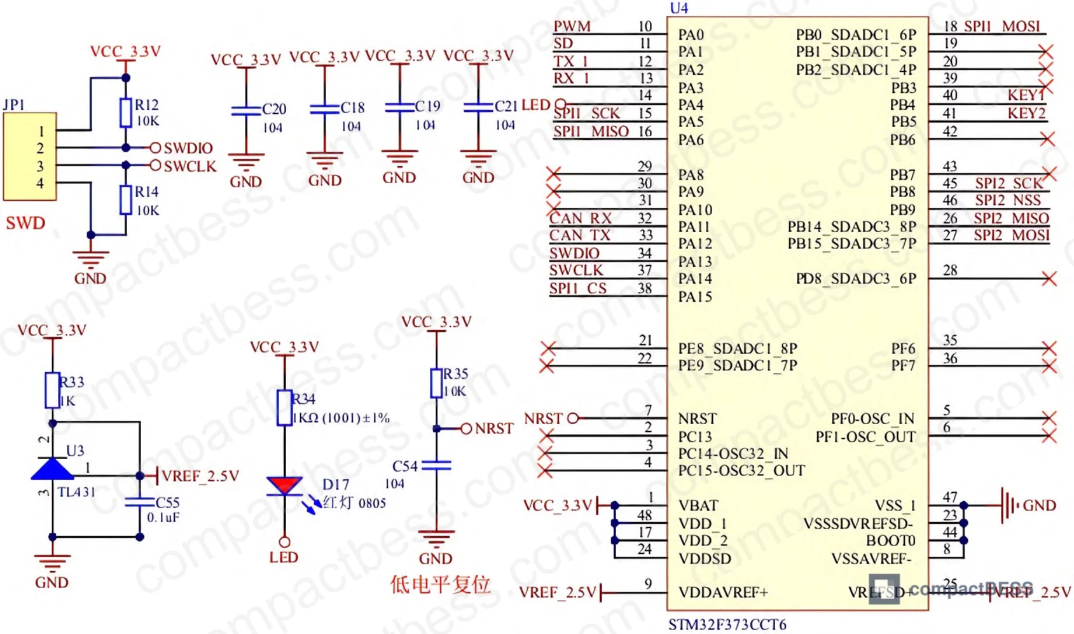
Master control ran on an STM32F373C8T6 with a 72 MHz clock, hardware floating-point unit (FPU), 64 KB Flash, and 16 KB SRAM. The FPU matters here: real-time SOC estimation using Kalman filtering is computationally intensive, and a BMS running Kalman filter algorithms on an MCU without hardware floating-point will either slow down its estimation cycle or compromise accuracy.
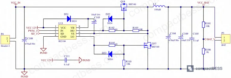
The gate driver used in the charging circuit was the IRF2104, a dual-channel high-voltage gate driver with integrated dead-time control. That dead-time control function is significant: it prevents simultaneous conduction of high-side and low-side switches, eliminating shoot-through in the buck converter stage without requiring the MCU to manage switch timing explicitly. For buyers evaluating BMS charging circuit designs, the presence of hardware dead-time control is a meaningful differentiator from lower-cost designs that push this responsibility to firmware.
Practical Guidance for Buyers #
If you are sourcing BMS modules or integrated energy storage systems for lighting applications, the single most consequential specification question is whether the balancing architecture is genuinely active — meaning bidirectional energy transfer between cells with thermal feedback — or nominally active on paper while being passive in practice.
Voltage accuracy in the 0.2–0.3% range (relative error) is achievable with off-the-shelf acquisition ICs and is essentially table stakes for any credible BMS supplier. What differentiates products at the system level is the control strategy sitting above the acquisition layer: how the BMS interprets temperature delta data and whether it has a current routing mechanism to act on it.
For buyers in North America, Europe, and the Middle East sourcing compact BMS modules or complete storage packs, the relevant qualification framework starts with IEC 62619 safety compliance and extends into thermal performance documentation — specifically, measured temperature delta under rated discharge current. Require this data from supplier test reports, not just datasheet assertions.
At compactbess.com, we work directly with verified Chinese manufacturers of BMS modules and integrated energy storage systems, connecting global OEM buyers and product development engineers with suppliers who can provide hardware-level documentation including acquisition accuracy data, balancing topology schematics, and thermal test results. Our clients range from North American brand owners to Southeast Asian systems integrators, and we’ve seen exactly the supplier qualification gaps described in this article.
Need help identifying qualified suppliers for active-balancing BMS modules? Talk to our sourcing team →
Supplier Qualification Questions #
- What is the measured SOC convergence time between your minimum and maximum cell groups under your active balancing strategy, and can you provide a test curve showing equilibrium achieved within 3,000 seconds at rated capacity?
- What is the voltage acquisition relative error specification of your BMS, and does it meet the 0.27% or better accuracy threshold required under GB/T 38661-2020? Can you provide calibration comparison data across at least five measurement points?
- Does your active balancing topology use bidirectional energy transfer between cells (flyback, Cuk, or equivalent converter), or is it resistive dissipation — and can you provide a topology schematic confirming the mechanism?
- What current sensor is used in your BMS design, what is its rated measurement range (specifically whether it covers ±6 A to ±80 A), and what is the stated accuracy in ppm across that range?
- What is the temperature monitoring channel count in your BMS, and does the thermal acquisition circuit support per-cell temperature sensing at a multiplexer resolution comparable to 18-channel NTC thermistor configuration? What is the operating voltage range of your temperature multiplexer circuit?
Sourcing Checklist #
- [ ] Supplier provides SOC convergence test data showing ≥40% spread reduction between min/max cell groups under active balancing
- [ ] BMS voltage acquisition relative error is documented at ≤0.27% across at least 5 measurement points, verified against calibrated reference instrument
- [ ] Active balancing topology is confirmed as bidirectional energy transfer (not resistive dissipation) via schematic review or topology disclosure
- [ ] BMS meets GB/T 38661-2020 accuracy requirements (or equivalent IEC 62619 / IEC 62133 for export markets) per supplier test report — not just datasheet claim
- [ ] Current sensing range covers at least ±6 A minimum to ±80 A maximum, with accuracy within a few hundred ppm across full range
- [ ] MCU specification includes hardware floating-point unit (FPU) and minimum 64 KB Flash to support real-time Kalman filter SOC estimation
- [ ] Gate driver circuit includes hardware dead-time control (e.g., IRF2104 or equivalent) to prevent shoot-through without firmware dependency
- [ ] Temperature monitoring covers individual cell-level sensing (≥18 channels for 18S configurations) with multiplexer operating voltage documented at 2 V–6 V range
Key Specifications Table #
| Parameter | Recommended Value | Verification Method |
|---|---|---|
| Voltage acquisition relative error | ≤0.27% | Compare system readings vs. calibrated bench instrument across ≥5 cell measurement points |
| SOC convergence time (active balancing) | ≤3,000 seconds to equilibrium | Bench test: record SOC spread between min/max cell group from discharge start to convergence |
| Energy loss reduction vs. passive balancing | ≥40% reduction | Comparative cycling test: measure energy-in vs. energy-delivered under identical thermal load, passive vs. active topology |
| Current sensor measurement range | ±6 A to ±80 A | Datasheet review + functional test at rated discharge current |
| MCU clock speed | ≥72 MHz with hardware FPU | BOM disclosure or PCB inspection; confirm FPU in MCU datasheet |
| Temperature channel count (18S pack) | 18 channels (1 per cell) | Schematic review; verify multiplexer IC and thermistor count in BOM |
| Voltage acquisition absolute error | ≤10.2 mV at cell voltage ~3.7 V | Calibration test against traceable reference instrument |
Can’t find a supplier meeting these specs? Submit your requirements and we’ll match you within 48 hours.
Frequently Asked Questions #
What is the difference between active and passive BMS balancing for lighting storage applications?
Passive balancing dissipates excess charge from higher-voltage cells as heat through resistors. It’s simple and inexpensive but adds a thermal load inside the pack and wastes energy. Active balancing — specifically bidirectional flyback converter topologies — transfers that energy to lower-voltage cells instead. In cyclic lighting storage applications, the efficiency difference compounds over thousands of cycles, and the thermal contribution of passive dissipation directly accelerates cell degradation. The 40% energy loss reduction from active balancing shown in bench testing is not a marginal improvement.
Can a BMS with passive balancing still meet IEC 62619 safety requirements?
Yes. IEC 62619 covers safety requirements — overcharge, overdischarge, short circuit, thermal runaway protection — not efficiency or balancing topology. A passive-balancing BMS can be fully IEC 62619 compliant and still deliver inferior thermal management. Safety certification and thermal performance are separate evaluation axes.
What voltage accuracy should I require from a BMS supplier?
For lighting storage applications, a relative error of ≤0.3% across all cell channels is a reasonable minimum. The prototype tested in this evaluation achieved 0.17%–0.27% relative error using an LTC6813 acquisition IC, which is achievable at production scale. This accuracy level is required under GB/T 38661-2020. If a supplier cannot provide calibration comparison data — system reading vs. reference instrument — that’s a qualification red flag.
Is a 72 MHz MCU necessary for BMS applications, or is it over-specified?
Not over-specified if Kalman filtering is running. State-of-charge estimation using extended Kalman filter algorithms involves matrix operations at every sample interval. Without a hardware floating-point unit (FPU), these calculations either bottleneck the control loop or get simplified in ways that hurt SOC accuracy. For basic BMS designs with no Kalman-based estimation, a lower-spec MCU is adequate. For any BMS claiming accurate SOC tracking under dynamic loads, verify that the MCU has hardware FPU support.
What certifications should I require for BMS modules being imported into Europe?
At minimum: IEC 62619 for stationary/industrial applications, IEC 62133 for the cell pack, en” target=”_blank” rel=”nofollow noopener”>RoHS compliance for restricted substances. For systems above 2 kWh targeting EU markets, also review the EU Battery Regulation 2023/1542, which introduces mandatory state-of-health reporting and supply chain due diligence requirements for battery systems.
Published by compactbess.com Technical Team | Request a sourcing quote
Data source: Active Balancing and Thermal Equalization Strategies in Battery Management Systems for Compact Energy Storage Applications, L. Chen et al., Journal of the Electrochemical Society, 2024


