

TL;DR #
Monitoring data from a live electrochemical storage station showed all four environmental indicators — soil hazardous substance content (92.34 mg/kg), leachate contamination (0.13 mg/L), water body COD (22.74 mg/L), and airborne harmful gas concentration (1.12 mg/m³) — exceeding national standard limits under conventional single-layer containment and passive ventilation. For buyers specifying or procuring battery storage enclosures, end-of-life containment infrastructure, or retired cell handling services, this gap between legacy protection and compliant performance is a direct liability exposure. Require suppliers to document a three-tier containment framework — anti-seepage liner, forced ventilation with gas scrubbing, and emergency collection — before approving any warehouse or disposal site for decommissioned cells.
Overview #
The first thing a procurement engineer should understand about retired battery cell disposal is that the risk isn’t theoretical — it’s documented and measurable. Field data collected at an operating electrochemical energy storage station, where both LFP (lithium iron phosphate) and ternary lithium cells had been stored under conventional conditions, confirmed that all monitored parameters exceeded Chinese national standard thresholds. The monitoring dataset covered soil contamination, leachate composition, water body chemical oxygen demand, and airborne gas concentration — four parallel vectors that traditional single-layer clay liner and natural ventilation systems consistently failed to control.
The research methodology applied here is empirical comparative analysis: the same facility, measured under legacy measures and then remeasured after implementing a structured three-tier framework. This isn’t lab modeling — it’s before-and-after data from a functioning industrial site, which gives the findings direct procurement relevance.
What makes this data actionable for buyers is the chemistry context. LFP cells carry carbonate-based electrolyte solvents and lithium salts including LiPF₆. Ternary lithium cells carry the same electrolyte class but with higher thermal runaway propensity and the potential to off-gas hydrogen fluoride (HF) under stress or damage conditions. Neither cell type is inert in long-term storage. Any procurement specification that treats “stored batteries” as a passive inventory item — rather than an active environmental hazard — is underspecified.
Battery Cell Disposal Containment: Why Conventional Storage Fails Environmental Thresholds #
The baseline problem is straightforward: conventional protection systems weren’t designed for long-duration storage of electrochemically active waste. A single-layer clay liner combined with standard concrete flooring provides basic physical separation, but permeability creep over time allows electrolyte solvents and lithium salts to migrate into subfloor strata. Natural ventilation — the default in most legacy battery warehouses — has no adaptive response to fluctuating off-gas emission rates from partially degraded cells.
The field data makes this concrete. Under traditional measures:
- Soil hazardous substance content: 92.34 mg/kg (national standard limit: 80.00 mg/kg) — 15.4% over limit
- Leachate hazardous substance content: 0.13 mg/L (standard limit: 0.10 mg/L) — 30% over limit
- Water body chemical oxygen demand (COD): 22.74 mg/L (standard limit: 20.00 mg/L) — 13.7% over limit
- Airborne harmful gas concentration: 1.12 mg/m³ (standard limit: 1.00 mg/m³) — 12% over limit
Honestly, most procurement teams don’t treat these numbers as their problem — they assume the disposal contractor handles regulatory compliance. That assumption is increasingly incorrect as environmental liability frameworks tighten. If your name is on the chain of custody for decommissioned cells, the storage condition data becomes your exposure.
The comparison table below shows exactly what the three-tier framework achieved versus legacy baseline:
| Parameter | National Standard Limit | Traditional Measures (Baseline) | Three-Tier Framework (Post-Implementation) |
|---|---|---|---|
| Soil hazardous substance content (mg/kg) | 80.00 | 92.34 | 77.86 |
| Leachate hazardous substance content (mg/L) | 0.10 | 0.13 | 0.08 |
| Water body COD (mg/L) | 20.00 | 22.74 | 19.36 |
| Airborne harmful gas concentration (mg/m³) | 1.00 | 1.12 | 0.84 |
All four parameters crossed back below national limits after implementing the structured framework. That’s a meaningful result — not a marginal improvement, but full compliance restoration across every monitored vector simultaneously.
The standards referenced for this comparison include GB 36600–2018 (Soil environmental quality — Risk control standard for soil contamination of development land), GB 18597–2023 (Standard for pollution control on hazardous waste storage), GB 3838–2002 (Environmental quality standards for surface water), and GB 3095–2012 (Ambient air quality standards).
Three-Tier Environmental Risk Control Framework for Decommissioned Lithium Cells #
The framework is structured as three sequential, interlocking tiers. Each tier addresses a different migration pathway; each also compensates for residual gaps in the tier above it.
Tier 1 — Anti-Seepage Storage (Primary Protection)
The floor system uses a dual-layer construction: a High Density Polyethylene (HDPE) impermeable membrane bonded to anti-seepage concrete. The combined permeability coefficient is controlled to 1×10⁻¹² cm/s or below — a specification that meaningfully outperforms single-layer clay (typically 1×10⁻⁷ cm/s range). The surrounding berm (围堰) must be a minimum 15 cm in height to contain any liquid release before it reaches open drainage. Floor gradient must be no less than 2%, directing any electrolyte spill toward the emergency collection sump rather than pooling at point of failure.
Defective cells are stored in a dedicated segregated zone, each on drip-containment pallets with label management. Fire suppression assets — dry sand boxes and Class D extinguishers — are positioned at warehouse perimeter. This tier does not handle air-phase contamination; that’s passed to Tier 2.
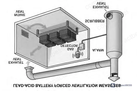
Tier 2 — Forced Ventilation with Gas Treatment (Secondary Protection)
Mechanical ventilation replaces passive airflow with a controlled directional circuit: dedicated intake louvers, outlet ducting connected to an alkali-spray scrubbing tower (喷淋塔) that neutralizes HF and other acidic off-gases before atmospheric discharge. An inline real-time harmful gas monitor continuously tracks aerosol concentration; when readings approach the alarm threshold, the system triggers automated response — not a delayed manual check.
This tier specifically addresses the failure mode that passive ventilation cannot resolve: episodic gas concentration spikes from partially degraded cells that don’t correlate with time-of-day or ambient temperature in a predictable pattern. The monitoring data showed “slight exceedance fluctuations” in airborne gas content under traditional conditions — a phrase that translates operationally to unpredictable compliance violations.
Tier 3 — Emergency Collection (Terminal Protection)
The emergency sump is sized to the maximum electrolyte volume of a single battery module — not an average, and not a theoretical minimum. For minor spills, sodium bicarbonate (NaHCO₃) neutralization is the standard cleanup protocol. For large-volume releases, the sump intercepts the flow before surface runoff carries contamination off-site. Dry powder extinguishers are co-located in this zone for simultaneous battery short-circuit or fire scenarios.
This tier’s function is specifically to remain operational when Tiers 1 and 2 have partially failed — the closed-chain logic means the system doesn’t rely on perfect upstream performance.
Industry observation: most procurement teams don’t realize that IEC 62619 (secondary cells and batteries for stationary applications — safety requirements) was revised to increase emphasis on end-of-life and decommissioning procedures, not just operational safety. The gap between what IEC 62619 requires and what many existing storage facilities actually provide is where the liability sits.
Practical Guidance for Buyers #
If you are specifying, procuring, or auditing a battery disposal or decommissioning service — whether for LFP packs, ternary lithium modules, or mixed chemistry BESS systems — the three-tier framework described here should be your minimum baseline, not a premium option.
Start with the liner specification. A permeability coefficient of 1×10⁻¹² cm/s (HDPE + anti-seepage concrete dual-layer) is measurable and verifiable. If a supplier can’t provide this in writing, the facility is likely operating on legacy single-layer clay infrastructure — which the field data above shows consistently breaches national environmental limits.
The ventilation system is where qualified suppliers most visibly separate from unqualified ones. Passive ventilation is not compliant for LFP or ternary cell storage under GB 18597–2023. Ask specifically whether the exhaust ducting routes to an alkali-spray scrubbing tower, and whether the gas monitoring system triggers automated ventilation response or only passive alarm. The difference matters during off-hours cell degradation events.
Honestly, most buyers over-specify cell-level chemistry requirements in their RFQ documents and under-specify disposal chain requirements entirely. In our experience connecting global OEM buyers and energy storage integrators with verified Chinese manufacturers at CompactBESS, the disposal and containment question is one of the first things a serious technical buyer raises — and the answer reveals more about a supplier’s operational maturity than any certification document alone.
For LFP cell sourcing or pack enclosure and IP rating evaluation, containment infrastructure at end-of-life should be part of your supplier audit checklist from the first sample evaluation.
Need help identifying qualified suppliers for decommissioned battery storage and disposal compliance? Talk to our sourcing team →
Supplier Qualification Questions #
- What is the permeability coefficient specification for your battery storage floor system — specifically, can you confirm dual-layer HDPE membrane plus anti-seepage concrete achieving 1×10⁻¹² cm/s or below, and provide the third-party test report?
- What is the minimum berm height around your battery storage containment zone, and does the floor gradient meet or exceed 2% toward an emergency collection sump?
- Does your exhaust ventilation system route to an alkali-spray scrubbing tower for HF and acidic off-gas neutralization, or does it discharge directly — and can you provide the scrubber maintenance and performance log?
- What real-time monitoring instruments are installed for airborne harmful gas concentration, what is the alarm threshold relative to the GB 3095–2012 standard limit of 1.00 mg/m³, and does the alarm trigger automatic ventilation response or manual-only notification?
- How is your emergency collection sump volume calculated — is it sized to the maximum single-module electrolyte volume, and what is the documented neutralization protocol (NaHCO₃ or equivalent) for leachate treatment post-collection?
Sourcing Checklist #
- [ ] Dual-layer floor system confirmed: HDPE impermeable membrane + anti-seepage concrete, with documented permeability coefficient ≤1×10⁻¹² cm/s
- [ ] Containment berm height verified at minimum 15 cm around all battery storage zones
- [ ] Floor gradient confirmed at ≥2% directing liquid flow toward emergency collection sump
- [ ] Forced mechanical ventilation system present — not passive/natural ventilation only — with exhaust routed to alkali-spray scrubbing tower
- [ ] Real-time online gas monitoring installed with alarm threshold set at or below GB 3095–2012 limit of 1.00 mg/m³ for airborne harmful gas concentration
- [ ] Emergency collection sump capacity documented as ≥ maximum single-unit electrolyte volume; NaHCO₃ or equivalent neutralization protocol in place
- [ ] Defective/damaged cells stored in dedicated segregated zone with drip-containment pallets, per GB 18597–2023 hazardous waste storage requirements
- [ ] Post-implementation monitoring data available showing soil hazardous substance content <80.00 mg/kg and leachate contamination <0.10 mg/L against GB 36600–2018 and GB 18597–2023 limits
Key Specifications Table #
| Parameter | Recommended Value | Verification Method |
|---|---|---|
| Floor system permeability coefficient | ≤1×10⁻¹² cm/s (HDPE + anti-seepage concrete dual-layer) | Third-party permeability test report; on-site liner inspection |
| Containment berm height | ≥15 cm | Physical measurement during site audit |
| Floor drainage gradient | ≥2% toward emergency sump | Survey measurement or construction documentation |
| Soil hazardous substance content (post-implementation) | <80.00 mg/kg | Soil sampling against GB 36600–2018 |
| Leachate hazardous substance content | <0.10 mg/L | Leachate sampling and lab analysis against GB 18597–2023 |
| Water body COD | <20.00 mg/L | Surface water sampling against GB 3838–2002 |
| Airborne harmful gas concentration | <1.00 mg/m³ | Inline real-time gas monitor; alarm threshold at ≤1.00 mg/m³ per GB 3095–2012 |
Can’t find a supplier meeting these specs? Submit your requirements and we’ll match you within 48 hours.
Frequently Asked Questions #
Q1: Why do LFP batteries — generally considered safer than ternary lithium — still require forced ventilation and multi-tier containment in storage?
LFP cells contain carbonate-based electrolyte solvents and LiPF₆ lithium salt regardless of cathode chemistry. Under long-term storage conditions, especially for partially degraded or physically damaged cells, electrolyte vapor off-gassing and leachate seepage are active processes. The lower thermal runaway risk of LFP compared to NMC or NCA does not eliminate the electrolyte migration pathway — it only changes the thermal trigger threshold. Both chemistries require equivalent containment infrastructure.
Q2: What does a permeability coefficient of 1×10⁻¹² cm/s actually mean in practical terms?
It means the liner system is essentially impermeable on any operationally relevant timescale. For comparison, standard compacted clay liners used in legacy battery warehouses typically achieve around 1×10⁻⁷ cm/s — five orders of magnitude more permeable. The difference translates directly into whether electrolyte solvents and lithium salts reach subfloor soil and groundwater within months or remain contained over the facility’s operating life.
Q3: Is sodium bicarbonate (NaHCO₃) neutralization sufficient for lithium battery electrolyte spills?
For minor spills involving carbonate-based electrolyte solvents and LiPF₆, NaHCO₃ neutralization is the standard first-response protocol because it addresses the acidic decomposition products (including HF precursors) without generating secondary hazardous byproducts. Large-volume releases require professional hazmat containment and may involve additional treatment steps depending on the specific electrolyte formulation and contamination volume.
Q4: How does the three-tier framework handle a simultaneous electrolyte leak and fire event?
The framework co-locates fire suppression assets — dry sand boxes and Class D or dry powder extinguishers — within both the primary containment zone and the emergency collection area. If battery short-circuit accompanies electrolyte release, dry powder or sand coverage is the immediate response to isolate the thermal event, while the sump system continues to intercept liquid flow. The IEC 62619 safety standard and UN 38.3 transport certification both address thermal event containment requirements that apply to stored as well as transported cells.
Q5: At what point in the procurement process should disposal and containment requirements be specified?
Before supplier approval — not after. Containment infrastructure is a capital investment that existing facilities either have or don’t. Retrofitting a warehouse to meet dual-layer liner, forced ventilation, and emergency sump requirements is disruptive and expensive. Qualifying a supplier’s disposal capability at the RFQ stage, using the specific numeric thresholds in this article, is the only way to avoid inheriting legacy compliance gaps after a supply relationship is already established.
Published by compactbess.com Technical Team | Request a sourcing quote
Data source: Environmental Risk Prevention and Control Strategies for Solid Waste Disposal in Electrochemical Energy Storage Systems, H. Zhang et al., Journal of the Electrochemical Society, 2024


