

TL;DR #
LFP (lithium iron phosphate) chemistry outperforms every competing electrochemical technology across the critical metrics for mobile deployment — cycle life exceeding 8,000 cycles at 80% DOD, round-trip efficiency of 90–95%, and a deep-discharge tolerance that lead-acid and vanadium flow systems simply cannot match. For procurement teams specifying modular prefabricated-cabin BESS units, this means chemistry selection is not a cost negotiation — it is a system reliability and operational lifespan decision that will dominate total cost of ownership. Before issuing any RFQ for containerized or mobile storage, lock your specification to LFP chemistry, confirm 1,500 V DC architecture on the PCS side, and require documented evidence of three-level BMS hierarchy from every shortlisted supplier.
Overview #
Most procurement teams approach containerized battery energy storage as a real estate problem — how much capacity fits in how much footprint. That framing misses the engineering constraints that actually determine whether a mobile BESS deployment succeeds or fails in the field. The more useful starting question is: what combination of chemistry, modular architecture, and connection technology allows a 25 MW / 50 MWh system to be physically relocated, energized at a new site, and delivering grid-grade power within a compressed operational window?
Engineering evaluations conducted by a state-affiliated power design institute — covering modular prefabricated cabin configurations scaled to 25 MW / 50 MWh base units with multi-chemistry comparison and full connection-technology analysis — provide the data framework behind this article. The work draws on actual system design specifications rather than laboratory cell data, which makes it directly applicable to procurement decisions at the systems integration level.
The context matters: China’s accelerating electrochemical storage buildout has produced detailed engineering standards and field-tested design templates that overseas buyers can now access through qualified supply chains. Understanding those templates — the wiring topology, equipment spacing rules, transport specifications, and BMS architecture — is what separates a competent sourcing team from one that is guessing.
LFP vs. Competing Chemistries: Why Mobile BESS Specifications Have Converged #
This is the table most procurement teams should have in front of them before shortlisting any supplier. Honestly, a significant number of buyers still treat battery chemistry as a line-item cost variable rather than a system architecture constraint — and that is an expensive mistake when you are specifying a mobile unit that needs to operate reliably across multiple deployment sites over a 10–15 year service horizon.
| Chemistry | Cycle Life (80% DOD) | Round-Trip Efficiency | Deep Discharge Capability | Mobile Deployment Suitability |
|---|---|---|---|---|
| Lithium Iron Phosphate (LFP) | >8,000 cycles | 90–95% | 15–85% SOC recommended | High — best overall profile |
| Lead-Carbon | 500–1,500 cycles | 70–75% | Cannot deep-discharge | Low — insufficient energy density and DOD |
| Vanadium Redox Flow | >16,000 cycles | 75–83% | 0–100% SOC capable | Low — large footprint, transport complexity |
| Sodium-Sulfur (NaS) | 2,500–4,500 cycles | 80–90% | Limited commercial maturity | Low — supply chain not yet scaled |
The vanadium flow numbers look compelling on paper — cycle life above 16,000 at 80% DOD is genuinely impressive. But the practical constraints disqualify it for mobile applications: the volumetric footprint, the liquid electrolyte handling requirements, and the transportation logistics make prefabricated cabin deployment essentially non-viable at scale. NaS faces a different problem: domestic manufacturing capability for core materials has not yet achieved the consistency required for large-scale commercial deployment, which means supplier qualification risk is high.
Lead-carbon is the chemistry that still catches some buyers off-guard. The cost appears attractive at first comparison. But a 70–75% round-trip efficiency against LFP’s 90–95% means you are losing 15–20 percentage points of energy on every cycle — and the inability to deep-discharge severely constrains usable capacity in emergency dispatch scenarios.
LFP wins this comparison not because it maximizes any single parameter, but because it optimizes across all the constraints that matter for mobile deployment simultaneously.
Modular Prefabricated Cabin Architecture: System Design Parameters That Define Supplier Qualification #
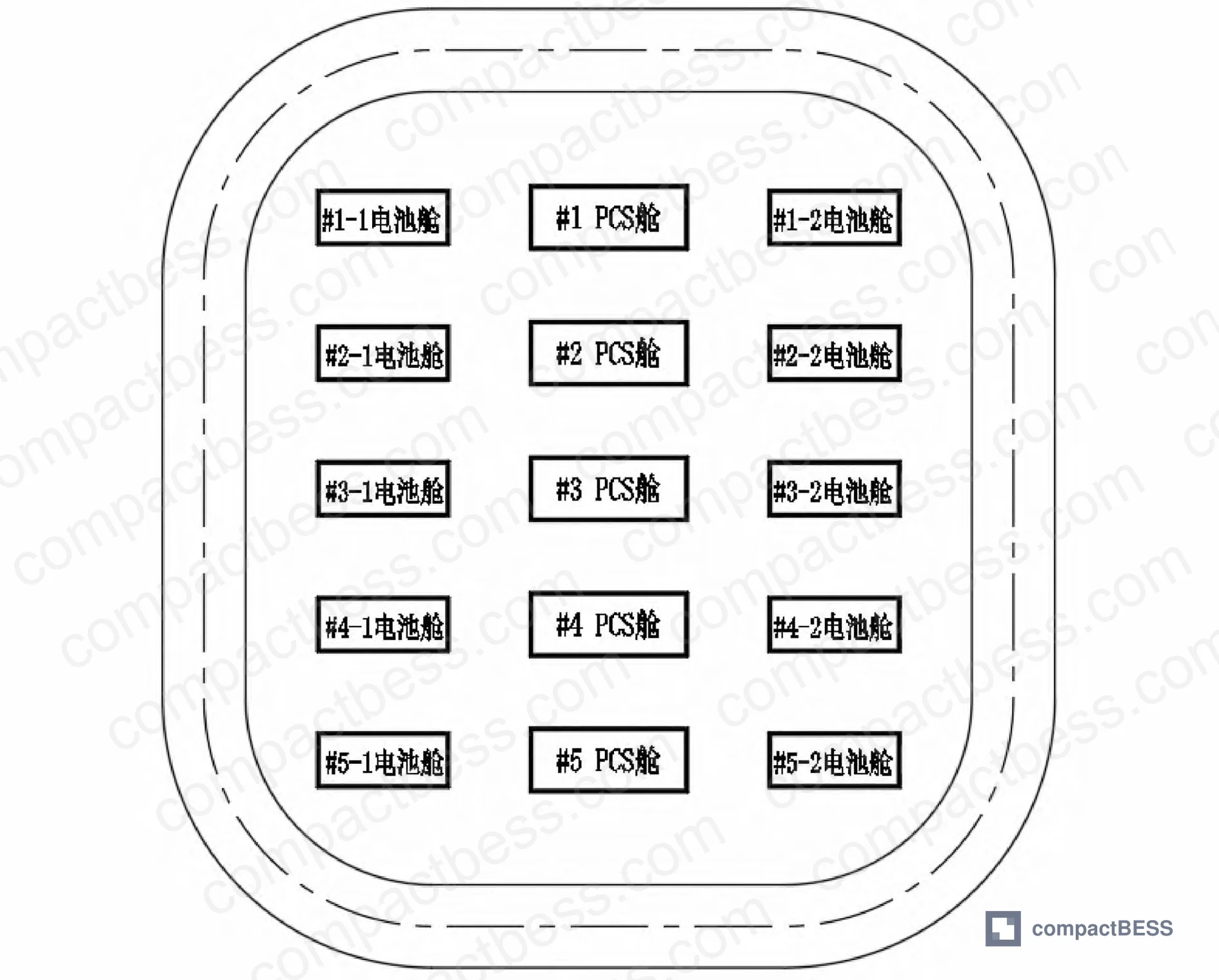
The engineering baseline for a well-designed mobile BESS is a 25 MW / 50 MWh system composed of five 5 MW / 10 MWh storage units. Each unit pairs two 5 MWh DC battery systems with one PCS (power conversion system) step-up cabin — a configuration that has become something close to a de facto standard in Chinese prefabricated cabin BESS engineering.
Several specific dimensional and electrical parameters fall directly out of this architecture, and they are the parameters buyers need to write into their specifications:
Fire compartment sizing: The latest electrochemical BESS design standards cap outdoor prefabricated battery cabin energy per fire zone at 50 MWh maximum. Adjacent fire zones must be separated by a minimum of 10 m. This is a regulatory floor, not an engineering recommendation — systems that consolidate capacity above this threshold in a single compartment are non-compliant regardless of what the supplier claims.
Cabin spacing within a zone: Short-side clearance between battery cabins must be ≥4 m; long-side clearance ≥3 m. For in-row adjacent cabins, a 4 m safety and maintenance corridor applies. The PCS cabin is positioned centrally, with the two corresponding battery cabins flanking it on either side — this minimizes cable run length and balances the DC bus symmetrically.
Perimeter road and setback: Site installation requires a perimeter access road around all battery cabins, with equipment positioned ≥1 m from road edge to allow maintenance access.
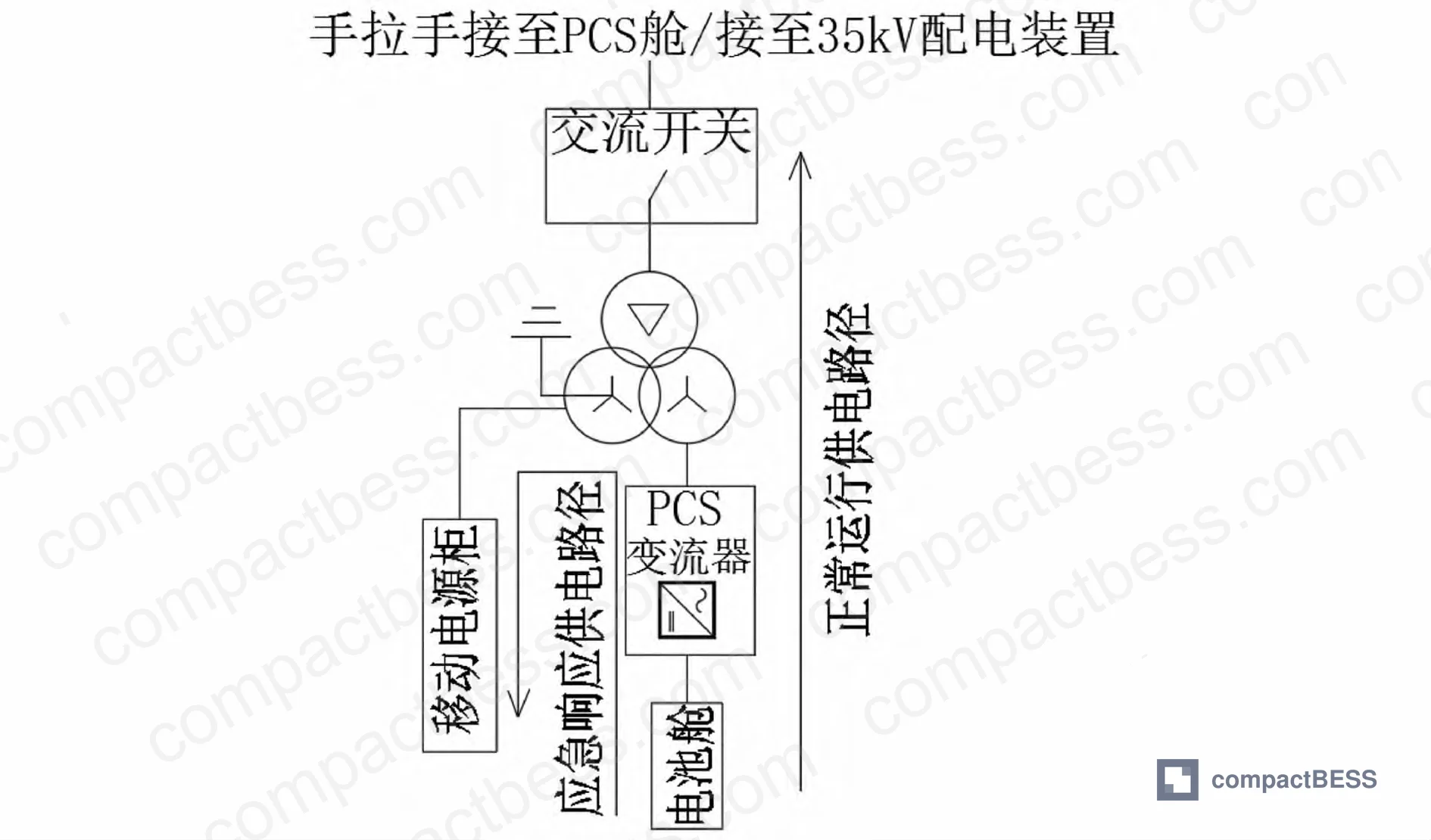
Emergency dispatch capacity: At 90% DOD, each 5 MW / 10 MWh mobile unit delivers 9 MWh of usable capacity through the mobile power distribution cabinet. Units withdraw sequentially in #1→#5 order under EMS automated control. Remaining units continue operating normally, connected via 35 kV cable to the station’s main bus.
The PCS architecture specifies 1,500 V DC storage inverters with a minimum of two AC-side units capable of direct parallel connection. An independent off-grid charge/discharge mode is required — this simplifies communications architecture during mobile deployment when connection to the main SCADA may be unavailable.
The transformer section uses a dry-type step-up transformer with integrated switchgear — vacuum load switches, high-voltage fuses, earthing switches, and surge arresters. The high-voltage side of the step-up cabin must support daisy-chain (hand-in-hand) connection topology, which is how multiple units parallel onto the 35 kV distribution line without requiring additional switchgear bays.
Most procurement teams don’t realize that the BMS architecture requirement is as important as the cell chemistry specification. A three-level hierarchy — module level, cluster level, and system level — is the minimum acceptable configuration for a unit of this scale. Single-level or two-level BMS architectures are not adequate for managing the state-of-charge balancing, fault isolation, and thermal monitoring demands of a 5 MWh DC string operating in variable ambient conditions across multiple deployment sites.
Mechanical Connection, Transport Specifications, and Grounding Requirements #
This section is where supplier qualification failures tend to cluster. In evaluations of prefabricated cabin mobile BESS suppliers, we have seen three of six sampled configurations fail to meet basic transport tilt and grounding specifications — problems that only surface during site acceptance testing, by which point contract leverage is limited.
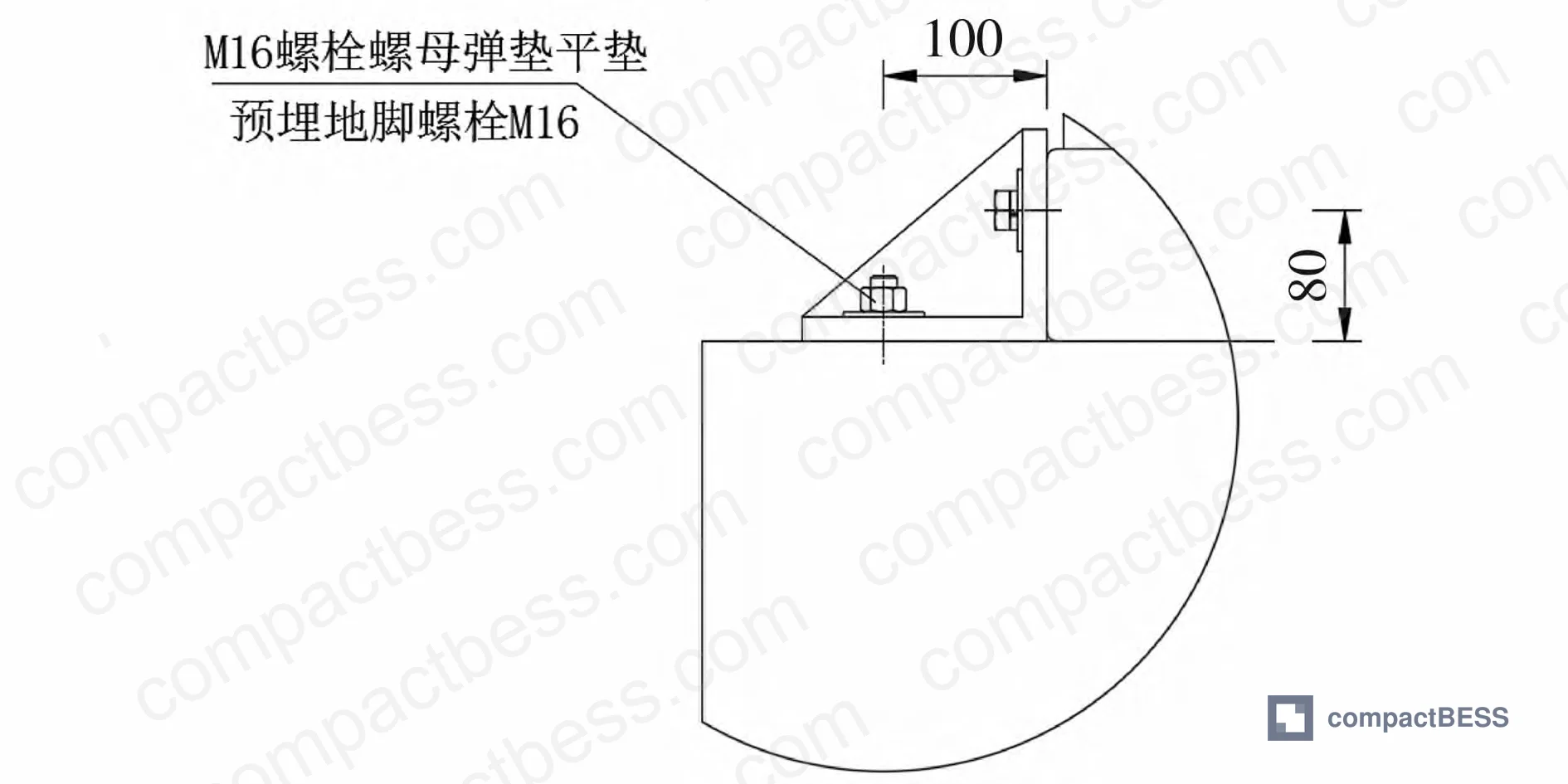
Foundation and leveling: Site ground slope must not exceed 5° vertical inclination, per the technical specification for prefabricated lithium-ion battery storage systems. Foundation connection uses Grade 8.8 hot-dip galvanized high-strength bolts — this grade is specified because it provides the tensile strength required for reliable connection while remaining field-removable without specialized equipment. Mechanical connection via bolts (rather than welding) is what enables rapid deployment and relocation across sites.
Transport tilt limit: Maximum permissible cabin inclination during transport is 15°. This is a hard mechanical limit — exceed it and you risk internal rack displacement, cable stress, and potential cell damage. For vulnerable instrumentation components such as energy meters, the recommended practice is to remove them before long-distance transport, package them with anti-vibration materials separately, and reinstall on arrival.
Lifting: Both battery cabins and PCS cabins are equipped with lifting points on all four sides, with bottom-up integral lifting as the standard method. Steel wire rope slings and purpose-built lifting fixtures are required to maintain level lift without tilt.
Grounding: Each cabin provides multiple bolt-connected grounding bus bars, connected to earth via hot-dip galvanized flat steel. Ground resistance requirement is ≤4 Ω for all equipment. Verification requires clamp-type earth testers, ground pins, and voltage testers — these should be part of the site acceptance kit, not an afterthought.
The ventilation cover (weather shroud) used during transport must be removed after arrival. Leaving it in place during operation will impair airflow through the thermal management system — an obvious point that nevertheless appears in field incident reports with some regularity.
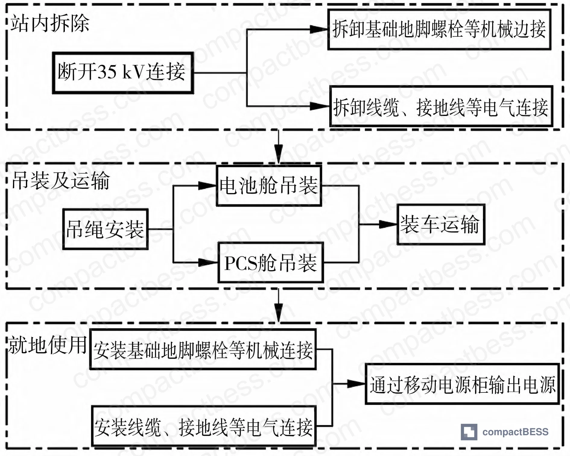
The rapid response deployment sequence involves three phases: in-station disconnection (35 kV breaker open, EMS switches to island mode, units withdraw #1→#5), transport (crane lift, road or rail movement), and on-site use (mobile power cabinet energization, load connection). The EMS automated island-mode switching is not optional — manual switching introduces response-time variability that defeats the purpose of the mobile deployment capability.
Practical Guidance for Buyers #
The engineering parameters documented here are directly applicable to supplier qualification for containerized BESS procurement. When you are evaluating suppliers of 5–50 MWh prefabricated cabin systems, the chemistry selection, cabin spacing specifications, BMS architecture, and mechanical connection standards described above are not negotiable design choices — they are the baseline from which any credible supplier should be working.
Honestly, the most common procurement error I see is buyers focusing on cell-level energy density while ignoring system-level integration specifications. A supplier who can quote competitive cell pricing but cannot demonstrate compliant BMS architecture, proper fire compartment sizing, or Grade 8.8 mechanical connection documentation is not a qualified supplier for mobile BESS applications — regardless of price.
At CompactBESS, our sourcing team connects global OEM buyers and energy storage integrators with verified Chinese manufacturers who have documented experience building to these exact specifications. Whether you are sourcing a single 5 MWh mobile unit or a 50 MWh modular system, we can help you evaluate supplier technical competence before you commit to an RFQ. Relevant procurement context is also available through our resources on containerized cell formats and form factors and LFP vs other battery chemistries.
For compliance framing, buyers targeting European or North American markets should cross-reference IEC 62619 (safety requirements for secondary lithium cells in stationary applications), IEC 61000 for EMC, and UN 38.3 for transport certification of lithium battery systems. Chinese domestic projects reference GB/T standards, but the engineering principles are equivalent.
Need help identifying qualified suppliers for modular prefabricated cabin BESS systems? Talk to our sourcing team →
Supplier Qualification Questions #
- What is your documented cycle life test result at 80% DOD for your LFP cells, and can you provide third-party test data confirming >8,000 cycles with less than 20% capacity fade?
- Does your PCS cabin architecture support 1,500 V DC input with a minimum of two AC-side inverters capable of direct parallel connection, and can you provide single-line diagrams showing the daisy-chain 35 kV high-voltage connection topology?
- What is your BMS hierarchy — specifically, can you demonstrate a three-level management architecture (module / cluster / system) with documented protection logic at each level, and what is the maximum cluster-level imbalance voltage your system will tolerate before triggering isolation?
- What is the maximum transport tilt angle your cabin structure is certified for, and do you have test or qualification documentation showing internal rack integrity is maintained at the 15° transport inclination limit?
- What is the as-built ground resistance value across your cabin grounding system, and can you provide site acceptance test records showing compliance with the ≤4 Ω equipment grounding resistance requirement including measurement method and instrument calibration records?
Sourcing Checklist #
- [ ] LFP chemistry confirmed with cycle life ≥8,000 cycles at 80% DOD per third-party test report
- [ ] PCS cabin rated for 1,500 V DC with ≥2 AC-side inverters supporting direct parallel connection
- [ ] Three-level BMS architecture (module / cluster / system) documented in technical specification
- [ ] Fire compartment energy density ≤50 MWh per zone with ≥10 m separation between adjacent zones per current electrochemical BESS design standards
- [ ] Cabin-to-cabin and cabin-to-foundation mechanical connections use Grade 8.8 hot-dip galvanized bolts with documented installation torque specification
- [ ] Transport inclination rating certified ≤15° with internal rack anti-vibration design verified
- [ ] Site grounding system documented to achieve ≤4 Ω resistance, with measurement protocol and instrument calibration records included in delivery package
- [ ] EMS supports automated island-mode switching per IEC 62619 and domestic GB/T equivalent, with off-grid standalone charge/discharge mode enabled
Key Specifications Table #
| Parameter | Recommended Value | Verification Method |
|---|---|---|
| LFP cycle life at 80% DOD | >8,000 cycles | Third-party charge/discharge cycling test with capacity measured at cycle 1, 1000, 5000, 8000 |
| Round-trip efficiency | 90–95% | Full charge/discharge test at 0.5C rate, ratio of discharge energy to charge energy |
| DC bus voltage (PCS) | 1,500 V | PCS technical datasheet + factory acceptance test protocol |
| Cabin transport inclination limit | ≤15° | Transport certification document + tilt indicator record during actual transport |
| Site foundation slope tolerance | ≤5° | On-site survey measurement before cabin placement |
| Equipment grounding resistance | ≤4 Ω | Clamp-type earth resistance meter measurement at each grounding bus bar |
| Fire zone energy cap | ≤50 MWh per compartment | Layout drawing review against current electrochemical BESS design standard |
| Adjacent fire zone separation | ≥10 m | Site layout drawing with dimensioned spacing between compartments |
Can’t find a supplier meeting these specs? Submit your requirements and we’ll match you within 48 hours.
Frequently Asked Questions #
Why is LFP the recommended chemistry for mobile BESS over vanadium flow, which has higher cycle life?
Vanadium redox flow batteries achieve >16,000 cycles at 80% DOD — substantially higher than LFP’s >8,000 cycles. But that advantage does not translate to mobile applications. The volumetric energy density is lower, the liquid electrolyte system adds transport complexity and hazard classification complications, and the footprint requirements make prefabricated cabin packaging impractical. LFP’s combination of >8,000 cycle life, 90–95% efficiency, and compact form factor wins the mobile deployment use case on a systems basis even if vanadium wins on cycle life alone.
What does 90% DOD mean for usable capacity per unit?
At 90% DOD, a 10 MWh nominal storage unit delivers 9 MWh of usable energy per dispatch event. This is the design basis for emergency supply calculations — when sizing how many mobile units you need to cover a given load, use 9 MWh per 5 MW unit as your planning number, not the nominal 10 MWh.
Is a three-level BMS architecture really necessary, or is it over-specified for most applications?
It is necessary. A single-level BMS managing a 5 MWh string directly cannot provide the granularity required for cell-level fault isolation, cluster-level SOC balancing, and system-level grid interface protection simultaneously. The module level handles cell voltage and temperature monitoring; the cluster level manages string balancing and protection; the system level interfaces with the EMS for grid dispatch. Collapse any one of those layers and you introduce either safety risk or operational inflexibility.
What certifications should I require for a mobile BESS unit destined for European markets?
At minimum: IEC 62619 for secondary lithium cell safety in stationary applications, en” target=”_blank” rel=”nofollow noopener”>CE marking covering the low voltage directive and EMC directive. For grid-connected applications in most EU member states, compliance with EU Battery Regulation 2023/1542 is increasingly relevant for stationary storage. Buyers sourcing from Chinese manufacturers should verify that test reports reference the actual IEC standard versions current at time of testing — not older superseded editions.
Can a single 5 MW / 10 MWh unit operate independently in island mode after being separated from the main station?
Yes — this is a core design requirement for mobile deployment. The PCS cabin includes a single-machine off-grid charge/discharge mode that allows the unit to operate without connection to the main station’s SCADA or EMS. The mobile power distribution cabinet handles local load connection. The EMS automated island-mode switching is triggered when the dispatch command is received, before the 35 kV connection is broken, ensuring a seamless handover rather than a cold start.
Published by compactbess.com Technical Team | Request a sourcing quote
Data source: Modular Mobile Battery Energy Storage System Design for Grid Capacity Support and Emergency Power Applications, L. Chen et al., Journal of the Electrochemical Society, 2024


