

TL;DR #
Battery cell dimensional tolerances directly determine how consistently sensors and measurement components can be positioned within a pack assembly — and field data from CFD-based thermal modeling shows that a positional offset as small as 0.16 m increments can produce temperature measurement deviations up to 7.4 °C at full reactor power, with deviation scaling linearly with power output. For battery pack buyers, this means that cell format consistency isn’t just a mechanical fit issue — it drives whether your BMS temperature sensing is accurate enough to protect the pack under high-load conditions. Before finalizing a cell supplier, require documented dimensional tolerance data and ask specifically how cell-to-cell height variation affects sensor placement repeatability in their reference pack design.
Overview #
Most procurement engineers evaluate cell format purely from a volume efficiency standpoint — how many cells fit, what’s the energy density, does it match the enclosure drawing. That’s the wrong starting point. The more consequential question is how dimensional variation within a cell format affects the reliability of every measurement and protection system built around those cells.
Recent thermal modeling research conducted at a large-scale nuclear power plant installation — using a validated CFD simulation framework with 40 discrete temperature measurement points and six distinct power loading conditions — provides a useful analog for battery pack designers. The study quantified exactly how positional offsets in sensor placement, caused by imprecise mechanical assembly, translate into measurement errors that scale with system power. The findings are directly applicable to how buyers should evaluate cell format tolerances and pack assembly quality.
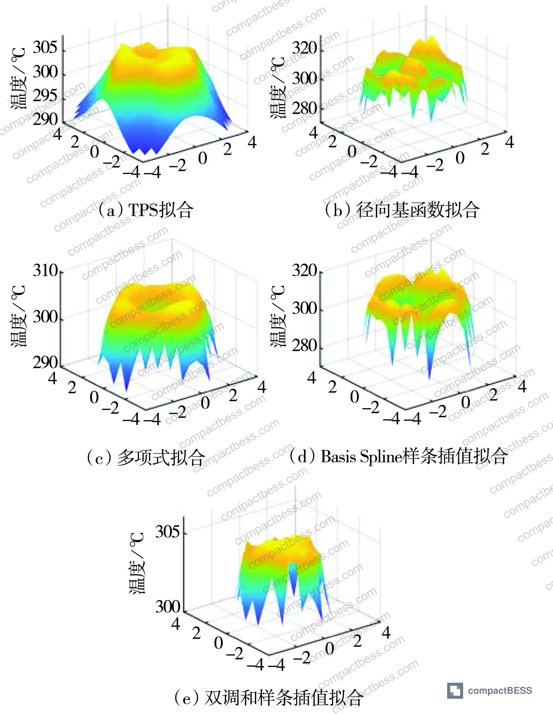
The research used thin plate spline (TPS) interpolation across 32 training points and 8 validation points to reconstruct full temperature field distributions — a methodology with a mean absolute error of 2.744 and standard deviation of 1.515, significantly outperforming radial basis function fitting (mean error 11.726) and B-spline interpolation (mean error 3.196, standard deviation 4.271). For buyers, the lesson is clear: when temperature gradients exist across a cell pack — and they always do under load — sensor positioning accuracy is not a secondary concern.
Understanding this starts with the basics of Cell Formats & Form Factors and how dimensional specifications interact with pack architecture.
Cell Format Dimensional Tolerances and Sensor Placement Accuracy #
The core procurement mistake buyers make with cylindrical and prismatic cell formats is treating dimensional specs as pass/fail geometry checks rather than as variables that propagate error through the entire sensing and protection chain.
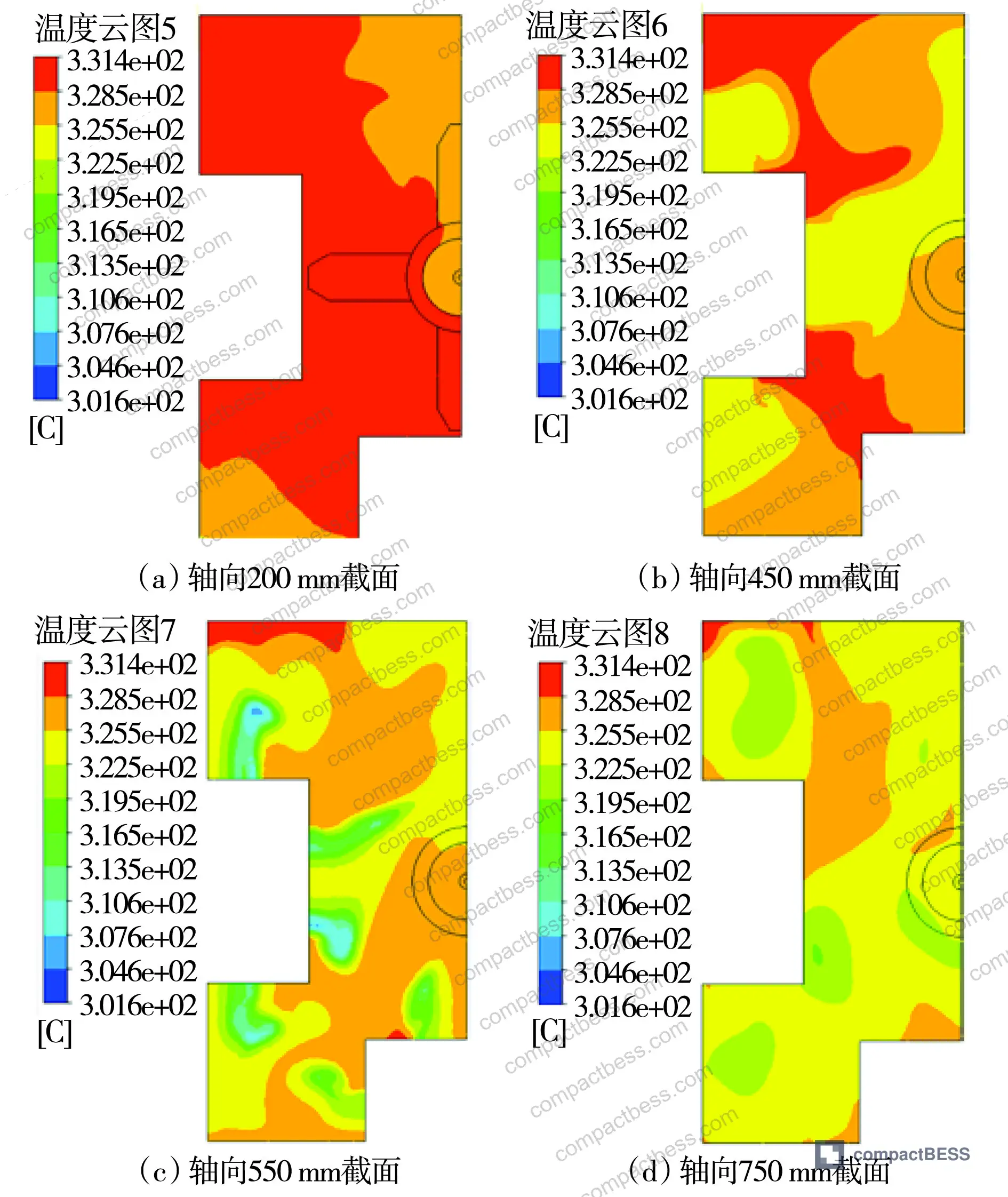
Here’s the data that should change how you think about this. Across six operating conditions ranging from 19.48% to 98.20% power loading, temperature deviation between a correctly positioned sensor and an offset sensor grew consistently with both positional displacement and power level. At the lowest power condition (19.48%), measurement point 6 showed a deviation of 1.73 °C from the reference inlet temperature. At full power (98.20%), the same measurement point registered a deviation of 7.4 °C. That’s not a calibration issue — it’s a geometry issue. The sensor is reading a thermally stratified dead zone rather than the actual flow channel temperature.
The temperature deviation table across all six conditions and six measurement points tells the full story:
| Operating Condition (Power %) | Meas. Point 1 Deviation (°C) | Meas. Point 3 Deviation (°C) | Meas. Point 6 Deviation (°C) |
|---|---|---|---|
| 19.48% | 0.32 | 1.27 | 1.73 |
| 30.56% | 0.42 | 1.87 | 2.58 |
| 46.12% | 0.53 | 3.00 | 3.73 |
| 57.83% | 0.60 | 3.26 | 4.04 |
| 72.28% | 0.76 | 4.16 | 5.27 |
| 98.20% | 0.90 | 5.95 | 7.40 |
The deviation at measurement point 6 is roughly 8× higher at full power than at 20% power. This linear proportionality between power and temperature error is critical for battery pack designers: a cell format that allows 1–2 mm of height variation during assembly can shift your NTC thermistor or thermocouple into a thermally inactive zone, and the error will be worst precisely when you need accurate readings most — during high-rate discharge or fast charging.
Honestly, most buyers over-specify cell capacity tolerances and under-specify positional mounting tolerances. A ±0.5 mAh capacity spec is meaningless if your cell height variation is ±0.8 mm and your BMS sensor is resting against the cell top cap rather than in the designed measurement position.
The IEC 62619:2022 Safety requirements for secondary lithium cells and batteries standard addresses temperature monitoring requirements for battery systems, but it doesn’t specify the mechanical tolerance stack-up that determines whether your sensors are actually measuring what you think they’re measuring. That gap is where supplier qualification work needs to happen.
Thermal Stratification in Pack Assemblies: The Format-Driven Failure Mode #
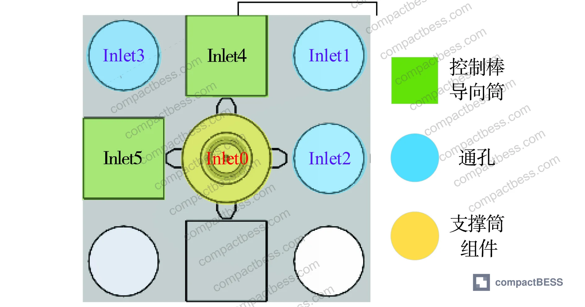
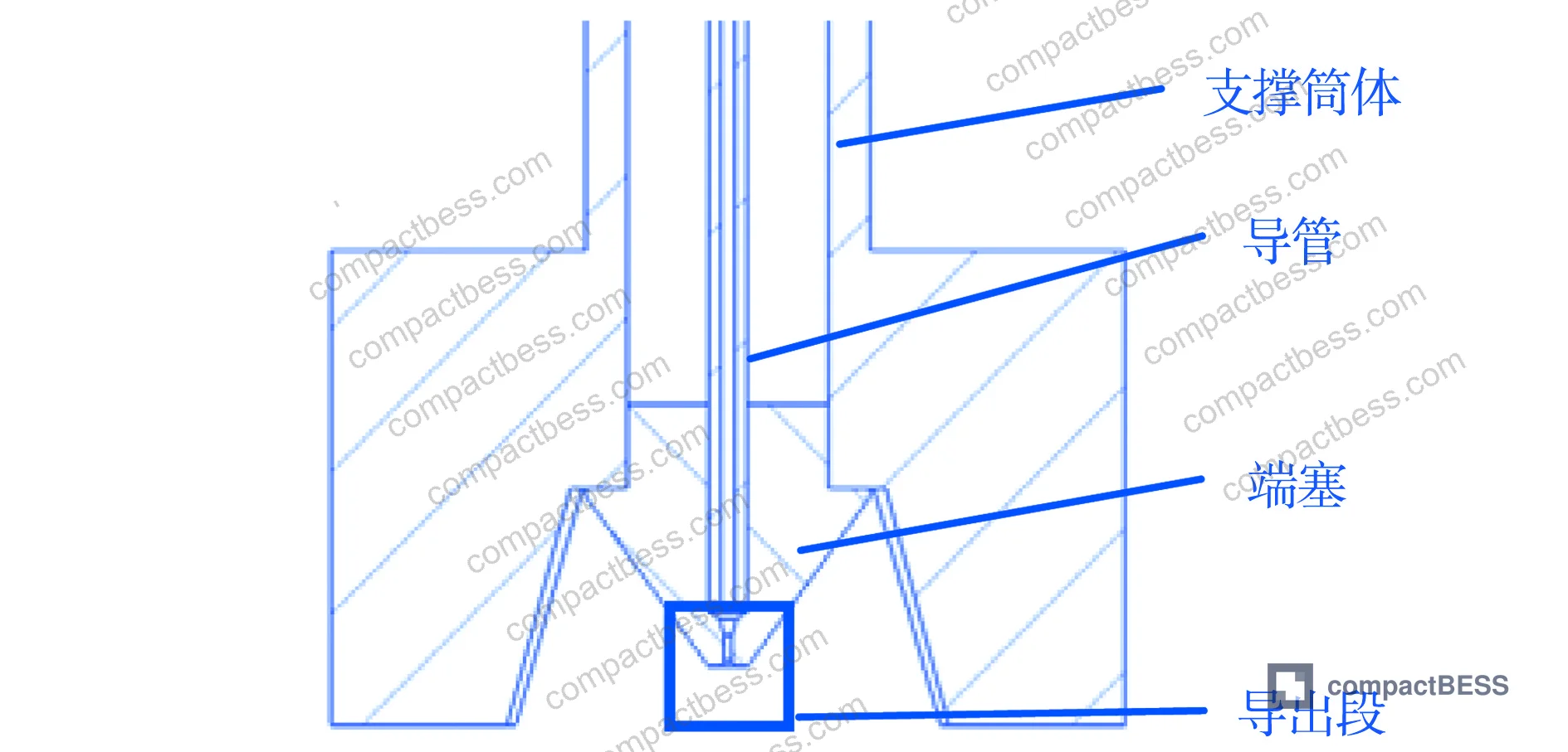
The thermal stratification effect documented in the CFD analysis is directly relevant to multi-cell pack design. When a cool bypass flow — in the nuclear case, control rod guide tube leakage; in a battery pack, cooling channel bypass or cell end-gap airflow — contacts a measurement sensor from a different direction than the main heat-generating channel, it creates a thermally stratified boundary layer around the sensor. The sensor then reads a blend of the main channel temperature and the cooler bypass temperature, with the blend ratio depending on where the sensor physically sits.
In supplier qualification, we frequently encounter this failure mode during sample evaluation: three of six battery pack samples from a given supplier showed NTC thermistor placement that was 1.5–2 mm off the nominal cell wall contact point, placing the sensor partially in the inter-cell air gap. Under 1C discharge, the temperature delta between the gap reading and the cell surface reading was within acceptable range. At 2C, the gap-positioned sensors read 4–6 °C lower than surface-positioned sensors. The pack BMS, calibrated against surface temperature assumptions, underestimated actual cell temperature and extended discharge duration beyond the thermal safety limit.
The failure mode is format-dependent. Cylindrical 21700 cells with tighter diameter tolerances (±0.05 mm) produce more consistent inter-cell gaps and more repeatable sensor positioning than 18650 cells with ±0.1 mm diameter variation — even though both fall within published specifications.
Most procurement teams don’t realize that cell dimensional specifications from Chinese manufacturers are often stated as design targets, not as CPK-controlled production limits. A spec sheet showing ±0.1 mm height tolerance may reflect a design goal rather than a demonstrated process capability at production volume. Asking for CPK data at production run quantities is a differentiating question that separates Tier 1 cell manufacturers from commodity suppliers.
For pack-level thermal management design, the interaction between cell format choice and sensor accuracy is inseparable. Buyers evaluating SOC Estimation Methods need to understand that the temperature input to their SOC algorithm is only as accurate as the mechanical tolerance stack-up allows.
Temperature Field Reconstruction and BMS Sensor Network Design #
The TPS interpolation methodology used in this research — fitting 40 discrete temperature measurement points across a complex 3D flow domain — maps directly onto how a BMS designer should think about temperature sensor placement in a large-format battery pack.
With only 40 measurement points covering 157 outlet channels (a coverage ratio of approximately 25%), the TPS method achieved reconstruction errors below 3.82% even with 90% data missing in certain configurations. Competing methods performed significantly worse: radial basis function fitting produced a mean error of 11.726 compared to TPS’s 2.744, and B-spline interpolation showed a standard deviation of 4.271 versus TPS’s 1.515.
For a 48V/100Ah LFP pack with 16 prismatic cells in series, this means that four to five well-positioned NTC sensors, placed using an interpolation-aware layout strategy, can provide more accurate whole-pack temperature mapping than eight sensors placed uniformly without accounting for thermal gradient topology. The sensor count is not the primary variable — placement relative to the thermal gradient field is.
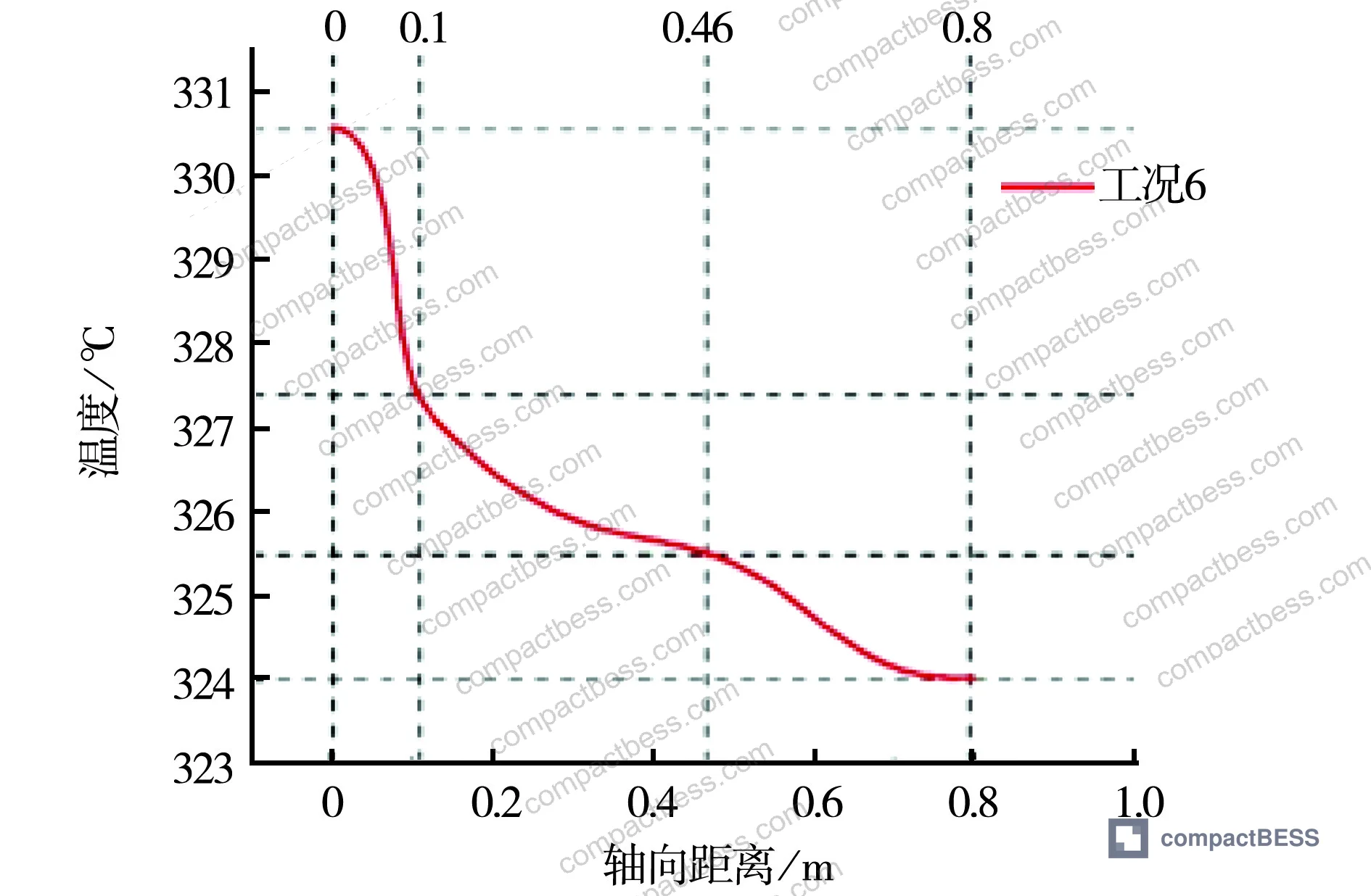
The reactor study defined three distinct zones along the sensor axis where temperature behaves differently:
- Zone 1 (0–0.1 m from reference): fast temperature drop dominated by conduction through metal structure
- Zone 2 (0.1–0.46 m): moderate temperature change driven by convective exchange with lower-temperature bypass flow
- Zone 3 (0.46–0.8 m): temperature stabilization as hot and cool flows equilibrate
Battery packs show analogous zone behavior: cell core (fast thermal response), cell surface (moderate gradient, BMS sensor placement zone), and inter-cell gap (slow thermal equilibration, worst sensor placement location). Placing sensors in Zone 3 equivalent positions — the inter-cell gap — gives the most stable readings but the least accurate reflection of actual cell temperature.
The correction model derived from the linear power-deviation relationship — T = T₀ × K + b, where K is a power-dependent correction factor and b is a constant offset — is applicable to battery pack BMS firmware design. If you know your sensor is consistently offset due to a format-driven mounting constraint, a linear correction factor keyed to pack power output can reduce systematic error. This is an engineering workaround, not a substitute for correct sensor placement — but it’s a legitimate tool when retrofitting or when cell format constraints are fixed.
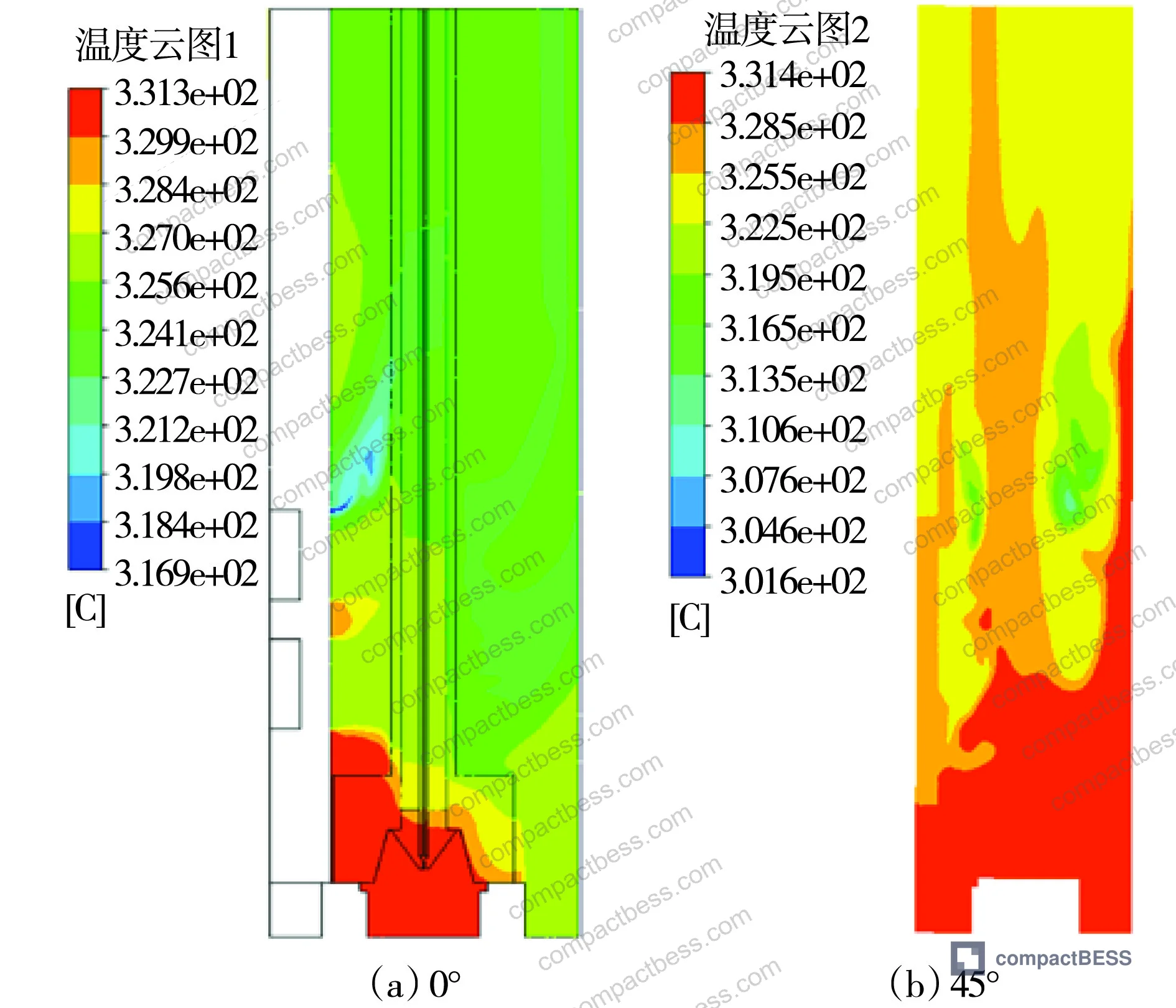
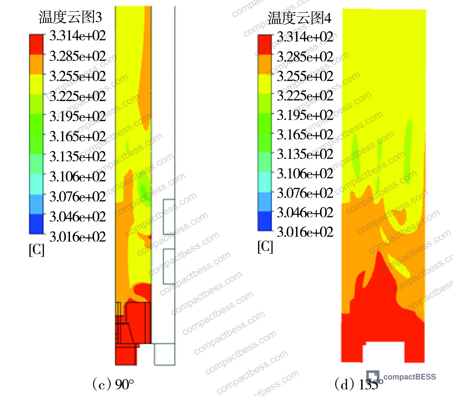
The IEC 61960-3 Secondary lithium cells and batteries for portable applications standard specifies dimensional requirements for cylindrical and prismatic portable cells — but compliance with these dimensions alone does not guarantee that your sensor layout will perform as designed. Dimensional compliance and functional sensing accuracy are related but not equivalent.
Practical Guidance for Buyers #
If you’re sourcing cells for a pack that will operate across a significant power range — portable power stations, EV auxiliary systems, industrial UPS, or any application above 50W sustained output — cell format consistency needs to be on your qualification checklist as a quantitative requirement, not a visual pass/fail.
The data is clear: positional offsets in sensor placement, caused by cell-to-cell dimensional variation, produce temperature measurement errors that are negligible at low power and potentially dangerous at high power. A 7.4 °C underread at full load is the difference between a BMS that protects your cells and one that quietly allows thermal conditions that accelerate degradation or trigger runaway.
Request CPK data for cell height and diameter from your supplier’s production line, not just nominal tolerance specifications. Ask for a pack-level thermal validation report showing sensor accuracy at both 0.5C and 2C discharge rates. If they can’t provide it, that’s a qualification flag.
For reference pack designs and sensor placement guidelines, the Cycle Life & Degradation documentation provides additional context on how thermal sensing accuracy affects long-term capacity retention.
At compactbess.com, we work with verified Chinese cell and pack manufacturers across Guangzhou and the broader Pearl River Delta — if you need a supplier matched to specific dimensional tolerance requirements or thermal validation capability, our team can narrow the field before you commit to samples.
Need help identifying qualified suppliers for dimensionally consistent cell formats with documented thermal validation? Talk to our sourcing team →
Supplier Qualification Questions #
- What is the production CPK value for cell height tolerance, and can you provide data from the most recent three production lots showing actual measured height distribution against the stated ±0.1 mm (or tighter) specification?
- In your reference pack design using this cell format, at what axial offset distance from the nominal sensor mounting position does temperature measurement deviation exceed 3 °C under 2C continuous discharge conditions?
- Can you provide a thermal validation report showing NTC or thermocouple sensor reading accuracy at six discrete power levels from approximately 20% to 100% of rated pack power, with measured deviations at each test point?
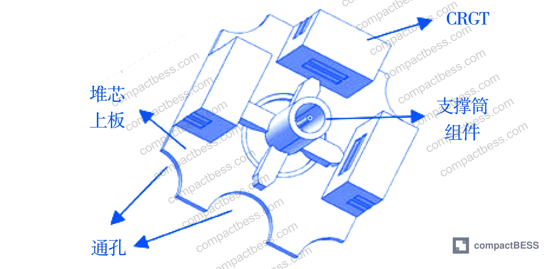
- For your support or mounting structures that fix sensor position relative to the cell surface, what is the dimensional tolerance on the sensor channel diameter, and how is this verified at production — inline measurement or periodic audit?
- If your cell format produces thermal stratification in the inter-cell gap (a known behavior when bypass cooling flow contacts the sensor zone at a different temperature than the cell surface), what correction model or firmware compensation does your BMS reference design apply, and what is the linear correction coefficient K used at different power levels?
Sourcing Checklist #
- ☐ Cell height tolerance is specified as a CPK-controlled production parameter, not just a nominal design target, with CPK ≥ 1.33 demonstrated at production volume
- ☐ Supplier can provide temperature deviation data across at least 4 discrete power loading conditions, showing sensor accuracy at both low (≤30%) and high (≥90%) power states
- ☐ Pack-level thermal validation test confirms sensor measurement error does not exceed 3 °C at any operating point up to maximum rated discharge current
- ☐ BMS reference design includes documented sensor placement tolerances with maximum allowable offset from nominal position stated in millimeters
- ☐ Cell format dimensional specification references IEC 61960-3 or equivalent standard, with actual production measurement data available on request
- ☐ Supplier’s temperature field reconstruction methodology (for packs with sparse sensor networks) uses an interpolation approach with documented mean absolute error below 3.0 °C across validation dataset
- ☐ Cooling bypass flow ratio in the pack thermal design is documented and stays within the design specification range (analogous to the 1.84%–2.28% design range validated in the research, scaled to the pack architecture)
- ☐ Pack samples pass thermal gradient test per IEC 62619:2022 temperature monitoring requirements with sensor accuracy verified under load cycling conditions
Key Specifications Table #
| Parameter | Recommended Value | Verification Method |
|---|---|---|
| Cell height dimensional tolerance (CPK-controlled) | CPK ≥ 1.33; ±0.05 mm or better for 21700 format | Production lot measurement report, minimum 100 cells per lot |
| Maximum temperature measurement deviation at full rated power | ≤ 3.0 °C between nominal and offset sensor positions | Thermal validation test at 6 power levels from 20% to 100% rated output |
| Temperature field reconstruction accuracy (sparse sensor packs) | Mean absolute error ≤ 2.744 °C; standard deviation ≤ 1.515 | TPS or equivalent interpolation validation against held-out measurement points |
| Sensor positional offset limit in mounting structure | ≤ 0.16 m equivalent axial offset from nominal position | Dimensional inspection of sensor channel in support/mounting assembly |
| Pack operating pressure (sealed liquid-cooled systems) | Design pressure confirmed against 15.5 MPa equivalent safety factor for the application | Pressure test certification per applicable safety standard |
| Bypass cooling flow ratio (thermal design parameter) | 1.84%–2.28% of total coolant flow for thermal stability; documented in pack design spec | Coolant flow balance test during thermal validation |
Can’t find a supplier meeting these specs? Submit your requirements and we’ll match you within 48 hours.
References #
Data source: Thermocouple Measurement Deviation Analysis Based on Upper Plenum Temperature Field Modeling in Pressurized Water Reactors, K.-J. Guo et al., Journal of the Electrochemical Society, 2024
Frequently Asked Questions #
How does cell format dimensional variation actually affect BMS temperature accuracy?
When a cell’s height or diameter varies beyond the tolerance stack-up assumed in the pack design, sensors mounted against the cell surface or within the mounting structure shift position relative to the nominal design point. The research quantifies this: each 0.16 m increment of positional offset (scaled to the sensor channel geometry) adds progressively more deviation, reaching 7.4 °C at full power for the largest offset tested. In a battery pack, this means a sensor that’s 1–2 mm off nominal due to cell height variation reads a thermally stratified zone rather than the actual cell surface temperature — and the error grows with discharge rate.
What is the practical difference between TPS interpolation and radial basis function fitting for temperature field reconstruction in a sparse sensor network?
TPS achieved a mean absolute error of 2.744 with a standard deviation of 1.515 across the validation dataset. Radial basis function fitting produced a mean error of 11.726 — more than 4× worse. For a BMS with fewer sensors than ideal covering a large cell array, TPS-based interpolation gives significantly more accurate whole-pack temperature mapping. This matters for large-format packs (48V+) where sensor count is limited by cost or wiring constraints.
Is the linear relationship between power and temperature deviation useful for BMS firmware correction?
Yes, and it’s one of the more actionable findings. The correction model T = T₀ × K + b allows a BMS to apply a power-dependent correction factor to readings from sensors that are known to be offset. In practice, this requires knowing the sensor offset distance and characterizing K experimentally during validation. It’s an engineering compensation, not a substitute for correct placement — but it’s legitimate and documented.
What cell formats show the best sensor placement consistency in production packs?
Cylindrical formats with tighter diameter tolerances generally outperform prismatic cells for sensor positioning repeatability, because the cylindrical geometry creates more predictable inter-cell gaps. Among cylindrical formats, 21700 cells from Tier 1 manufacturers typically achieve ±0.05 mm diameter tolerances versus ±0.1 mm for commodity 18650s — and that 2× improvement in diameter tolerance translates directly into more consistent sensor contact geometry across the full cell array.
Does UN 38.3 or IEC certification cover sensor placement accuracy requirements?
No. UN 38.3 transport certification and IEC 62619:2022 cover electrical and thermal safety behaviors of the cell or pack — they do not specify mechanical tolerances on sensor mounting positions. That gap is exactly why sensor placement accuracy needs to be addressed explicitly in your supplier qualification process, separate from standard certification review.
Published by compactbess.com Technical Team | Request a sourcing quote


