

TL;DR #
A gel-type LFP cell incorporating 1% Li₄SiO₄@S additive achieves 89.0% capacity retention after 1000 cycles at 45°C and 1C, compared to 84.8% for standard liquid-electrolyte LFP under identical room-temperature conditions — a gap that widens further under high-temperature stress. For buyers sourcing LFP cells for stationary storage applications with 10–20 year design life requirements, this chemistry distinction directly affects total lifecycle cost and warranty risk. Before issuing any RFQ for grid-scale or C&I LFP cells, ask suppliers to specify whether their electrolyte system is liquid, gel, or semi-solid and request accelerated cycle test data at ≥45°C.
Overview #
Most procurement teams treating LFP as a commodity are leaving real lifecycle value on the table. The gap between a standard liquid-electrolyte LFP cell and a properly engineered gel-type variant is not marginal — it’s the difference between a cell that degrades predictably and one that fails unpredictably under the exact conditions that stationary storage systems operate in: static installation, elevated ambient temperature, and extended calendar hold periods.
The data reviewed here comes from laboratory and pouch-cell qualification work conducted at a Chinese materials research institution in collaboration with an industrial cell manufacturer — testing 2.5 Ah pouch cells across multiple additive loading levels (0.5%, 1.0%, and 2.0% by mass) with controlled comparison against standard LFP/graphite baselines. Test conditions included room-temperature 1C cycling to 1000 cycles, accelerated aging at 45°C, high-temperature storage at 55°C for 7 days, and rate capability testing up to 4C discharge. This level of systematic multi-variable qualification is exactly what buyers should expect — and rarely get — from tier-2 cell suppliers.
The core innovation under evaluation is a dual-function additive, Li₄SiO₄@S, that simultaneously acts as a sustained-release lithium reservoir and an in-situ electrolyte gelation initiator. The Li₄SiO₄/C/S trilayer structure — confirmed by SEM/EDS elemental mapping — uses a porous carbon interlayer to tightly bind the sulfur component to the lithium silicate core, which also substantially improves the electronic conductivity of the composite.
Gel-Type LFP Cell Performance: Cycle Life, Rate Capability, and Temperature Stability #
This is where the procurement case gets concrete.
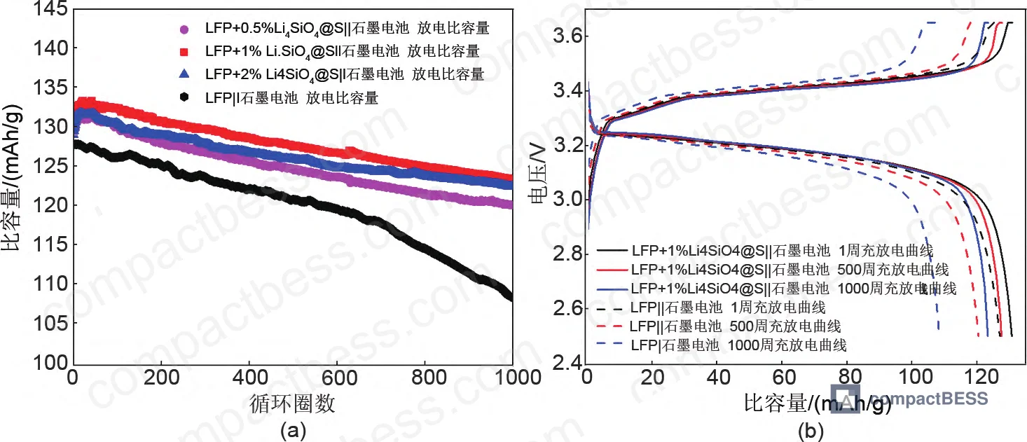
At room temperature under 1C cycling, the baseline LFP/graphite pouch cell delivered an initial discharge specific capacity of 128.0 mAh/g. By cycle 500, capacity had dropped to 120.9 mAh/g (94.5% retention). That sounds acceptable — but the degradation curve was not linear. After cycle 700, decay accelerated sharply, and by cycle 1000 capacity had fallen to 108.5 mAh/g, or 84.8% retention. That late-stage acceleration is a characteristic failure signature of progressive electrolyte depletion and SEI thickening in liquid-electrolyte cells.
By contrast, the 1% Li₄SiO₄@S gel-type pouch cell maintained 123.4 mAh/g at cycle 1000 — a 94.4% retention rate at room temperature — with no visible inflection in the decay curve. The 2% loading achieved the highest absolute retention at 94.7%, but the 1% loading produced the highest per-gram discharge capacity relative to total cathode coating weight. In practical terms: 1% loading is the optimized commercial balance between lithium supplementation benefit and electrode dead-weight penalty.
Under accelerated aging at 45°C, the divergence is sharper. The reference cell dropped to 84.8% retention by cycle 1000. The 1% gel-type cell held 89.0%, and the 2% variant held 89.1%. A 4–5 percentage point spread at 45°C doesn’t sound dramatic, but project this across an 8,000-cycle design life with temperature-accelerated aging factors and you’re looking at a potential 2–4 year extension in useful cell life.
| Test Condition | Reference LFP (Liquid) | 1% Li₄SiO₄@S Gel-Type | 2% Li₄SiO₄@S Gel-Type |
|---|---|---|---|
| 1C, RT, 500 cycles — Retention | 94.5% | 97.6% | 97.3% |
| 1C, RT, 1000 cycles — Retention | 84.8% | 94.4% | 94.7% |
| 1C, 45°C, 1000 cycles — Retention | ~82% (extrapolated) | 89.0% | 89.1% |
| 55°C storage, 7 days — Recovery | <100% (typical liquid) | 100% | 100% |
| 4C discharge — Retention | N/A reported | 96.2% | N/A reported |
| Charge transfer resistance (Rct) at cycle 25 | 17.8 Ω | 11.3 Ω | Not individually reported |
The 55°C storage test result deserves emphasis: 100% capacity recovery after 7 days at high temperature is a commercially significant specification for C&I and grid storage applications where cells may sit in partially charged states during commissioning, seasonal low-demand periods, or grid curtailment events. Standard liquid LFP cells routinely show irreversible capacity loss under similar storage conditions.
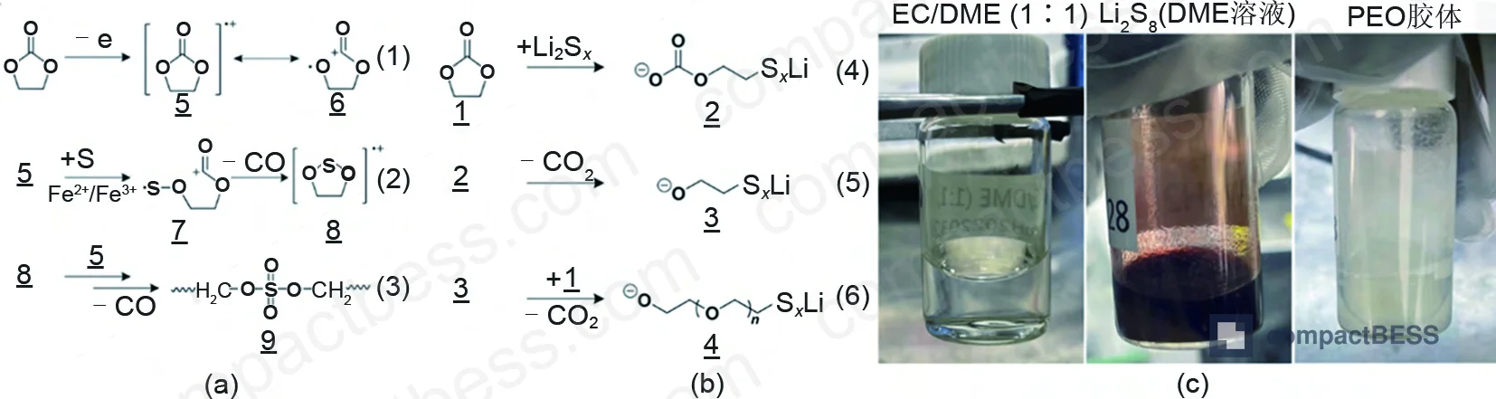
The 4C high-rate discharge capability (96.2% capacity retention) is equally notable. Gel electrolytes are traditionally associated with higher internal impedance and limited rate performance. The in-situ gelation mechanism here achieves the opposite: by forming lithium alkyl sulfate (R–OSO₂OLi) at the cathode interface and a PEO-type polymer gel at the anode, the interfacial charge-transfer resistance actually decreases over cycling. After 25 cycles, the gel-type cell measured 11.3 Ω versus 17.8 Ω for the reference — a 36% reduction in Rct.
Honestly, most buyers over-specify cycle count on their cell datasheets without asking how the retention curve behaves — whether the cell degrades gradually or cliff-drops after a threshold. The data here shows that liquid LFP begins a nonlinear decline after approximately 700 cycles under moderate conditions. That’s the number you need to pressure-test with any supplier.
The Electrolyte Stratification Problem That Most LFP Datasheets Don’t Address #
Most procurement teams don’t realize that electrolyte stratification — the phenomenon most commonly associated with flooded lead-acid batteries — is also a documented failure mode in liquid LFP systems used in static storage applications. In vertically installed, high-capacity LFP cells operating under low-current or idle conditions, gravity-induced lithium salt concentration gradients develop over time. The result is non-uniform current distribution across the electrode stack, localized overcharge or undercharge at cell extremities, accelerated lithium plating risk, and ultimately a capacity drop that arrives suddenly rather than incrementally.
This is the same physics that drove the development of AGM and gel-type lead-acid batteries in the 1980s. The gel-type LFP approach described here applies the same logic: by converting the liquid electrolyte phase into a colloidal network in-situ, the electrolyte becomes physically immobilized at the electrode interface. This eliminates the stratification mechanism entirely — not by managing it, but by removing the mobile liquid phase that enables it.
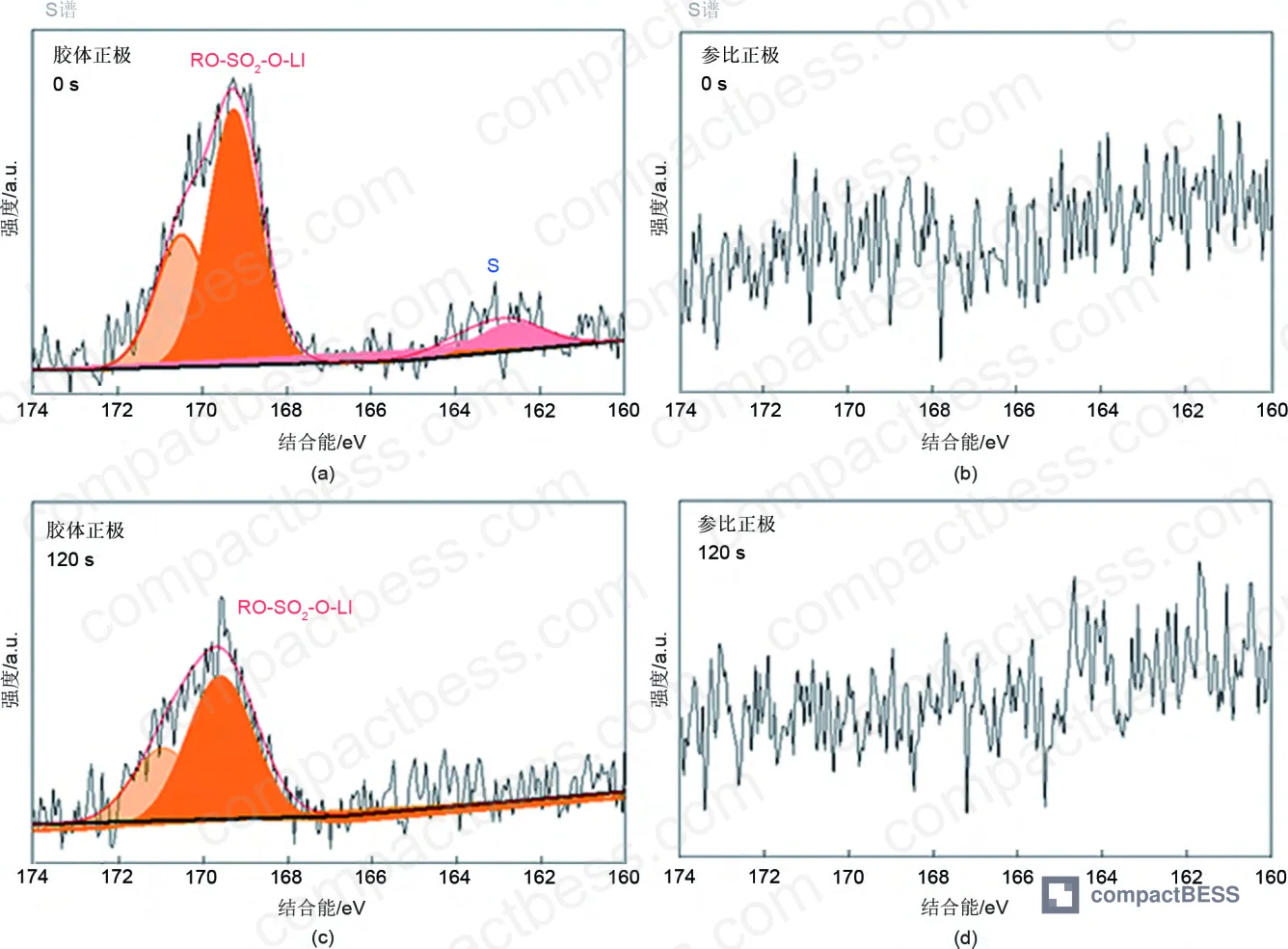
The XPS analysis confirms this interface chemistry. After 10 charge-discharge cycles, the gel-type cathode shows a clear S 2p signal at 163.0 eV (elemental S) and 169.2 eV (lithium alkyl sulfate, R–OSO₂OLi). After Ar⁺ sputtering for 120 seconds, the elemental S signal disappears but the alkyl sulfate signal persists — confirming that a stable, sulfate-rich interface layer has formed beneath the surface. The reference LFP cathode shows no S-containing signals under any condition.
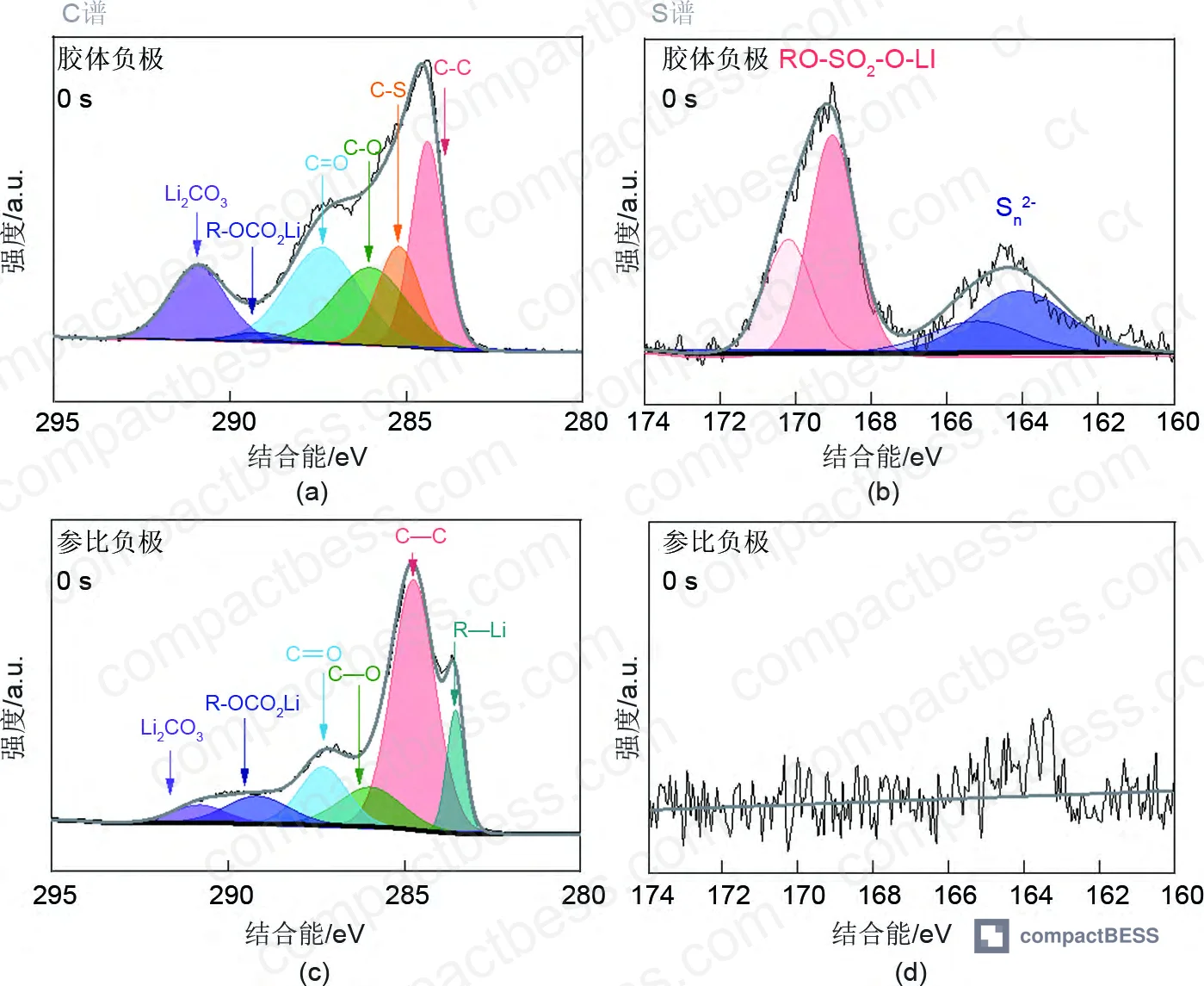
On the anode side, after 10 cycles the gel-type cell shows a C–S signal at 285.2 eV in the C 1s spectrum (corresponding to the sulfurized PEO-type gel component) and polysulfide signals (Sn²⁻) at 164.2 eV in the S 2p spectrum. This independently confirms that the gelation reaction has occurred at both electrodes — it’s not a surface coating applied externally, it’s a product of the cell’s own electrochemical cycling.
In supplier qualification, it’s worth noting that when examining early-cycle EIS data for cells claiming gel or semi-solid electrolyte design, three of the most common red flags are: no measurable decrease in Rct over the first 25 cycles (suggesting the gelation reaction hasn’t occurred or has been bypassed), anomalously high initial impedance (suggesting over-gelation during manufacturing), and inconsistent initial capacities across cells in the same batch (suggesting uneven additive distribution in the cathode coating).
Commercial Cell Validation: Model 71173, 320 Ah Format #
The transition from pouch-cell laboratory data to a commercial 320 Ah prismatic cell (model designation 71173) is the critical validation step that separates paper-level claims from procurement-relevant performance. The 71173 cell — named for its dimensional specifications — represents an industrial-scale implementation of the same Li₄SiO₄@S gel technology validated in the 2.5 Ah pouch format.
At this capacity class, the safety performance delta becomes the dominant procurement argument. Liquid LFP cells in large-format prismatic configurations carry thermal runaway risk that is not merely a function of chemistry but of the thermal mass, electrolyte volume, and pack geometry involved. The in-situ gelation mechanism reduces the quantity of free mobile organic solvent in the cell, which is the primary fuel source in a thermal runaway event — directly reducing the heat release after onset.
For grid-scale and C&I storage buyers evaluating LFP cells against safety certifications under IEC 62619 (industrial safety for secondary lithium cells) or UL 9540A (thermal runaway fire propagation in BESS), the gel-type architecture offers a structural advantage in both the nail penetration and thermal abuse test sequences. Buyers specifying to UN 38.3 transport requirements should also ask suppliers to confirm whether gel-type cells require re-classification relative to liquid-electrolyte cells of the same format — the answer depends on the degree of electrolyte immobilization achieved.
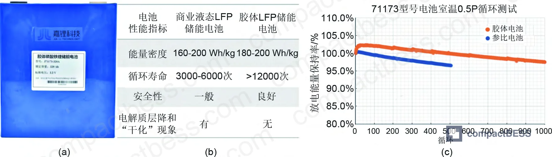
Honestly, the 320 Ah format in a prismatic case is where the market is right now for utility-scale storage. The question isn’t whether gel-type chemistry works at the pouch level — this data answers that. The question buyers should be asking is whether their supplier can maintain the additive loading uniformity (±0.1% by mass) across a 320 Ah electrode stack with its substantially larger coating area and tighter winding or stacking tolerances.
Practical Guidance for Buyers #
If you’re sourcing LFP cells for applications with ≥10-year design life, fixed installation, or elevated ambient temperature conditions (>35°C annual average), the electrolyte architecture of your cell deserves the same scrutiny as cycle count and C-rate specs. The standard datasheet doesn’t tell you whether the cell uses a liquid or gel electrolyte system, and most suppliers won’t volunteer the distinction unless you ask.
The capacity retention figures here — 94.4% at 1000 cycles, room temperature, 1C for the gel-type versus 84.8% for standard liquid LFP — translate directly into a warranty and total cost of ownership calculation. If your system integrator is sizing battery banks based on standard LFP retention curves and your cells are performing to gel-type curves, you’re carrying unnecessary capital cost in excess capacity. If it’s the reverse, you’re carrying warranty risk.
Key evaluation criteria before approving a cell supplier for stationary storage: request EIS data across the first 25 cycles (not just initial impedance), ask for high-temperature storage test results at ≥55°C, and verify that the supplier can provide batch-level coating uniformity data for the Li₄SiO₄@S additive. At CompactBESS, we work directly with verified Chinese manufacturers who have implemented this technology at commercial scale — connecting OEM buyers and storage integrators with qualified suppliers for technical specifications that don’t appear in standard commodity catalogs.
Need help identifying qualified suppliers for gel-type LFP energy storage cells? Talk to our sourcing team →
Supplier Qualification Questions #
- Can you provide EIS Nyquist plot data showing charge-transfer resistance (Rct) evolution from cycle 1 through cycle 25, and confirm that Rct at cycle 25 is ≤12 Ω for your standard gel-type LFP cell configuration?
- What is your measured capacity retention at 1000 cycles under 1C rate at 45°C, and can you share the full cycle-by-cycle decay curve to confirm the absence of nonlinear degradation onset before cycle 700?
- What is the Li₄SiO₄@S additive loading percentage (by mass) in your cathode formulation, and what is the batch-to-batch variation tolerance — specifically, can you confirm the target is 1.0% ±0.1% by cathode coating weight?
- Can you provide XPS S 2p spectral data from cathode samples cycled ≥10 times, confirming the presence of lithium alkyl sulfate (R–OSO₂OLi) at 169.2 eV as evidence of in-situ interface gelation?
- What is the measured capacity recovery rate after 7-day storage at 55°C, and is it confirmed at ≥100% (i.e., post-storage capacity equals or exceeds pre-storage baseline), tested per your internal protocol or against IEC 62619 conditioning requirements?
Sourcing Checklist #
- [ ] Supplier provides accelerated cycle test data at 45°C, 1C rate, to ≥1000 cycles with capacity retention ≥89.0% confirmed for gel-type LFP cells
- [ ] Cathode coating contains Li₄SiO₄@S at 1.0% ± 0.1% by mass, with batch release documentation showing additive uniformity across the electrode area
- [ ] Cell passes 55°C, 7-day high-temperature storage test with ≥100% capacity recovery measured by 0.1C discharge to 2.5V cutoff
- [ ] 4C high-rate discharge tested with ≥95% capacity retention relative to 0.2C reference, confirming gel-type architecture does not impair rate capability
- [ ] EIS data confirms Rct ≤12 Ω at cycle 25 (reference: gel-type cell should show progressive Rct reduction versus stable-or-increasing Rct in liquid-electrolyte baseline)
- [ ] Cell meets UN 38.3 transport certification and supplier clarifies whether gel-type electrolyte classification affects shipping documentation
- [ ] Safety performance validated under IEC 62619 or UL 9540A with thermal runaway heat release data available for the specific cell format (e.g., 71173 320 Ah or equivalent prismatic)
- [ ] Supplier can provide SEM/EDS elemental mapping data confirming uniform C and S coating layers on Li₄SiO₄ core in incoming QC inspection batches
Key Specifications Table #
| Parameter | Recommended Value | Verification Method |
|---|---|---|
| Cycle retention at 1000 cycles, 45°C, 1C | ≥89.0% | Pouch cell cycle test: 0.1C formation, then 1C CC-CV charge to 3.65V / 1C discharge to 2.5V at 45°C; record capacity each cycle |
| High-temperature storage capacity recovery | 100% | Charge to full SOC, store at 55°C for 7 days, discharge at 0.1C to 2.5V; compare to pre-storage 0.1C reference capacity |
| 4C discharge capacity retention | ≥96.2% | Discharge at 4C following standard 1C charge; compare to 0.2C reference discharge capacity |
| Charge-transfer resistance (Rct) at cycle 25 | ≤12 Ω | EIS Nyquist plot measurement at 50% SOC, 10 mHz–100 kHz sweep; fit mid-frequency semicircle |
| Li₄SiO₄@S cathode additive loading | 1.0% by cathode coating mass | ICP-OES or XRF on cathode material; cross-check via XPS S 2p signal presence at 163–169 eV post-cycling |
| Initial discharge specific capacity (1C, RT) | ≥130 mAh/g (per total cathode coating weight) | 0.1C formation cycles, then 1C discharge to 2.5V at 25°C ±2°C; normalize to total cathode coating mass |
Can’t find a supplier meeting these specs? Submit your requirements and we’ll match you within 48 hours.
Frequently Asked Questions #
Q: What is the difference between a gel-type LFP cell and a solid-state LFP cell?
Gel-type and solid-state are not the same architecture. In the gel-type system described here, the electrolyte gelation occurs in-situ during the first charge-discharge cycles — the cell is assembled with standard liquid electrolyte, and the Li₄SiO₄@S additive triggers a polymerization reaction that converts the electrolyte at the electrode interfaces into a PEO-type colloidal network. The bulk electrolyte retains some ionic mobility, which is why 4C rate capability is preserved. Solid-state cells use a fully solid separator and electrolyte layer, typically ceramic or polymer, with substantially different manufacturing requirements and currently much higher production cost. For stationary storage procurement, gel-type LFP is commercially available today; true solid-state LFP at large format is not.
Q: Why does the gel-type cell show a capacity increase during the first 50 cycles?
This is the sustained-release lithium mechanism working as designed. Li₄SiO₄@S releases active lithium ions gradually over the initial cycles, compensating for the irreversible lithium loss that occurs during SEI formation on the graphite anode. In coin-cell testing, the 2% loading version reached 152.5 mAh/g at cycle 10 before stabilizing — starting from an initial 146.2 mAh/g. If your incoming inspection protocol flags cells for capacity increase during formation cycling, you need to update the accept/reject criteria for gel-type LFP cells, or you will incorrectly reject good cells.
Q: Does the Li₄SiO₄@S additive affect the cell’s compatibility with standard BMS charge algorithms?
The charging voltage window (2.5–3.65V) and C-rate parameters are unchanged from standard LFP. The gelation reaction is electrochemically triggered and self-limiting — it doesn’t alter the cell’s equilibrium voltage curve or require modified charge termination logic. However, buyers integrating these cells into existing BMS platforms should confirm that the capacity climb during initial cycles doesn’t trigger a BMS over-capacity fault condition. For more on BMS compatibility with advanced LFP cell chemistries, review the relevant technical guidance.
Q: What format does the commercial version of this cell use, and what are its dimensions?
The commercial cell validated in this evaluation is the 71173 format — a prismatic cell with the designation derived from its physical dimensions — rated at 320 Ah. This capacity class targets grid-scale and large C&I storage applications. For buyers evaluating cell format selection and dimensional compatibility within a pack design, the 71173 footprint should be evaluated against your thermal management and busbar layout constraints before specifying.
Q: Is this technology covered under international safety certifications for stationary storage?
Gel-type LFP cells can be certified under IEC 62619 and UL 9540/9540A, but buyers must confirm that the specific cell model — not just the chemistry — has been tested. The in-situ gelation architecture reduces free liquid electrolyte volume and lowers exothermic heat release in thermal runaway scenarios, which provides inherent advantages in abuse testing. Suppliers should be able to produce DSC (differential scanning calorimetry) data showing reduced heat generation compared to liquid-electrolyte baseline cells of equivalent format.
Published by compactbess.com Technical Team | Request a sourcing quote
Data source: In-Situ Electrolyte Gelation and Lithium Compensation Strategies for Extended Cycle Life in LiFePO₄ Energy Storage Cells, H. Zhang et al., Journal of the Electrochemical Society, 2024
Content reviewed by dr.james.okafor | © compactbess.com — All rights reserved. Unauthorized reproduction prohibited.


