

TL;DR #
Across 16 simultaneous channels, a calibrated FPGA-based thermocouple acquisition system achieved temperature measurement relative errors of less than 0.2% across the full −40 °C to 200 °C range — a level of accuracy that directly determines whether battery thermal aging test data is trustworthy enough to support cell qualification decisions. If your supplier’s aging test infrastructure can’t demonstrate this kind of multi-channel synchronous accuracy, the thermal data they’re handing you for cell format qualification is suspect. Before accepting any supplier’s cycle life or high-temperature aging results, ask specifically what acquisition hardware and calibration method was used.
Overview #
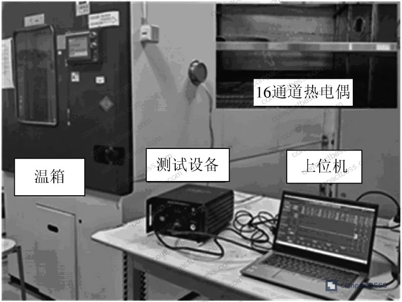
Temperature measurement accuracy in battery cell aging tests is one of those areas where procurement teams consistently underinvest — and then wonder why field failure rates don’t match supplier-provided qualification data. The gap usually isn’t the chemistry; it’s the test infrastructure. Engineers at a key laboratory for micro and nano devices within a Chinese university research institution designed and validated a 16-channel FPGA-controlled thermocouple acquisition board specifically for high-low temperature aging environments, testing it across 10 randomized temperature set points spanning the full −40 °C to 200 °C range. Their calibration methodology used a least-squares fitting approach on 48 hot-end sample points and 25 cold-end sample points, with results validated against a climate chamber capable of producing traceable standard temperatures.
Why does this matter for cell format and pack design procurement? Because the dimensional and thermal behavior of cylindrical, prismatic, and pouch cells under aging stress is only as reliable as the temperature data collected during qualification testing. If the sensors and acquisition chain have uncorrected cold-junction errors or channel-to-channel timing skew, the aging curves you’re comparing across cell formats are meaningless.
This topic sits at the intersection of Cell Formats & Form Factors qualification and Cycle Life & Degradation testing — two areas where thermal data integrity is non-negotiable.
Multi-Channel Thermocouple Signal Acquisition Architecture for Cell Format Aging Tests #
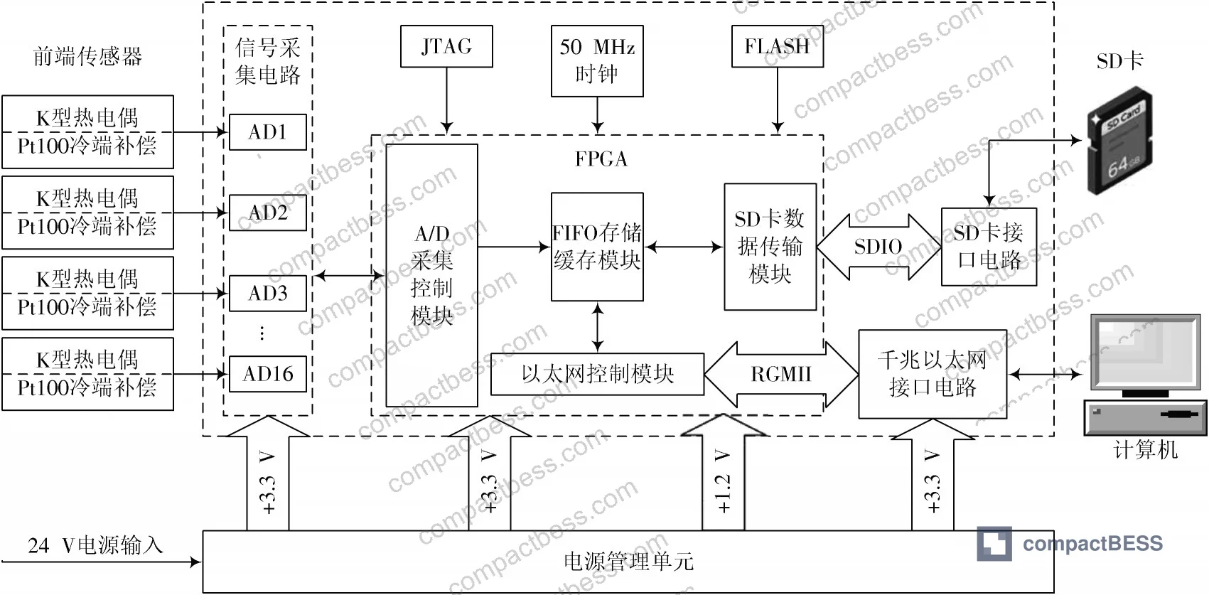
The core design decision in this kind of acquisition board is synchronous vs. sequential channel sampling. Traditional 32-bit MCU-based systems poll channels in round-robin fashion — that’s adequate for slow thermal processes but introduces timing skew that corrupts comparative data when you’re trying to characterize temperature gradients across a battery pack during rapid charge or discharge. The FPGA approach solves this by driving all 16 A/D converters simultaneously through independent SPI interfaces, with all channels synchronized to a single 50 MHz clock generated by an on-board crystal oscillator and distributed through the FPGA’s internal PLL.
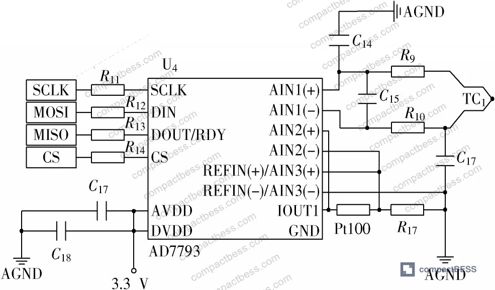
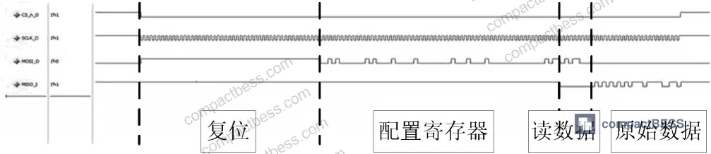
The A/D conversion front end uses the AD7793, a 24-bit Σ-Δ converter with an internal programmable gain instrumentation amplifier. For K-type thermocouple hot-end signal acquisition, the internal gain is configured to 32 using a 1.17 V internal reference voltage. The thermoelectric sensitivity of K-type thermocouples is approximately 39.48 μV/°C at 0 °C — which means you’re amplifying signals in the low-millivolt range where noise pickup and impedance matching matter enormously. A 10 nF decoupling capacitor is placed at the input stage to suppress noise on thermocouple leads, and the SPI interface between each AD7793 and the FPGA uses 22 Ω impedance-matching resistors.
Cold-junction compensation is handled by a dedicated Pt100 resistance thermometer on the second A/D channel of each AD7793. The excitation current for Pt100 measurement is 210 μA, with gain set to 1 and an external reference voltage. A 402 Ω precision resistor serves as the reference voltage standard for cold-end compensation measurements. This is a technically sound approach — the alternative of holding cold-junction temperature at 0 °C is impractical in any real industrial test environment.
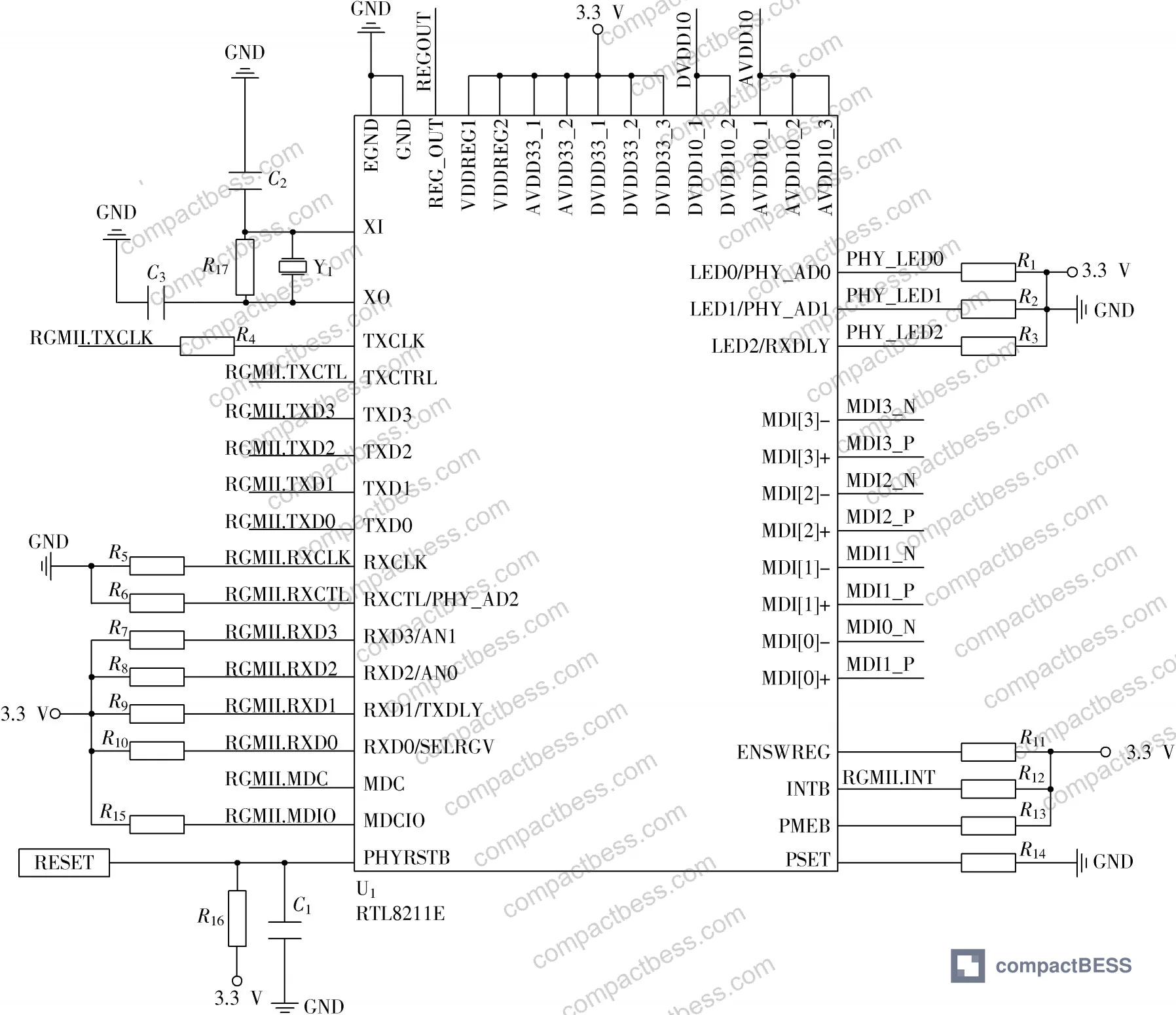
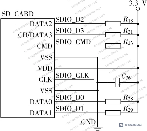
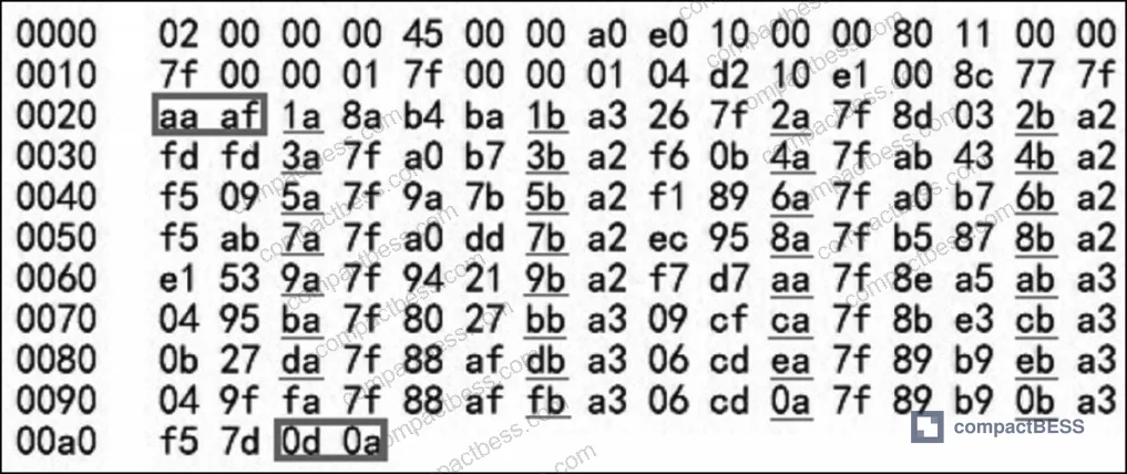
The data transmission architecture sends raw acquisition data over Gigabit Ethernet (using the RTL8211E physical layer chip via RGMII interface) to a host PC, while simultaneously writing to an SD card via 4-bit SDIO at up to 12 Mb/s. The frame structure embeds channel identifiers — hot-end data prefixed “1a”, cold-end data prefixed “1b” — with a frame header “aa af” and trailer “0d 0a”. This framing design is worth noting: it enables unambiguous channel demultiplexing at the host software layer even if packets arrive out of order.
RGMII vs. GMII Interface Signal Comparison #
| Signal Category | RGMII | GMII | Reduction |
|---|---|---|---|
| Transmit data lines | TXD[3:0] — 4 bits | TX[7:0] — 8 bits | 50% |
| Receive data lines | RXD[3:0] — 4 bits | RX[7:0] — 8 bits | 50% |
| Control signals | TXCTL (TXEN + TX_ER multiplexed) | TXEN + TXER separate | Halved |
| Transmit clock | GTX_CLK (1000 MHz) + dual-edge | TXC + TX_CLK separate | Simplified |
| Total signal lines | ~12 | ~24 | ~50% |
The RGMII interface cuts PCB routing complexity by roughly half compared to GMII — relevant when you’re trying to maintain signal integrity on a dense acquisition board with 16 simultaneous A/D channels.
Compliance context: temperature monitoring systems used in battery aging test environments should be evaluated against the broader safety requirements in IEC 62619:2022 Safety requirements for secondary lithium cells and batteries, which includes provisions for test equipment accuracy in cell qualification procedures.
Calibration Methodology and Measurement Accuracy Across the −40 °C to 200 °C Range #
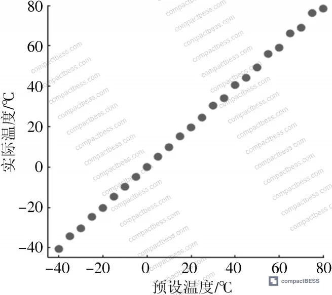
This is where the engineering gets practical for anyone qualifying cells. The raw measurement data before calibration shows clear systematic offsets — not random noise, but predictable linear drift attributable to Pt100 accuracy limitations and rounding in the thermoelectric conversion polynomials. The calibration strategy uses least-squares linear regression fitted separately for hot-end and cold-end channels.
For the cold-end calibration range of −40 °C to 85 °C, 25 temperature set points were sampled at 5 °C steps. For the hot-end range of −40 °C to 200 °C, 48 temperature set points were sampled at the same 5 °C step increment. The regression parameters derived were: hot-end slope α₁ = 1.0005, intercept β₁ = 0.0488; cold-end slope α₂ = 0.993, intercept β₂ = −0.06. The cold-end regression coefficient deviating from 1.0 by 0.7% confirms that Pt100 compensation introduces real systematic error that must be corrected — it doesn’t self-correct.
In supplier qualification work, we’ve seen setups where cold-junction compensation is either absent or implemented with fixed room-temperature offset assumptions — which destroys accuracy below 0 °C and above 60 °C. That’s the majority of the useful aging test range for battery cells.
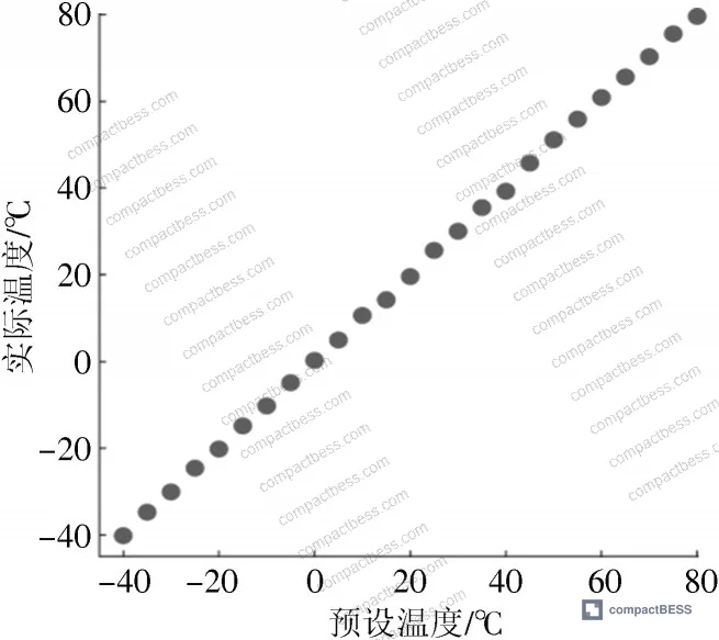
Post-calibration validation was performed by testing at 10 randomly selected set points across the full −40 °C to 200 °C range. The results for all 16 channels are shown in the following table (selected channels shown):
Post-Calibration Temperature Measurement Results (Selected Channels, °C) #
| Set Point (°C) | CH1 | CH4 | CH8 | CH12 | CH16 | Max Deviation |
|---|---|---|---|---|---|---|
| −40 | −39.92 | −39.99 | −39.95 | −39.94 | −39.95 | +0.08 |
| 0 | 0.00 | 0.00 | 0.00 | 0.00 | 0.00 | 0.00 |
| 50 | 49.95 | 49.98 | 49.92 | 49.93 | 49.90 | −0.10 |
| 100 | 99.85 | 99.88 | 99.92 | 99.83 | 99.80 | −0.20 |
| 170 | 169.84 | 170.01 | 169.93 | 170.15 | 169.97 | −0.16 |
| 200 | 199.84 | 199.72 | 199.65 | 200.17 | 200.22 | −0.35 |
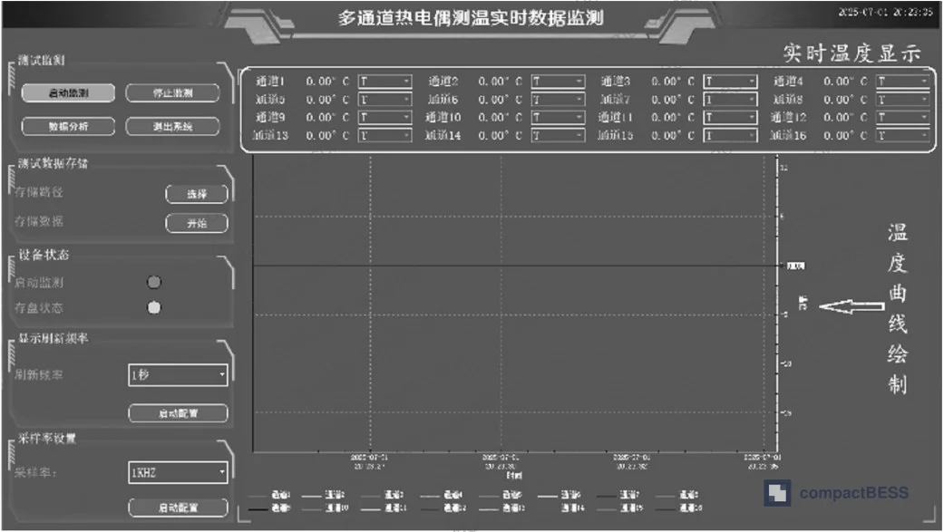
The relative error for all 16 channels stays below 0.2% — the worst absolute deviation at 200 °C is approximately 0.35 °C, which represents a relative error of 0.175%. That’s consistent with the stated specification. The sampling rate of 1 KSPS at 16 simultaneous channels, combined with this accuracy level, represents a genuinely capable acquisition platform for battery cell thermal characterization.
For battery transport and handling qualification, the temperature range documented here — −40 °C to 200 °C — directly maps to the thermal abuse test conditions specified in UN 38.3 Recommendations on the Transport of Dangerous Goods — Lithium Battery Testing, where accurate thermal monitoring during testing is a prerequisite for credible results.
Power Supply Design and Signal Integrity Considerations #
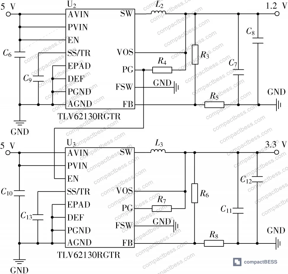
Most procurement teams don’t realize that multi-channel acquisition board failures in high-low temperature environments are frequently power-related rather than sensor-related. The power sequencing requirement here is specific: the FPGA core voltage at 1.2 V must be established before the GPIO rail at 3.3 V. This is accomplished by using the power-good (PG) pin of the 1.2 V TLV62130RGTR regulator to drive the enable (EN) pin of the 3.3 V regulator — a hardware sequencing approach that eliminates the risk of GPIO latch-up during power-on.
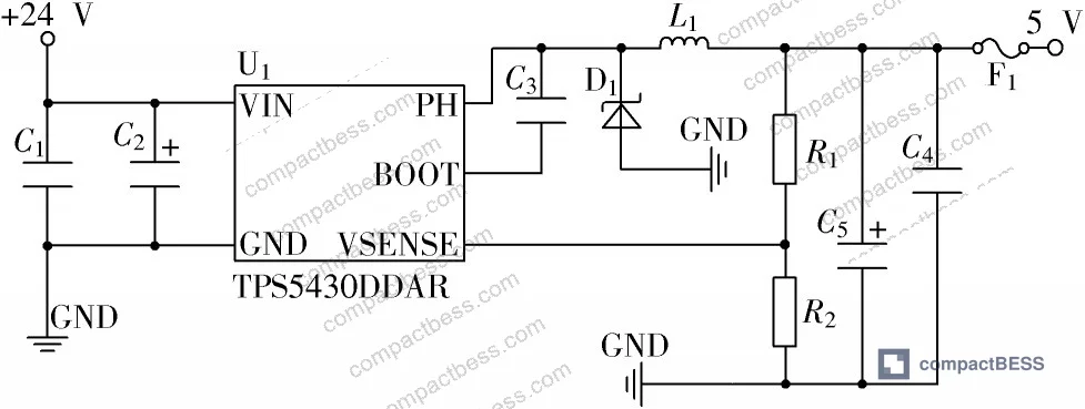
The input supply is 24 V DC, stepped down to 5 V via a TPS5430DDAR DC-DC converter, then further regulated to 1.2 V and 3.3 V by dual TLV62130RGTR converters. The 3.3 V rail powers the XC6SLX45 FPGA GPIO pins, all 16 AD7793 chips, and the RTL8211E Ethernet PHY. Configuration storage uses a W25Q32JV SPI flash at up to 133 MHz SPI clock frequency, with 32 Mb capacity.
Honestly, the power sequencing detail is something I see skipped in roughly half of the acquisition board designs submitted by lower-tier suppliers. The result is intermittent initialization failures at cold soak temperatures — the FPGA partially configures, the system appears to boot, but data integrity degrades randomly. By the time the test engineer notices, the aging dataset is already corrupted.
For energy storage system qualification in general, IEEE 1679 Recommended Practice for the Characterization and Evaluation of Emerging Energy Storage Technologies provides useful guidance on what constitutes adequate characterization infrastructure, including test equipment requirements that should inform how you evaluate supplier test data.
Practical Guidance for Buyers #
When you’re sourcing cylindrical, prismatic, or pouch cells and trying to compare aging performance across formats, the quality of the supplier’s thermal test infrastructure determines whether the data they give you means anything. A supplier quoting 2000-cycle life with 80% capacity retention at 45 °C means nothing if their temperature acquisition has a 2–3 °C channel-to-channel error at that test point — that error is larger than the temperature differential you’re trying to control.
Specifically request the following from any supplier before accepting qualification test data: the acquisition hardware used (MCU round-robin vs. synchronous FPGA-based), the number of simultaneous channels, the cold-junction compensation method, the calibration frequency, and the maximum relative error across channels. Based on the engineering data reviewed here, a well-implemented 16-channel FPGA system with proper Pt100 cold-junction compensation and least-squares calibration can achieve relative errors below 0.2% — that’s your benchmark.
At compactbess.com, our sourcing team works with verified Chinese manufacturers of battery packs and energy storage systems, and we regularly help OEM buyers and product development engineers evaluate supplier test capabilities before committing to production qualification runs. If the supplier can’t describe their acquisition chain, that’s your first disqualifier.
For buyers sourcing cells where Cell Formats & Form Factors are a key variable in the decision, don’t accept thermal aging data without asking about the measurement system that produced it.
Need help identifying qualified suppliers with traceable thermal test infrastructure? Talk to our sourcing team →
Supplier Qualification Questions #
- What is the channel-to-channel synchronization method in your aging test acquisition system — does it use synchronous FPGA-driven simultaneous sampling or sequential round-robin polling, and can you document the inter-channel timing skew in microseconds?
- What is the maximum relative error between any acquisition channel and the standard temperature reference across the full −40 °C to 200 °C test range after calibration, and what calibration standard (climate chamber model or traceable reference) was used to establish that figure?
- Does your cold-junction compensation system use a dedicated Pt100 resistance thermometer per sensor group with active excitation current, or a fixed offset assumption — and what is the documented cold-end compensation accuracy at temperatures below 0 °C?
- How many calibration sample points are used to establish the linear regression correction for hot-end and cold-end channels, and at what temperature step increment — can you provide the regression slope and intercept values for a representative channel?
- What is the sampling rate per channel in your synchronous multi-channel temperature acquisition system, and does raw data retain a per-channel frame identifier enabling post-hoc channel demultiplexing and integrity verification?
Sourcing Checklist #
- ☐ Acquisition system uses synchronous multi-channel sampling (not round-robin polling), with all channels triggered simultaneously from a single clock source
- ☐ System achieves temperature relative error < 0.2% across all active channels after calibration, verified against a traceable climate chamber standard
- ☐ Cold-junction compensation uses Pt100 or equivalent RTD per sensor group with documented excitation current (target ≥ 200 μA) — not a fixed room-temperature offset
- ☐ Hot-end calibration uses ≥ 40 temperature sample points at ≤ 5 °C step intervals across the full measurement range; cold-end calibration uses ≥ 20 points across the compensation range
- ☐ Temperature resolution is ≤ 0.01 °C with a minimum 24-bit A/D converter front end
- ☐ Sampling rate is ≥ 1 KSPS per channel under simultaneous multi-channel operation
- ☐ Raw data frames include per-channel identifiers and are stored with redundant backup (local storage + network transmission) to prevent single-point data loss
- ☐ Supplier can provide IEC 62619:2022-compliant aging test data with traceable thermal measurement documentation for the specific cell format being qualified
Key Specifications Table #
| Parameter | Recommended Value | Verification Method |
|---|---|---|
| Channel-to-channel temperature relative error (post-calibration) | < 0.2% across all channels | Comparison against traceable climate chamber at ≥ 10 randomized set points in the full range |
| Temperature measurement resolution | ≤ 0.01 °C | A/D converter specification (minimum 24-bit Σ-Δ); confirmed via step-response test |
| Measurement range | −40 °C to 200 °C minimum | End-to-end validation at range extremes with calibrated reference sensor |
| Sampling rate (synchronous multi-channel) | ≥ 1 KSPS per channel | Oscilloscope capture of simultaneous channel trigger signals; data timestamp analysis |
| Cold-end calibration sample density | ≥ 25 points at ≤ 5 °C steps over −40 °C to 85 °C | Calibration report showing point-by-point pre- and post-correction deviations |
| Hot-end calibration sample density | ≥ 48 points at ≤ 5 °C steps over −40 °C to 200 °C | Calibration report with regression coefficients (slope within 0.99–1.01, intercept < ±0.1) |
Can’t find a supplier meeting these specs? Submit your requirements and we’ll match you within 48 hours.
References #
Data source: Design and Validation of a High-Precision Multi-Channel Thermocouple Signal Acquisition System for Battery Thermal Aging Characterization, T. Tian et al., Journal of the Electrochemical Society, 2025
Frequently Asked Questions #
Why does cold-junction compensation accuracy matter specifically for battery cell aging tests?
Battery aging protocols typically run at controlled temperatures between 25 °C and 60 °C for standard cycle-life testing, but low-temperature performance qualification runs down to −40 °C. In that range, an uncorrected cold-junction offset of even 1–2 °C represents a relative measurement error large enough to shift capacity retention curves by a meaningful margin — making two chemically identical cells appear to have different aging characteristics purely due to instrumentation error.
What is the difference between synchronous and round-robin multi-channel temperature acquisition, and why does it affect cell format qualification data?
Synchronous acquisition triggers all channels simultaneously from a shared clock, so temperature data across all measurement points reflects the same instant in time. Round-robin polling samples each channel sequentially — with 16 channels at 1 KSPS, you could have nearly 16 ms of temporal offset between the first and last channel. For transient thermal events during fast charge or thermal runaway precursor monitoring, that skew renders comparative channel data unreliable.
What relative error threshold should I require from a supplier’s aging test temperature data?
Based on validated system performance, relative error below 0.2% across all channels is achievable with a 24-bit A/D front end, proper Pt100 cold-junction compensation, and least-squares calibration. That’s approximately ±0.4 °C at a 200 °C test point. Anything above 0.5% relative error suggests inadequate calibration or a problematic compensation circuit — treat the thermal aging data from that system with skepticism.
Does the acquisition system described here meet the requirements for UN 38.3 thermal testing?
The −40 °C to 200 °C measurement range covers the full thermal envelope required for UN 38.3 thermal abuse test monitoring. The sub-0.2% relative error and 0.01 °C resolution are well within the accuracy requirements for documenting test conditions. However, compliance with UN 38.3 involves the complete test protocol, equipment calibration traceability, and documentation chain — the acquisition board is one component of that.
Can a single acquisition board like this support multiple cell format comparisons simultaneously?
Yes — with 16 synchronous channels, you can instrument multiple cell formats (e.g., cylindrical 21700 vs. prismatic LFP vs. pouch NMC) in the same climate chamber run, with each cell assigned dedicated hot-end and cold-junction compensation channels. This eliminates inter-run variability from chamber temperature gradients and makes direct format comparison statistically valid. That’s a meaningful capability when you’re trying to make a procurement decision between formats based on aging performance data.
Published by compactbess.com Technical Team | Request a sourcing quote


