

TL;DR #
Field production data from a high-volume pouch cell module assembly line shows that insulation failures caused by metallic contamination particles as small as 120 µm in length can occur even with multiple cleanliness control measures in place — and that pre-weld insulation screening can reduce scrap costs from these failures by 90%. For buyers sourcing pouch cell modules or battery packs, this means your supplier’s End-of-Line (EOL) insulation test is too late in the process to protect you from costly rework and cascading material waste. Require evidence of a pre-weld insulation detection step as a mandatory process qualification criterion before approving any pouch module production line.
Overview #
Most procurement teams treat insulation resistance as a final-test metric — something you verify at EOL before the battery pack ships. That framing is exactly wrong for pouch cell modules, and it costs manufacturers and their customers real money. The engineering analysis here comes from process qualification work conducted at a volume powertrain manufacturing facility assembling pouch cell modules for new energy vehicles. The evaluation covered the full cell stacking and module assembly process chain, combining failure mode analysis, contamination forensics using electron microscopy, and live production trials of a dedicated pre-weld insulation detection system. Sample data was drawn from actual production line insulation failures, not laboratory simulations.
Pouch cells are structurally more vulnerable to insulation failure than prismatic or cylindrical formats. The laminate outer casing provides far less mechanical protection against particle intrusion than a steel or aluminum hard case. When you stack dozens to hundreds of pouch cells under module compression force, any metallic particle on a cell surface — whether deposited during tab cutting, component handling, or environmental fallout — can be driven through the insulation layer by that clamping pressure. The failure may not be detectable until the module is fully welded and powered up at EOL. By then, the fix requires destructive disassembly.
If you are evaluating cell formats and form factors for a new pack design, the insulation risk profile of pouch cells compared to hard-case formats is a procurement variable that rarely gets the attention it deserves. It should be part of your supplier qualification checklist from day one.


Pouch Cell Insulation Failure Modes During Module Assembly #
Understanding where in the process insulation fails is more useful than simply knowing that it fails. The production failure analysis identified three process stages as primary risk points, each with distinct contamination mechanisms.
Tab trimming contamination. When pouch cell tabs are trimmed to length, metallic slivers — sometimes as small as a few tens of microns — can remain on the cutting tool or become airborne and settle on adjacent cell surfaces. Once a contaminated cell is stacked into the module, compression force during assembly can drive those particles through the polymer insulation layer.
Surface contamination from handling and environment. Components arriving at the line, fixtures, conveyor surfaces, and general production environment all contribute metallic particle load. Electron microscopy on failed cells found iron particles measuring 120 µm in length and 28 µm in height embedded at insulation failure sites. Critically, in some failure cases no foreign particle was found at all — the failure was attributed to assembly-induced reduction of effective electrical clearance, meaning the compression geometry itself caused the insulation to degrade below the withstand voltage requirement.
Dimensional tolerance stack-up. This is the failure mode that surprises most buyers. Even with clean components, variation in cell thickness and interleave spacer dimensions means module clamping force is not uniformly distributed across all cells. Some cells receive higher-than-intended compression; their effective electrical clearance drops below the design minimum. The relevant standard governing clearance and creepage requirements is IEC 62619:2022 Safety requirements for secondary lithium cells and batteries, which mandates specific clearance values for high-voltage battery systems.
| Insulation Failure Root Cause | Process Stage | Detection Point (Standard Practice) | Detection Point (Pre-Weld System) |
|---|---|---|---|
| Metallic particle from tab cutting | Cell tab trimming | EOL (post-weld) | Pre-weld module level |
| Surface contamination from handling/environment | Cell stacking | EOL (post-weld) | Pre-weld module level |
| Compression-induced clearance reduction | Module clamping | EOL (post-weld) | Pre-weld module level |
| Reduced impulse voltage withstand (no particle found) | Assembly process | EOL (post-weld) | Pre-weld module level |
In a qualification run on a production line, three of six modules sampled from a single shift showed measurable insulation resistance degradation before welding — degradation that would have been caught only at EOL under the previous process flow, by which point all welded interconnects were non-reversibly bonded. This is exactly the kind of data that should change how you write your supplier process audit requirements.

Pre-Weld Insulation Detection: How the System Works #
The detection system is conceptually simple: simulate the welded electrical circuit before welding actually happens, then measure insulation resistance against the module housing. The engineering challenge is doing this reliably on a moving production line with cells whose tab positions vary due to bend angle and alignment tolerance.
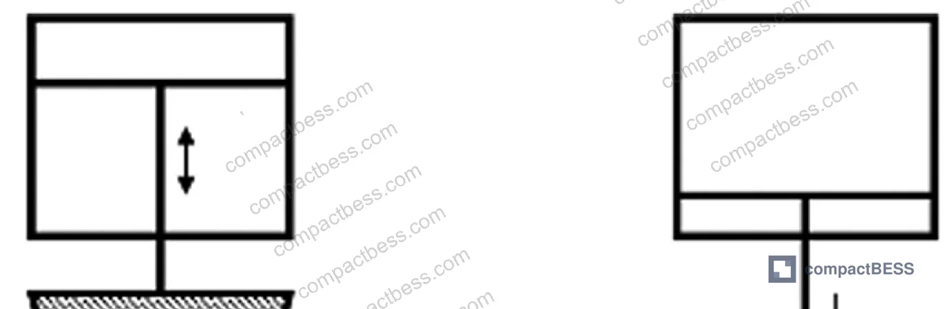
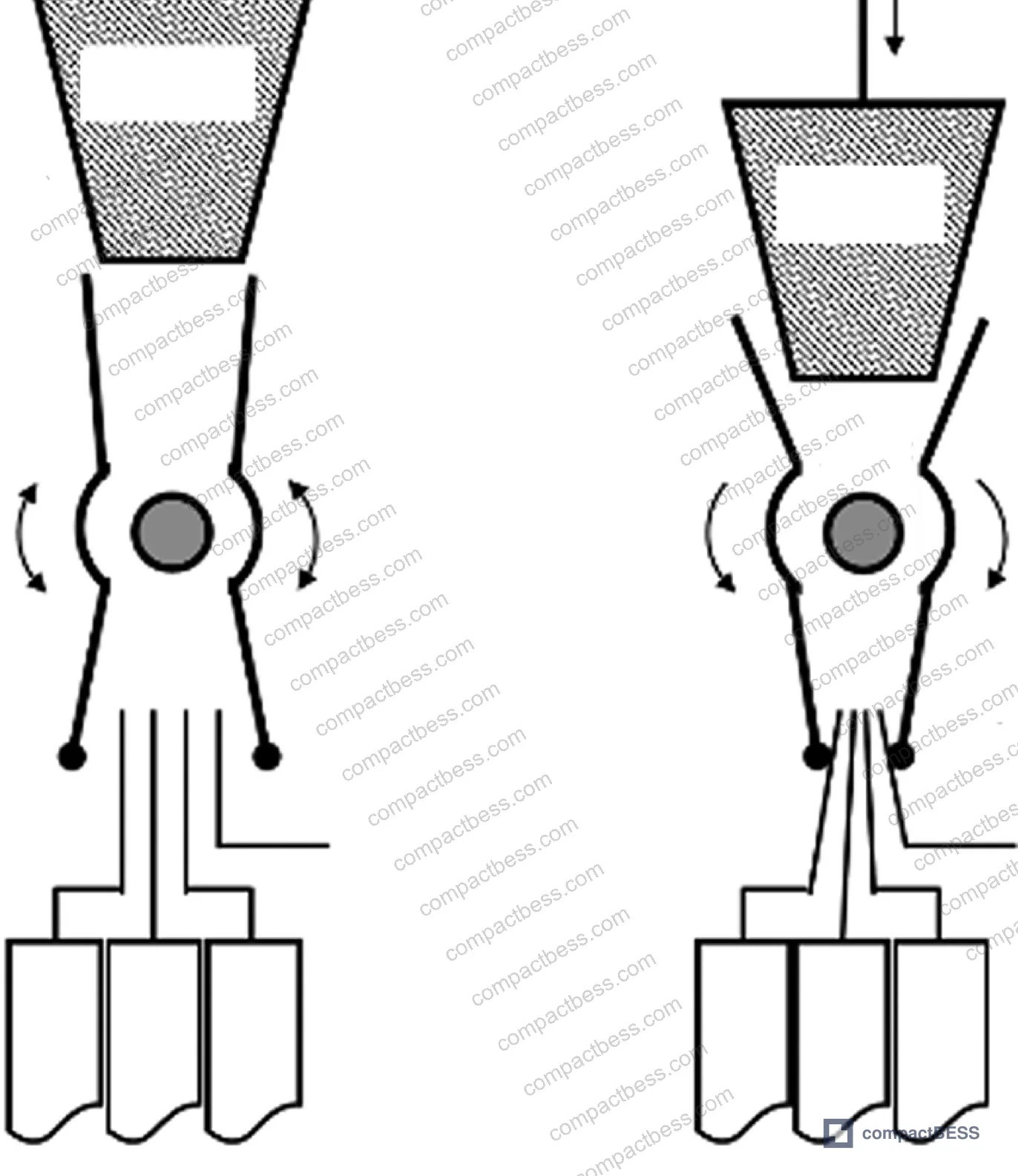
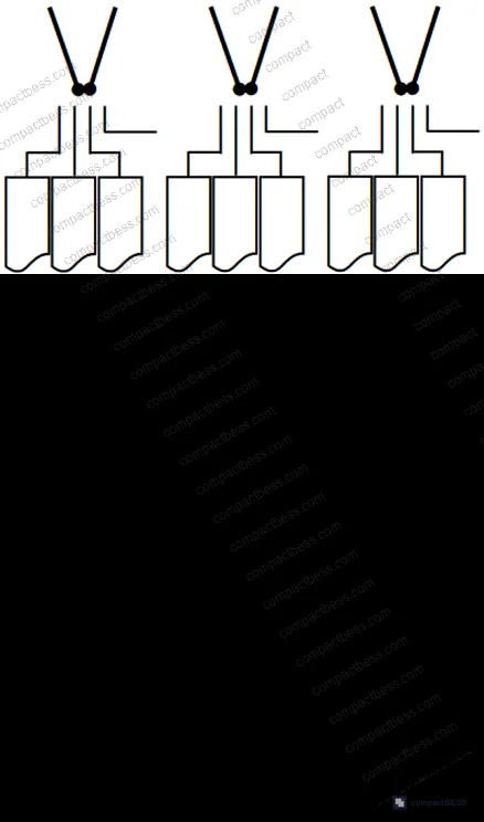
Mechanical clamping for circuit simulation. A wedge-block and torsion spring mechanism grips the cell tabs using beryllium copper contact tips. The beryllium copper was selected deliberately: it combines high conductivity (enabling resistance measurement across the clamped contact to verify clamp quality), good wear resistance (extending contact tip service life), and spring-like elasticity (ensuring consistent contact force despite tab position variation). The mechanism achieves self-centering through the wedge geometry, and a single pneumatic cylinder drives multiple clamp points simultaneously for synchronous operation across all cells in the module. Validated single-point clamping force: 58.8 N. Demonstrated service life: 30,000 clamping cycles.
The system detects four clamp quality states: normal grip, empty grip (no tab contact), partial grip (fewer tabs than expected), and loose grip (insufficient contact force). Any abnormal clamp state invalidates the insulation measurement for that module and flags it for re-check before proceeding.

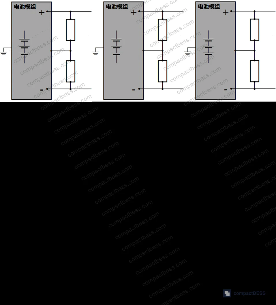
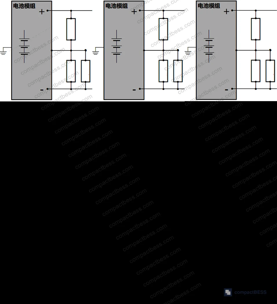
Insulation resistance measurement method. The measurement follows the approach specified in GB 18384-2020 for Class B voltage circuits. The module housing serves as the reference platform. Two voltmeters simultaneously measure the voltage between the positive terminal and housing (U1) and between the negative terminal and housing (U2). A precision reference resistor of 1 MΩ is then switched in parallel, measurements are repeated to obtain U1′ and U2′, and the insulation resistance values R1 (positive pole to housing) and R2 (negative pole to housing) are calculated by solving the resulting equation system. Voltmeter internal resistance is factored into the calculation.
The pass/fail threshold is derived from GB 18384-2020, which requires insulation resistance of not less than 100 Ω/V under maximum working voltage for DC circuits. Practically, the minimum acceptable insulation resistance is calculated using the full battery pack maximum working voltage — not just the module voltage — to ensure that module-level insulation is sufficient for pack-level voltage stress. If the pack design specification calls for a tighter value, that takes precedence.
This is important: most suppliers size their insulation test threshold to the module voltage. If your pack operates at 400 V or 800 V nominal, require the insulation threshold to be calculated at pack working voltage from the beginning. A module that passes at module-level voltage may still fail at pack level if insulation is marginally degraded.

System Verification Requirements and Production Results #
A detection system that has not been properly validated is just a piece of equipment on the line — it generates numbers but you cannot trust them. The verification protocol for this system covers three stages: functional check, repeatability check, and repeatability/reproducibility (R&R) study.
Functional check covers static verification (mechanical structure, electrical configuration, safety configuration, conformance to design standards) and dynamic verification (mechanical motion cycle, clamping and release, transport, position sensing, control logic, and cycle time within one standard work cycle).
Repeatability check assesses measurement system stability by running the same sample multiple times with the same operator and same system. The acceptance criterion is Cgk ≥ 1.33.
R&R study adds cross-operator and cross-sample variation to isolate measurement system contribution to total observed variance. The acceptance criterion is GR&R < 20% of product tolerance. This is the metric most suppliers skip, and it is also the one that exposes whether the measurement system is actually capable of detecting the insulation resistance differences you care about — especially near the pass/fail limit.
Honestly, the GR&R requirement is the one to push on in supplier audits. A supplier who can quote Cgk ≥ 1.33 but cannot show a complete R&R study with cross-operator data hasn’t fully validated their measurement system. It is a common gap.
After deployment on the production line, the pre-weld insulation detection system demonstrated a 90% reduction in scrap costs attributable to insulation failures. That figure reflects a combination of catching failures before welding (enabling cell-level replacement rather than full module or pack scrapping) and the earlier detection enabling rework to be contained at the lowest-cost assembly stage.
For context on how insulation performance interacts with long-term degradation, the SOH & RUL Prediction guidance covers how initial insulation quality at the module level correlates with in-service reliability over the battery’s service life.
Industry observation: most procurement teams don’t realize that insulation resistance requirements in national and international standards have been progressively tightened as pack voltages have increased from 400 V to 800 V platforms. The 100 Ω/V minimum in GB 18384-2020 was already a conservative floor for high-voltage systems. Some OEM-specific standards now impose 500 Ω/V or higher for 800 V platform packs. If your supplier is quoting compliance only to the statutory minimum, ask whether their insulation test threshold scales with your specific pack working voltage.
Relevant safety frameworks for buyers qualifying pouch module suppliers include UL 9540A Test Method for Evaluating Thermal Runaway Fire Propagation in Battery Energy Storage Systems — which explicitly addresses how electrical isolation failures can initiate thermal runaway propagation in multi-cell assemblies — and IEC 61960-3 Secondary lithium cells and batteries for portable applications for cell-level electrical safety parameters that feed into module insulation design.

Practical Guidance for Buyers #
If you are sourcing pouch cell modules or complete pouch-based battery packs, the single most impactful change you can make to your supplier qualification process is to require documented evidence of a pre-weld insulation detection step — not just an EOL insulation test result.
Ask for the insulation resistance threshold used in pre-weld testing, and verify that it is calculated against full pack working voltage, not module voltage. Require GR&R data for the measurement system (acceptance: < 20%), not just a functional system description. If the supplier cannot produce this data, their insulation test process has not been adequately validated, regardless of how many passed-lot certificates they can show you.
The failure mode to watch for during sample qualification: a batch of modules that all pass EOL insulation test but show higher-than-expected field failure rates in the first 6–12 months. This pattern often traces back to marginal insulation resistance at assembly — values that cleared the EOL threshold but degraded in service. The pre-weld detection approach catches this by screening before high-voltage circuit formation, when the failure is still reversible.
At CompactBESS, our sourcing team connects global OEM buyers with verified Chinese manufacturers who produce pouch cell packs, BMS modules, and complete battery systems — and we specifically evaluate supplier process documentation including insulation detection records as part of supplier qualification before recommending them for RFQ. If you’re designing around pouch cells and need suppliers with validated pre-weld process control, this is exactly the kind of technical detail we screen for.
Need help identifying qualified suppliers for pouch cell modules with verified pre-weld insulation testing? Talk to our sourcing team →
Supplier Qualification Questions #
- What is your pre-weld insulation resistance threshold, and is it calculated based on full battery pack maximum working voltage or module voltage only? Provide the numerical threshold in Ω and the pack working voltage it is derived from.
- What is the validated clamping force for your cell tab contact mechanism, and what is the rated service life in clamping cycles? We require ≥ 58.8 N single-point force and ≥ 30,000 cycle qualification.
- Can you provide GR&R study data for your pre-weld insulation measurement system showing total GR&R contribution of less than 20% of product tolerance, including cross-operator variation data?
- What Cgk value does your measurement system achieve in the repeatability study, and can you provide the raw data showing ≥ 1.33 Cgk across the qualification sample set?
- What is the smallest metallic particle size your cleanliness control process is validated to detect or exclude from cell surfaces prior to stacking? Reference your contamination monitoring data and the electron microscopy or particle count method used.
Sourcing Checklist #
- ☐ Supplier documents a dedicated pre-weld insulation detection step separate from EOL testing, with process records available for audit
- ☐ Insulation resistance acceptance threshold is ≥ 100 Ω/V calculated at full pack maximum working voltage per GB 18384-2020 (or higher per OEM-specific design requirement)
- ☐ Tab clamping mechanism service life is validated to ≥ 30,000 cycles with documented wear inspection intervals
- ☐ Measurement system GR&R study is available showing < 20% contribution to total measurement variance across multiple operators and sample units
- ☐ Measurement system repeatability study shows Cgk ≥ 1.33 on the insulation resistance characteristic
- ☐ Contamination control records include particle analysis data at cell stacking stage, with identification capability down to at least 120 µm particle size
- ☐ Supplier can demonstrate that pre-weld detection has achieved measurable reduction in insulation-related scrap costs (documented production data preferred)
- ☐ Insulation test method includes both positive-to-housing and negative-to-housing measurements (R1 and R2 independently), not a single composite reading
Key Specifications Table #
| Parameter | Recommended Value | Verification Method |
|---|---|---|
| Minimum insulation resistance (DC circuit) | ≥ 100 Ω/V × pack max working voltage (V) | Dual-voltmeter differential measurement per GB 18384-2020; 1 MΩ reference resistor method |
| Tab clamping force (single contact point) | 58.8 N | Load cell measurement at clamping mechanism; documented in equipment qualification report |
| Clamping mechanism service life | ≥ 30,000 cycles | Accelerated cycle test with wear inspection at 10,000-cycle intervals |
| Measurement system repeatability (Cgk) | ≥ 1.33 | Repeated measurement study — same sample, same operator, same system, minimum 25 measurement cycles |
| Measurement system R&R | < 20% of product tolerance | Full GR&R study — multiple operators, multiple sample units, crossing design |
| Reference resistor value for voltage-divider measurement | 1 MΩ (precision) | Calibrated resistance meter; tolerance ≤ 0.1% |
| Metallic particle contamination threshold (tab area) | < 120 µm characteristic length | Electron microscopy or calibrated optical particle counter at cell stacking station |
Can’t find a supplier meeting these specs? Submit your requirements and we’ll match you within 48 hours.
References #
Data source: Pre-Weld Insulation Testing Methods for Pouch Cell Battery Modules in High-Volume Automotive Assembly, B.-R. Shen et al., Journal of the Electrochemical Society, 2025
Frequently Asked Questions #
Why is pre-weld insulation testing more valuable than EOL testing for pouch cell modules?
Because welding is a non-reversible joining process. If insulation failure is only detected at EOL, rework requires destructive disassembly, and all welded interconnects and related components become scrap. Pre-weld detection catches the failure while the cell group is still mechanically reversible — replacing individual cells at module level rather than scrapping complete welded assemblies. Production data from this system shows a 90% reduction in insulation-related scrap costs after implementation.
What metallic particle size should buyers be concerned about in pouch cell assembly?
Electron microscopy on actual production failures identified iron particles as small as 120 µm in length and 28 µm in height as confirmed insulation failure causes. Importantly, some failures occurred with no recoverable particle — meaning compression-induced clearance reduction was the mechanism, not contamination. Both failure modes need to be controlled, not just cleanliness.
What is the correct insulation resistance minimum for a 400 V battery pack?
Per GB 18384-2020, the minimum is 100 Ω/V × maximum working voltage. For a 400 V pack, that gives a minimum of 40,000 Ω (40 kΩ). For an 800 V platform, the minimum rises to 80 kΩ. Some OEM specifications set tighter limits — 500 Ω/V is common for high-end automotive applications — which would give 400 kΩ minimum at 800 V. Always clarify which voltage your supplier is using as the calculation base.
Why is beryllium copper used for the contact tips in the clamping mechanism?
Three properties make it the right material for this application: high electrical conductivity (so contact resistance across the clamp can be measured to verify grip quality), good wear resistance (extending service life at the contact point), and spring-like elasticity (maintaining consistent contact force despite variation in tab bend angle and position). Alternatives like brass wear faster and have lower spring characteristics; pure copper is too soft. It is a deliberate engineering choice, not an arbitrary specification.
How does the clamping system detect abnormal grip states?
By measuring the electrical resistance between the two clamping tips on each contact point. Since beryllium copper is highly conductive, a normal grip through a properly contacted cell tab produces a predictable resistance range. An empty grip (no tab contact), partial grip (fewer tabs than specified), or loose grip (insufficient contact force) each produce resistance values outside this range. The system classifies four grip states and flags any abnormal condition before proceeding to insulation measurement, preventing false-pass results from a poorly seated clamp.
Published by compactbess.com Technical Team | Request a sourcing quote


