

TL;DR #
Wire-type thermocouples with near-zero-dimensional heat transfer geometry are fundamentally more compatible with closed-loop laser feedback calibration than ceramic-based thin-film thermocouples, which exhibit 2D heat dissipation that prevents clean step-temperature stabilization. For buyers sourcing battery thermal management sensors or BMS temperature measurement components, this distinction directly affects whether dynamic calibration data from a supplier is technically valid or merely approximate. Before accepting any thermocouple-based temperature specification from a cell or pack supplier, ask explicitly whether dynamic calibration was performed under closed-loop or open-loop conditions — the difference in time-constant accuracy is significant.
Overview #
Most procurement teams treat thermocouple specifications as a commodity item — they check the range, check the connector, and move on. That’s a mistake that shows up later in BMS validation failures and thermal runaway misdiagnosis. A multi-institutional research program involving a national key laboratory for extreme-environment optoelectronic measurement conducted systematic comparative dynamic calibration experiments on two fast-response thermocouple types — ceramic-substrate thin-film thermocouples and wire-shaped (fine-wire) thermocouples — using a high-power laser feedback control platform with real-time infrared thermometry. The experimental work covered both open-loop and closed-loop calibration conditions, with quantified time-constant extraction and temperature stabilization performance documented across multiple sensor samples.
This research is directly relevant to battery pack procurement because temperature sensing accuracy at the cell level is the foundation of reliable SOC estimation and SOH prediction. If the sensors embedded in a pack were calibrated under inadequate dynamic conditions — which open-loop laser calibration produces — then every temperature-dependent algorithm downstream carries systematic error.
Why Cell-Level Temperature Sensing Format Determines BMS Accuracy #
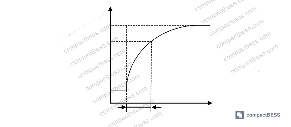
The core finding from this calibration research is that sensor geometry — specifically how a thermocouple’s hot junction transfers heat in two versus near-zero dimensions — determines whether a closed-loop laser calibration system can maintain a stable temperature plateau long enough to extract a valid time constant.
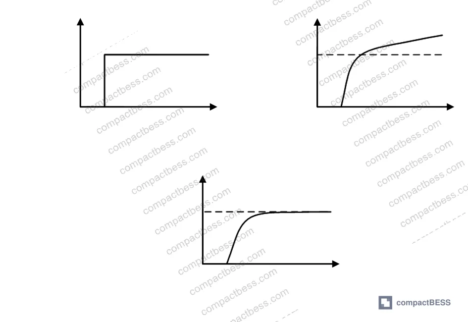
For thin-film thermocouples deposited on ceramic substrates (In₂O₃/ITO material system), the hot junction has a relatively large surface area. Heat flows longitudinally into the substrate and dissipates laterally by radiation and convection. This 2D heat transfer characteristic means that when laser power is applied, the junction temperature cannot be controlled precisely — it overshoots, undershoots, and oscillates. In open-loop testing at 250 W laser input, the equilibrium temperature reached 992.3°C, but equilibrium required more than 10 seconds, and the plateau was insufficiently stable to extract a time constant at all. Even with closed-loop feedback applied, the thin-film sensor’s time constant was only controllable to approximately 5 seconds — and temperature fluctuation at steady state remained visible.
Wire-shaped thermocouples (tungsten-rhenium alloy, 0.5 mm wire diameter in this evaluation) behave completely differently. The near-zero-dimensional point-like junction absorbs laser energy and equilibrates rapidly because there is minimal lateral thermal mass to manage. Under 30% laser power output (threshold voltage 1.2 V, corresponding to 731.5°C), the infrared pyrometer reached the threshold at 0.08 seconds. The junction temperature at that threshold detection moment was 650°C, and the system transitioned immediately to stable steady-state maintenance. The time constant extracted from the wire thermocouple response curve was approximately 1.8 seconds — a figure that is actually usable for dynamic performance characterization.
| Parameter | Thin-Film Thermocouple (In₂O₃/ITO) | Wire Thermocouple (W-Re, 0.5 mm) |
|---|---|---|
| Heat transfer geometry | 2D (lateral + longitudinal) | Near-zero-dimensional (point junction) |
| Open-loop equilibrium temperature | 992.3°C | Not reported (stable under closed loop) |
| Time to equilibrium (open loop) | >10 s | N/A |
| Time constant (closed loop) | ~5 s | ~1.8 s |
| Steady-state temperature stability | Poor (visible oscillation) | Good (rapid threshold lock) |
| Threshold detection time | Slow approach | 0.08 s to threshold voltage |
| Compatibility with laser feedback calibration | Limited | High |
The implication for battery pack sourcing is direct: if a supplier claims to use thin-film thermocouples for cell-surface temperature sensing and provides dynamic calibration data, ask specifically how that calibration was performed. If it was open-loop, the time-constant specification is essentially meaningless.
Closed-Loop Laser Feedback Calibration: System Architecture and Performance Data #
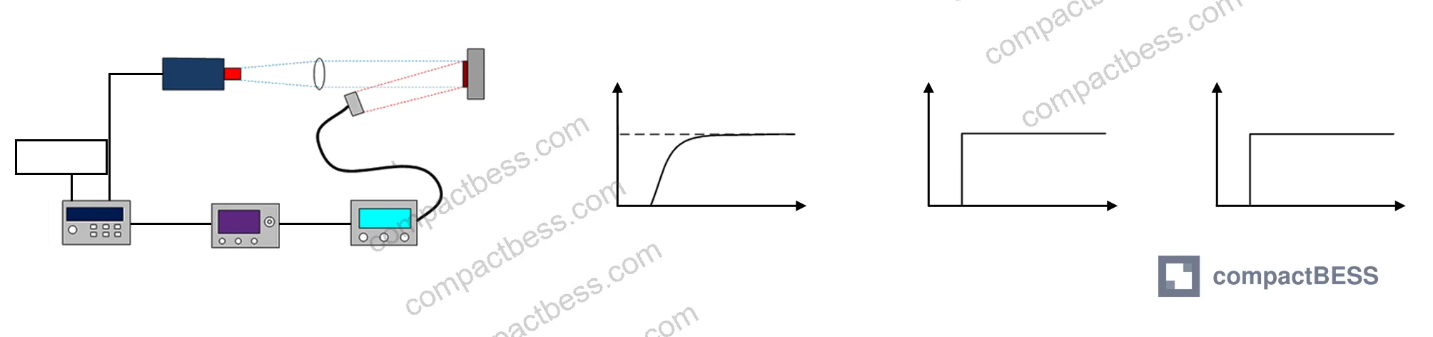
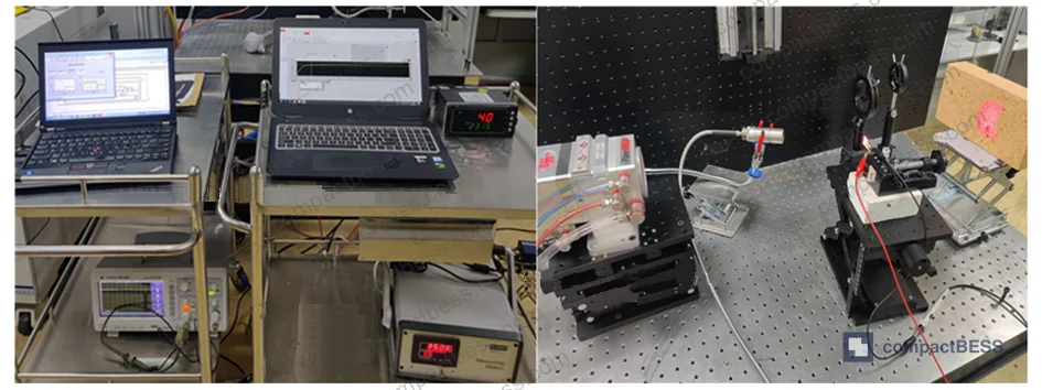
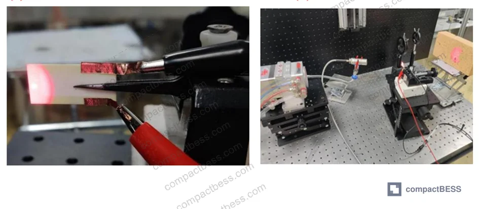
The calibration platform driving these results uses a 6 kW fiber-output semiconductor laser at 915 nm center wavelength as the thermal excitation source. The laser’s step signal rise time is less than 20 μs, and output power is linearly controllable via a 0–10 V DC voltage signal. These response characteristics are fast enough to act as a true step thermal input for the sensor under test.
The feedback measurement element is a high-speed infrared radiation thermometer with a response time of less than 10 μs, a measurement range of 350–3500°C, and a measurement accuracy of 0.45%. Its analog output is 0–10 V with good linearity across the temperature range. The controller uses a PXIe-5515 high-precision data acquisition card with 16-bit output data resolution, an update rate of 2.86 MSa/s, and output voltage range of ±10 V / ±5 V.
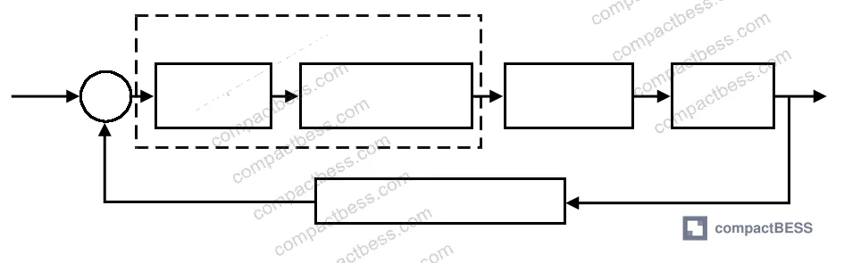
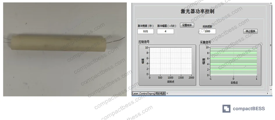
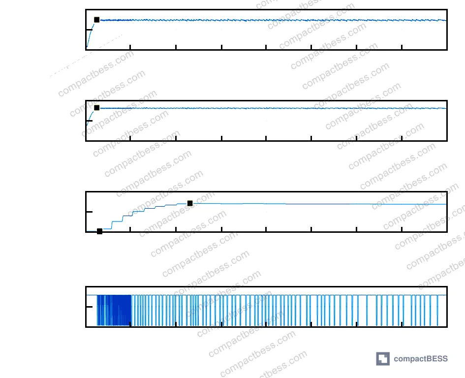
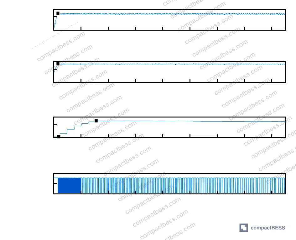
The control algorithm operates on a threshold comparison basis: every 10 sampled voltage points from the infrared thermometer are averaged, and that average is compared against the threshold voltage (1.2 V at the 731.5°C target, or 1.5 V at the higher 823.7°C target). If the average exceeds the threshold, the PXIe-5515 outputs 0 V — laser stops, junction cools. If below, it outputs 3 V with a 0.03 s pulse width (corresponding to 30% of maximum laser power), reheating the junction. This bang-bang threshold control produces stable temperature maintenance that would be impossible with constant-power open-loop excitation.
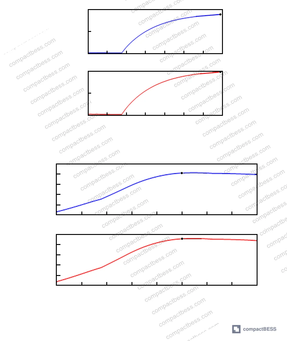
At 30% laser power with threshold 1.5 V (823.7°C target), the infrared thermometer output reached 1.208 V at t = 0.08 s, confirming that the feedback system locked onto the junction temperature within 80 ms. The wire thermocouple temperature curve then allowed clean extraction of the ~1.8 s time constant by the standard 63.2% rise-time method.
Most procurement teams don’t realize that the boundary condition imposed by a laser thermal excitation source is fundamentally different from the constant-temperature environments used in traditional furnace or bath calibration. Laser heating imposes a Neumann (constant heat flux) boundary condition, not the Dirichlet (constant temperature) condition of a furnace or the convective condition of a temperature bath. Without feedback control, you cannot extract a valid time constant from laser-heated calibration data — you’re measuring a combined artifact of the sensor and the boundary condition, not the sensor alone.
Failure Data: What Happens Without Feedback Control #
In open-loop dynamic calibration testing of the In₂O₃/ITO ceramic thin-film thermocouple at 250 W constant laser power, equilibrium temperature reached 992.3°C but the time to reach any semblance of a stable plateau exceeded 10 seconds in all tested samples. Time-constant extraction was impossible — not just difficult, impossible. The “equilibrium” state was not a true plateau but a slowly drifting temperature that never fully stabilized within the observation window. This is a direct consequence of the 2D heat dissipation geometry overwhelming the laser’s ability to establish a controlled thermal step.
This isn’t an edge case. It’s a structural limitation of applying constant-power laser heating to any sensor with significant lateral thermal mass. The failure mode is invisible in a supplier’s specification sheet — they will report a time constant number, but that number was either derived under conditions that don’t produce a valid step response, or estimated analytically rather than measured.
Honestly, most buyers over-specify thermocouple range and under-specify calibration methodology. A supplier quoting a ±1°C accuracy specification without being able to describe the dynamic calibration conditions that generated that number is quoting a static accuracy that tells you nothing about performance during transient thermal events — which is precisely when accurate sensing matters most in a battery system.
Practical Guidance for Buyers #
When you’re evaluating cell packs or BMS assemblies that include embedded temperature sensing, the sensor format and its calibration validity are procurement variables, not just engineering curiosities. Wire-type thermocouples with 0.5 mm or smaller junction diameters are measurably better candidates for dynamic calibration because their point-like heat transfer geometry allows closed-loop systems to establish and maintain a thermal plateau. Time constants in the 1.8 s range are achievable with proper calibration; thin-film sensors under identical calibration methodology produced time constants of approximately 5 s with visible steady-state instability.
For compliance purposes, temperature measurement systems in battery packs should align with the dynamic performance requirements embedded in safety standards. IEC 62619:2022 Safety requirements for secondary lithium cells and batteries specifies thermal protection thresholds that depend on accurate temperature measurement. If the sensor’s time constant is too slow — or the time constant specification is based on invalid open-loop calibration — the pack may not respond within the protection window defined by the standard.
The IEC 61960-3 standard for secondary lithium cells and batteries for portable applications references temperature measurement under discharge and charge test conditions, which requires that sensors track cell surface temperature with sufficient dynamic fidelity. A sensor with a 5 s time constant in a pack experiencing a 2–3 s thermal transient will systematically underreport peak temperature.
At compactbess.com, we work directly with verified Chinese manufacturers of battery packs and BMS modules, and our sourcing team can help you identify suppliers who can document the calibration methodology behind their temperature sensor specifications — not just the sensor type and range. For applications where thermal protection response time is a safety-critical parameter, that documentation matters.
Need help identifying qualified suppliers for battery packs with validated temperature sensing? Talk to our sourcing team →
Supplier Qualification Questions #
- What is the wire diameter of the thermocouple junctions used in your BMS temperature sensing elements, and can you confirm it is ≤0.5 mm to support near-zero-dimensional heat transfer for valid dynamic calibration?
- Was the time-constant specification for your embedded thermocouples derived from closed-loop or open-loop calibration? If open-loop, how was temperature plateau stability confirmed given that open-loop laser excitation at constant power produced equilibrium times exceeding 10 s in comparative testing?
- Can you provide the calibration excitation source type (furnace, bath, laser, other), the boundary condition category (constant temperature, constant heat flux, convective), and the measured plateau stability at the target calibration temperature?
- For thin-film thermocouple sensors, what is the substrate material and hot-junction surface area, and how does your calibration method account for the 2D lateral heat dissipation that causes steady-state temperature oscillation under laser excitation?
- What is the response time of the temperature measurement feedback element used in your calibration system, and is it below 10 μs (or equivalent) to ensure the feedback signal does not introduce lag that degrades the extracted time constant?
Sourcing Checklist #
- ☐ Wire thermocouple junction diameter is ≤0.5 mm, consistent with near-zero-dimensional heat transfer geometry that enables valid closed-loop dynamic calibration
- ☐ Supplier can provide dynamic calibration records showing closed-loop (not open-loop) excitation, with documented plateau stability and time-constant extraction via the 63.2% rise-time method
- ☐ Infrared or non-contact thermometer used in calibration feedback has a response time ≤10 μs and measurement accuracy ≤0.45% across the target temperature range
- ☐ Thin-film thermocouple samples, if used, show time constant ≤5 s under closed-loop calibration conditions, with visible plateau stability (not a drifting equilibrium exceeding 10 s)
- ☐ Temperature sensing specification complies with thermal protection thresholds under IEC 62619:2022, with sensor time constant documented relative to the protection response window
- ☐ Calibration system excitation source (laser or equivalent) has step signal rise time ≤20 μs to qualify as a valid step thermal input
- ☐ Supplier can distinguish between Dirichlet (constant temperature) and Neumann (constant heat flux) boundary conditions in their calibration setup and confirm which condition their reported accuracy is based on
- ☐ For UN 38.3 transport certification documentation, supplier can confirm that temperature sensor dynamic response was validated under conditions representative of actual transient thermal events, not just static accuracy
Key Specifications Table #
| Parameter | Recommended Value | Verification Method |
|---|---|---|
| Wire thermocouple junction diameter | ≤0.5 mm | Physical measurement / supplier datasheet |
| Dynamic calibration time constant (wire thermocouple) | ≤1.8 s | Closed-loop laser feedback calibration, 63.2% rise-time method |
| Dynamic calibration time constant (thin-film thermocouple) | ≤5 s | Closed-loop feedback calibration with confirmed plateau stability |
| Calibration feedback thermometer response time | ≤10 μs | Instrument specification sheet |
| Calibration feedback thermometer accuracy | ≤0.45% | Calibration certificate |
| Laser excitation step rise time | ≤20 μs | Laser system specification |
| Infrared thermometer measurement range | 350–3500°C (or application-appropriate subset) | Instrument datasheet |
| Controller output resolution | ≥16-bit analog output | DAQ card specification |
Can’t find a supplier meeting these specs? Submit your requirements and we’ll match you within 48 hours.
References #
Data source: Laser Feedback Control for Step Dynamic Calibration of Fast-Response Thermocouples in Extreme Temperature Environments, Q.-P. Cheng et al., Measurement Science and Technology, 2023
Frequently Asked Questions #
What is a thermocouple time constant and why does it matter for battery packs?
The time constant is the time required for a thermocouple to reach 63.2% of a step temperature change. For battery packs, this determines how quickly the BMS thermal protection circuit receives an accurate temperature signal during a rapid thermal event — a slow time constant means delayed protection response.
Why can’t open-loop laser calibration produce a valid time constant?
Open-loop constant-power laser excitation imposes a constant heat flux boundary condition (Neumann), not a constant temperature condition. This means the sensor temperature never stabilizes at a true plateau — it slowly climbs — making it impossible to measure the sensor’s intrinsic response time as distinct from the ongoing thermal input. In testing, open-loop equilibration of thin-film thermocouples exceeded 10 s with no stable plateau, rendering time-constant extraction impossible.
Is a 1.8 s time constant actually fast enough for lithium-ion cell protection?
It depends on the thermal event profile. For gradual overcharge or over-discharge events, 1.8 s is adequate. For fast-onset thermal runaway propagation — which can escalate in under 1 s — even wire thermocouples with 1.8 s time constants may lag. This is why placement location, sensor-to-cell contact quality, and BMS algorithm design matter alongside the sensor specification itself.
What is the difference between thin-film and wire thermocouples for battery applications?
Thin-film thermocouples are deposited as a 2D layer on a substrate and have larger hot-junction surface areas with significant lateral heat dissipation, making them harder to dynamically calibrate but easier to integrate into flat surfaces. Wire thermocouples have point-like junctions with near-zero-dimensional heat transfer, making them much more responsive and more accurately calibratable. For high-speed thermal event detection in battery packs, wire thermocouples with small wire diameters are the better-performing format. For cell format and geometry guidance see Cell Formats & Form Factors.
Does IEC 62619 specify thermocouple type or calibration method for battery temperature sensors?
IEC 62619:2022 specifies thermal protection requirements and temperature thresholds but does not mandate a specific sensor type or calibration methodology. It is the buyer’s responsibility to ensure that the sensing system embedded in the pack has sufficient dynamic fidelity to detect conditions within the protection window — which requires evaluating the sensor’s time constant against the expected thermal event speed. Also see UN 38.3 transport certification requirements for temperature-related test conditions during transport qualification.
Published by compactbess.com Technical Team | Request a sourcing quote


