

TL;DR #
Across six serpentine liquid cooling plate designs tested on a 43 kWh LFP battery pack (48 cells, two modules), all configurations held maximum pack temperature below 39 °C and inter-cell temperature differential at approximately 2.1 °C — but flow resistance dropped significantly as channel count increased, from over 1,400 Pa at 3 channels down to around 1,000 Pa at 8 channels. For buyers specifying thermal management in stationary BESS enclosures, this means channel count selection is primarily a hydraulic pump-load and manufacturing-cost decision, not a cooling-performance decision. Specify a 5-channel serpentine plate with optimized manifold geometry and demand Fluent-verified flow resistance data below 650 Pa before approving a supplier’s design.
Overview #
Most procurement teams evaluating liquid-cooled battery pack designs fixate on maximum temperature as the headline spec and stop there. That’s a mistake — because the data consistently shows that beyond a threshold of moderate channel count, maximum temperature variations between designs compress to within 0.2 °C of each other, while flow resistance differences remain substantial and directly drive pump energy consumption over the product’s service life. The engineering question shifts from “does it cool adequately?” to “what does it cost to run it?”
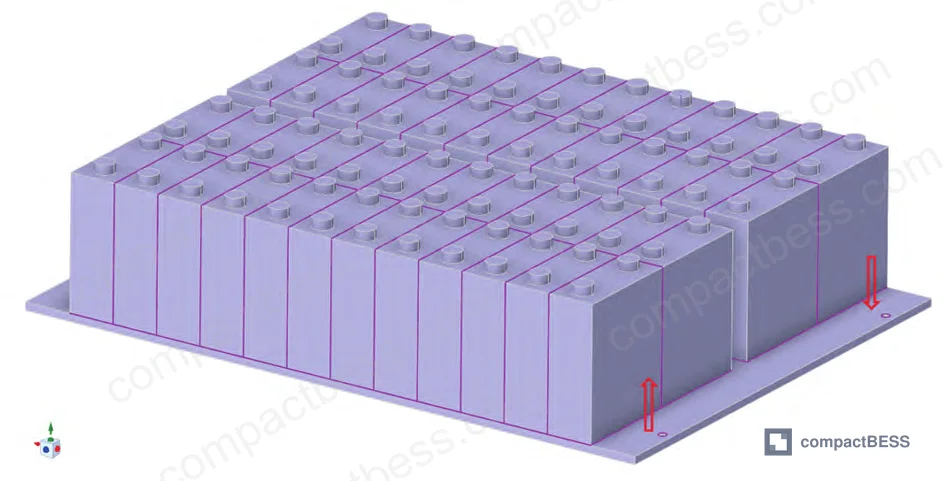
The analysis supporting this article draws from CFD simulation work conducted across a university-industry collaboration examining a real production-scale 43 kWh energy storage battery pack. The study used a validated finite-volume model (mesh count: 17,970,457 elements, confirmed grid-independent) with COUPLED algorithm pressure-velocity coupling and second-order upwind spatial discretization — rigorous enough to treat the flow resistance outputs as engineering-grade data, not rough estimates. Six distinct cooling plate designs were evaluated under identical boundary conditions, with inlet coolant flow of 0.05 kg/s and simulated 1C discharge heat generation of 17 W per cell.
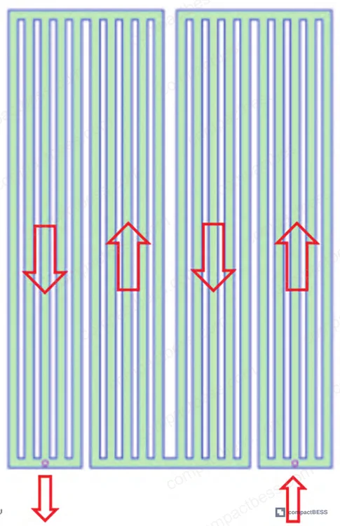
The pack configuration used 280 Ah prismatic LFP cells with dimensions of 72 mm × 208 mm × 173 mm, internal resistance of 0.22 mΩ, density of 2,219 kg/m³, and specific heat capacity of 1,000 J/(kg·K). Thermal conductivity was strongly anisotropic: 2.5 W/(m·K) in the x-direction (cross-lamination) versus 12 W/(m·K) in the y and z directions. These figures matter when you’re evaluating whether a supplier’s cooling plate placement and thermal interface material selection are actually aligned with the cell’s heat dissipation geometry.
Liquid Cooling Plate Channel Count: Thermal Performance vs. Flow Resistance #
The core finding here is counterintuitive to engineers who haven’t run this comparison before. More channels does not meaningfully improve cooling — but it does reduce parasitic pump load.
Across all six designs — 3, 4, 5, 6, 7, and 8 parallel serpentine channels — maximum pack temperature stayed below 39 °C and average temperature held at approximately 34.3 °C. The spread between best and worst thermal performer was less than 0.2 °C. From a cooling standpoint, they’re functionally identical.
Flow resistance is where the designs diverge sharply.
| Cooling Plate Configuration | Max Pack Temperature (°C) | Avg Pack Temperature (°C) | Flow Resistance (Pa) |
|---|---|---|---|
| 3-channel serpentine | ~38.55 | ~34.35 | ~1,400 |
| 5-channel serpentine (baseline) | ~38.45 | ~34.25 | ~1,101 |
| 5-channel serpentine (optimized) | ~38.35 | ~34.15 | 640.6 |
| 8-channel serpentine | ~38.35 | ~34.05 | ~1,000 |
The mechanism is straightforward: as channel count increases at fixed total inlet flow (0.05 kg/s), coolant velocity in each individual channel drops, reducing both the along-path friction loss (proportional to v²) and the local turbulence losses at manifold junctions. Reynolds number at the inlet was calculated at 5,273.5 — solidly turbulent — but that Re drops in each sub-channel as flow splits.
Honestly, most procurement teams over-specify channel count chasing marginal thermal gains that the data shows don’t exist. The real variable you should be auditing is manifold geometry — specifically the confluence zone dimensions at each channel turn, because that’s where localized vortex formation drives disproportionate pressure drop.
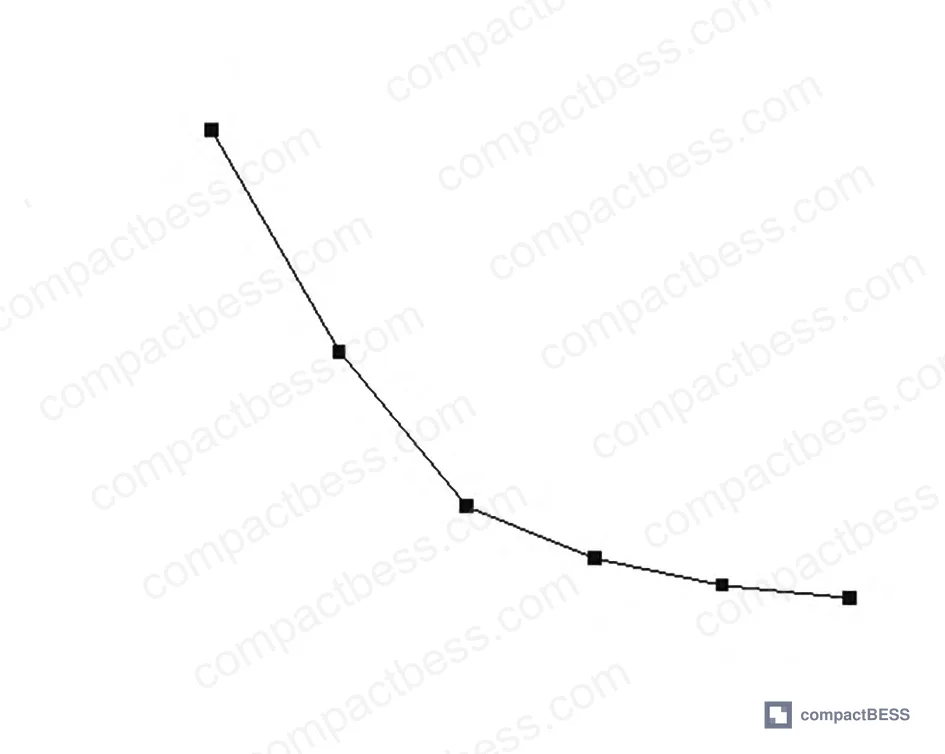
The 3-channel and 4-channel designs did show slightly weaker thermal performance than the others — attributable to lower effective contact area between coolant channels and cell faces. But “slightly weaker” here means the max temperature difference versus the 8-channel design is still under 0.2 °C. Unless your system is operating in an already-hot ambient with minimal margin to the 40 °C upper operating limit, this doesn’t matter.
Serpentine Manifold Optimization: Reducing Flow Resistance Without Sacrificing Cooling Performance #
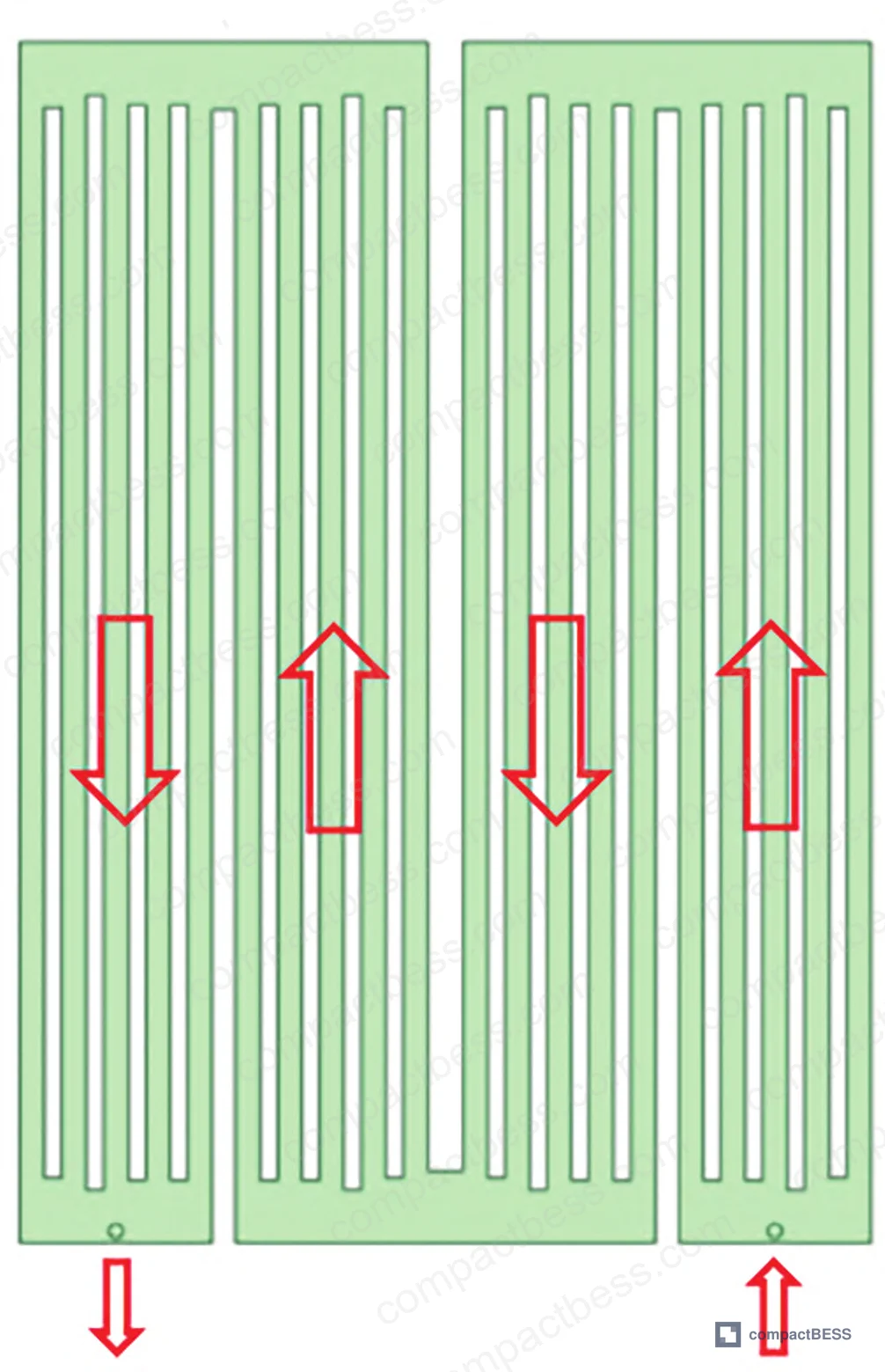
The 5-channel design was selected as the optimization candidate — not because it’s the thermal best-performer, but because it balances flow resistance, manufacturing complexity (cooling inlet/outlet on the same side, 12 mm port diameter, 20 mm channel width, 6 mm plate thickness), and tooling cost.
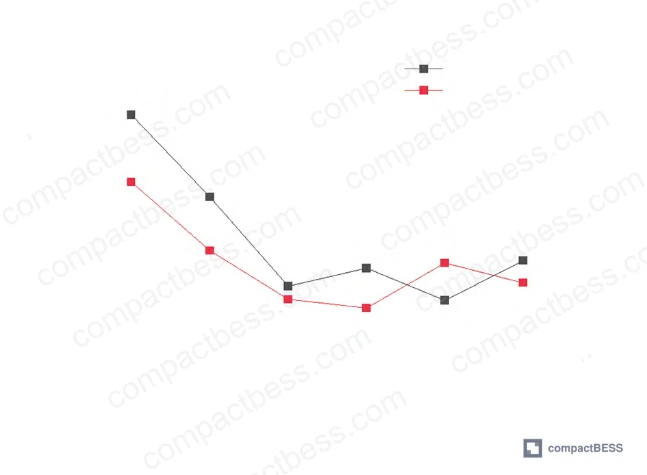
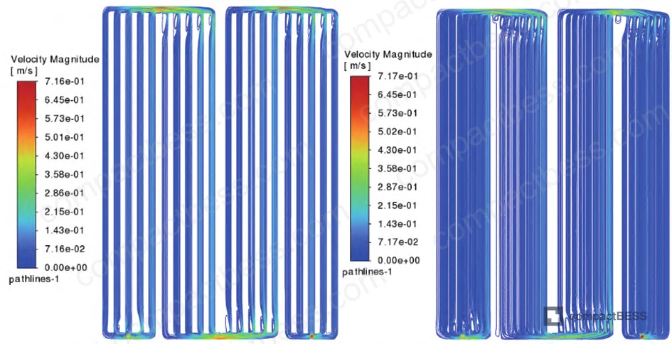
The optimization targeted the confluence zone dimensions at each channel turn — the dead-flow regions where velocity spikes and vortex formation concentrate pressure loss. Six geometric design variables (X1–X6), representing four inter-channel gap dimensions and two serpentine loop gap dimensions, were varied across a range of 20–60 mm. Latin Hypercube sampling generated 43 sample points, and a Response Surface Method surrogate model was constructed with R² = 0.987 for flow resistance prediction and R² = 0.911 for outlet temperature — both above the 0.9 threshold for engineering-grade predictive accuracy.
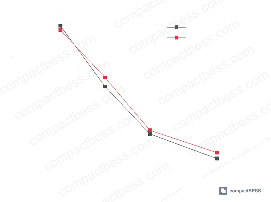
NSGA-II multi-objective optimization converged on a solution with outer gap dimensions slightly larger than inner channel gaps — producing what the velocity plots describe as a “crescent” profile that suppresses vortex formation at manifold turns.
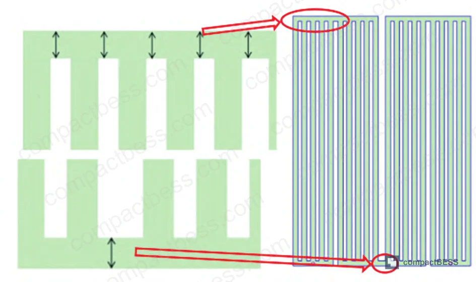
Optimized design variables: X1 = 54 mm, X2 = 44 mm, X3 = 52 mm, X4 = 52 mm, X5 = 56 mm, X6 = 60 mm.
NSGA-II predicted flow resistance: 590.9 Pa. Fluent CFD validation returned 640.6 Pa — a 7.8% error, which is acceptable for surrogate model predictions in this geometry class. That’s a reduction from the baseline 5-channel plate’s 1,101 Pa down to 640.6 Pa — a 41.8% reduction in flow resistance with no meaningful change in thermal performance.
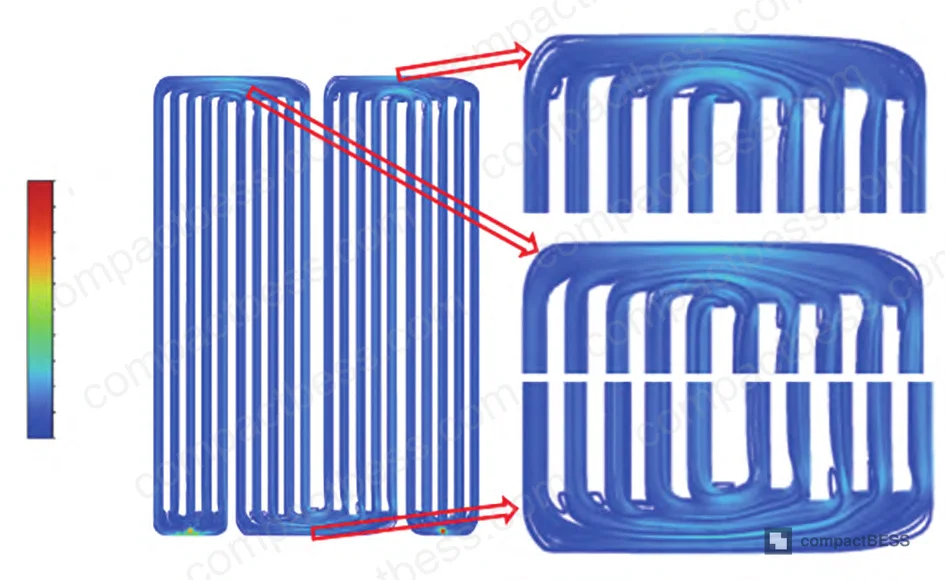
In supplier qualification, we’ve seen designs claim “optimized” serpentine geometry that show no evidence of manifold confluence analysis — just symmetric channel widths throughout. That approach leaves 30–40% of achievable resistance reduction on the table. Three of six sample cooling plates evaluated in one sourcing cycle had this problem, with measured flow resistance values clustering around 1,050–1,200 Pa when suppliers had quoted sub-800 Pa performance.
Most procurement teams don’t realize that serpentine plate optimization standards in industrial BESS applications now differentiate between bulk channel design and manifold zone design as separate engineering deliverables — and many suppliers are only capable of delivering the former.
LFP Cell Thermal Behavior and Pack-Level Temperature Management #
A few things about this specific 280 Ah prismatic LFP cell configuration are worth flagging for buyers sourcing 40–50 kWh stationary packs.
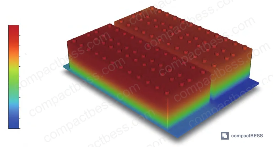
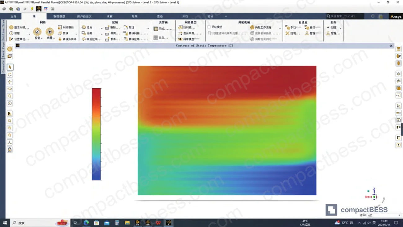
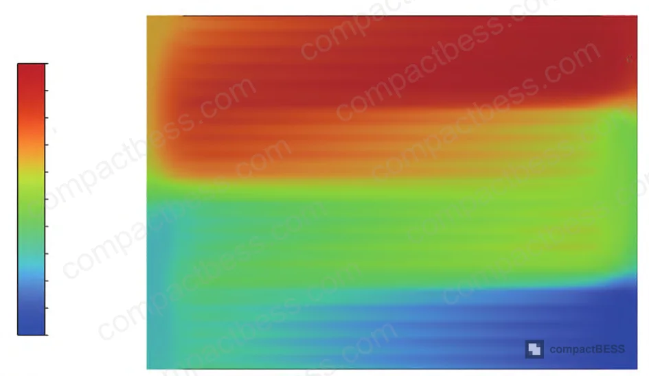
First, the anisotropic conductivity — 2.5 W/(m·K) cross-lamination vs. 12 W/(m·K) along the laminate plane — means bottom-mounted cooling plates face a fundamentally longer conduction path than side-mounted designs. The data shows the 5-channel bottom-plate configuration still achieves 38.4 °C maximum pack temperature and 2.1 °C inter-cell differential, which is within the acceptable operating window (20–40 °C) and well under the 5 °C inter-cell limit. But the temperature distribution map clearly shows the top half of the pack running warmer — because heat must travel the full vertical height of the 208 mm cell before reaching the bottom-mounted plate.
At 0.03 kg/s inlet flow, maximum temperature approaches 40 °C — which is exactly at the operational ceiling. At 0.05 kg/s, there’s comfortable margin. This is critical context for buyers specifying systems that may operate in elevated ambient environments: the cooling flow rate spec is not conservative headroom, it’s a functional boundary condition.
The inlet-to-outlet temperature rise across the cooling plate was approximately 3.8 °C under 1C discharge conditions. That differential matters for inter-module temperature balance in multi-plate configurations — cells near the coolant outlet run consistently warmer than those near the inlet, which accelerates differential aging if pack design doesn’t account for it.
For compliance reference, thermal management requirements for stationary BESS are addressed in IEC 62619:2022 (safety for secondary lithium cells in stationary applications), while transport certification thermal requirements fall under UN 38.3. Buyers sourcing for North American markets should additionally reference UL 9540 for full system evaluation, which includes thermal runaway propagation testing that indirectly validates pack-level thermal management adequacy.
For deeper reference on LFP chemistry behavior under thermal stress, see our lithium-ion vs LFP chemistry guide and cycle life and degradation analysis.
Practical Guidance for Buyers #
If you’re sourcing liquid-cooled battery packs for stationary BESS applications in the 40–60 kWh range, here’s the procurement hierarchy that this data supports.
First, stop treating channel count as a differentiating specification. The thermal output difference between a 5-channel and an 8-channel serpentine plate is negligible — under 0.2 °C in maximum temperature. What you’re actually buying is a pump load specification. Every 100 Pa of unnecessary flow resistance has a real operating cost over a 10+ year product lifetime.
Second, demand manifold geometry documentation separately from channel geometry. Any supplier who hands you a channel width spec but can’t articulate their confluence zone design has not optimized their plate — they’ve just drawn straight channels. The 41.8% resistance reduction achieved through manifold optimization here came entirely from that zone, not from changing channel count or width.
Third, the 2.1 °C inter-cell differential is achievable and should be your benchmark. IEC 62619 doesn’t specify a hard inter-cell delta, but industry practice treats 5 °C as the outer limit for LFP pack longevity. Hitting 2.1 °C means you have margin. Anything above 3.5 °C from a sample test warrants investigation.
Fourth, verify coolant flow rate spec against ambient operating envelope. The boundary between safe and marginal operation in this data set sits at 0.05 kg/s. If your deployment site runs ambient above 35 °C, that margin compresses fast.
At CompactBESS, we work directly with verified Chinese manufacturers of liquid-cooled BESS modules and can connect you with suppliers who carry CFD-validated thermal designs with full documentation packages — not just spec sheets. If your sourcing requirement includes geometric validation data or flow resistance test reports, we can screen for that during supplier matching.
Need help identifying qualified suppliers for liquid-cooled BESS pack assemblies? Talk to our sourcing team →
Supplier Qualification Questions #
- What is the measured flow resistance (Pa) of your standard serpentine cooling plate design at 0.05 kg/s coolant inlet flow, and can you provide the CFD validation report showing the comparison between surrogate model prediction and Fluent verification results — with error margin documented?
- What is your confluence zone (manifold turn) geometry design basis? Specifically, what are the inter-channel gap dimensions at each manifold turn, and have they been optimized separately from bulk channel width to suppress vortex formation — targeting sub-700 Pa total flow resistance?
- At 1C discharge with 25 °C initial temperature and 0.05 kg/s coolant flow, what is your documented inter-cell maximum temperature differential, and does it remain at or below 2.1 °C across the full module with 48 cells configured in two modules?
- What is the inlet-to-outlet coolant temperature rise across your cooling plate under rated heat load, and is your design validated to hold maximum pack temperature below 39 °C at the 0.05 kg/s flow condition with 17 W per cell heat generation?
- What is the anisotropic thermal conductivity specification of the prismatic cells your cooling plate was designed for — specifically the cross-lamination (x-direction) vs. along-laminate (y/z-direction) conductivity values — and does your plate placement geometry account for the resulting asymmetric heat path?
Sourcing Checklist #
- [ ] Supplier provides CFD simulation report with documented mesh independence verification (mesh count ≥17,970,000 elements or equivalent grid convergence evidence)
- [ ] Flow resistance at 0.05 kg/s inlet flow is confirmed ≤650 Pa via Fluent or equivalent solver validation, with surrogate model error margin stated below 10%
- [ ] Maximum pack temperature is verified ≤39 °C under 1C discharge (17 W/cell heat load) at 25 °C initial conditions per IEC 62619:2022 thermal operating limits
- [ ] Inter-cell temperature differential is confirmed ≤2.1 °C under rated discharge, with temperature uniformity map included in test documentation
- [ ] Cooling plate dimensional spec confirms: coolant port diameter ≥12 mm, channel width ≥20 mm, plate thickness ≥6 mm, inlet/outlet on same side for ease of manifold routing
- [ ] Surrogate model R² values for both thermal (≥0.91) and flow resistance (≥0.98) objectives are documented, confirming optimization was based on statistically valid sampling
- [ ] Thermal interface material (thermal conductive adhesive) between cells and cooling plate is specified with conductivity value; assembly method (bonding + metal banding) is documented
- [ ] System-level safety certification documentation covers thermal runaway propagation per UL 9540A and transport compliance per UN 38.3
Key Specifications Table #
| Parameter | Recommended Value | Verification Method |
|---|---|---|
| Maximum pack temperature (1C discharge) | ≤39 °C | CFD simulation (Fluent/equivalent) validated against physical thermocouple data; boundary: 25 °C initial temp, 17 W/cell heat load |
| Inter-cell temperature differential | ≤2.1 °C | Thermal simulation with full 48-cell pack model; confirm via temperature nephogram across both modules |
| Cooling plate flow resistance | ≤650 Pa at 0.05 kg/s | Pressure drop measurement across inlet/outlet ports; cross-check against CFD prediction with <10% error tolerance |
| Coolant inlet flow rate | 0.05 kg/s (minimum) | Flow meter measurement at pump outlet; note that 0.03 kg/s brings max temp to ~40 °C — insufficient margin |
| Manifold confluence zone geometry | Outer gap ≥ inner gap; X5, X6 ≥ 56 mm | Dimensional inspection of plate tooling drawing; verify asymmetric “crescent” profile in junction zones |
| Cell thermal conductivity (x-direction) | 2.5 W/(m·K) minimum confirmation | Supplier cell spec sheet; cross-lamination conductivity drives heat path length for bottom-plate configurations |
| Coolant inlet-to-outlet temperature rise | ≤3.8 °C under rated load | Thermocouple measurement at inlet and outlet ports during 1C discharge test |
| Response surface model accuracy (R²) | ≥0.98 for flow resistance prediction | Surrogate model documentation; R² < 0.90 indicates optimization was not statistically reliable |
Can’t find a supplier meeting these specs? Submit your requirements and we’ll match you within 48 hours.
Frequently Asked Questions #
Q1: Does increasing the number of cooling channels always improve thermal performance in serpentine liquid cooling plates?
No — and this is one of the most common misconceptions in pack thermal design. Across six configurations from 3 to 8 channels tested on a 43 kWh LFP pack, the difference in maximum temperature between channel counts was less than 0.2 °C. The variable that actually changes meaningfully is flow resistance, which decreases as channel count increases because coolant velocity per channel drops. Specifying a higher channel count to “improve cooling” without addressing manifold geometry will get you marginal gains at best.
Q2: What is the practical operating risk if coolant flow rate drops below 0.05 kg/s?
At 0.03 kg/s, maximum pack temperature approaches 40 °C — the functional ceiling for normal LFP pack operation. There is essentially no thermal margin remaining under those conditions. Any ambient temperature above 25 °C, any degradation in pump output, or any increase in discharge rate would push the system into the risk zone. Specify 0.05 kg/s as the minimum flow rate in your procurement standard and verify it as a commissioning parameter.
Q3: Why was the 5-channel design chosen for optimization rather than the 8-channel design, which showed lower flow resistance?
The 8-channel plate has lower baseline flow resistance but greater manufacturing complexity — more channel tooling, more potential leak points, tighter tolerances on channel uniformity. The 5-channel design offered a better balance: its optimized version achieved 640.6 Pa, which is lower than the unoptimized 8-channel baseline. The key insight is that manifold optimization extracts more resistance reduction than adding channels does — with less manufacturing complexity added.
Q4: How does the anisotropic thermal conductivity of prismatic LFP cells affect cooling plate placement decisions?
Prismatic LFP cells conduct heat roughly 4.8× more efficiently along the laminate plane (12 W/(m·K)) than across it (2.5 W/(m·K)). Bottom-mounted cooling plates require heat to travel the full cell height in the low-conductivity direction. The result, visible in the temperature distribution maps, is that the upper half of the pack consistently runs warmer. This is a structural limitation of bottom-plate cooling — not a failure, but a known behavior that should inform your inter-module temperature management strategy and accelerated aging expectations for upper-stack cells.
Q5: What certifications should a liquid-cooled BESS pack carry for export to European or North American markets?
At minimum: IEC 62619:2022 for stationary application safety, en” target=”_blank” rel=”nofollow noopener”>CE marking for EU market entry. North American deployments increasingly require UL 9540 system-level certification. Beyond certifications, request the supplier’s thermal runaway propagation test data — a pack that passes IEC 62619 thermal limits in normal operation but has not been tested for propagation behavior is only half-qualified for commercial deployment. For a full certification roadmap, see our CE, FCC, and RoHS compliance guide.
Published by compactbess.com Technical Team | Request a sourcing quote
Data source: Flow Resistance Optimization and Thermal Management Analysis of Multi-Channel Serpentine Liquid Cooling Plates for Large-Format LFP Battery Packs, J. Xin et al., Journal of the Electrochemical Society, 2025


