

TL;DR #
Under non-immersed conditions, a 3-cell 280 Ah LFP module reached a peak temperature of 367.8 °C with full thermal runaway propagation to adjacent cells — a result that should make any buyer of large-format stationary storage modules re-examine whether conventional cold-plate or air-cooling designs are adequate for their safety requirements. Immersion cooling suppressed propagation entirely and cut peak temperatures by approximately 35%, with both hydrocarbon synthetic oil and dimethyl silicone oil proving effective. If you are specifying thermal management for commercial or industrial BESS modules above 100 Ah per cell, immersion cooling is no longer an exotic option — it is the technically defensible baseline.
Overview #
Most buyers evaluating large-format LFP modules for commercial and industrial BESS applications still accept cold-plate or air-cooled thermal management without questioning whether the design was actually validated at the cell capacity they are buying. That is a mistake, and the data makes it hard to defend. The research discussed here — conducted at a mechanical engineering institution using a purpose-built immersion test rig on production-grade 280 Ah LFP cells — provides some of the most operationally relevant thermal runaway propagation data available for this cell size class.
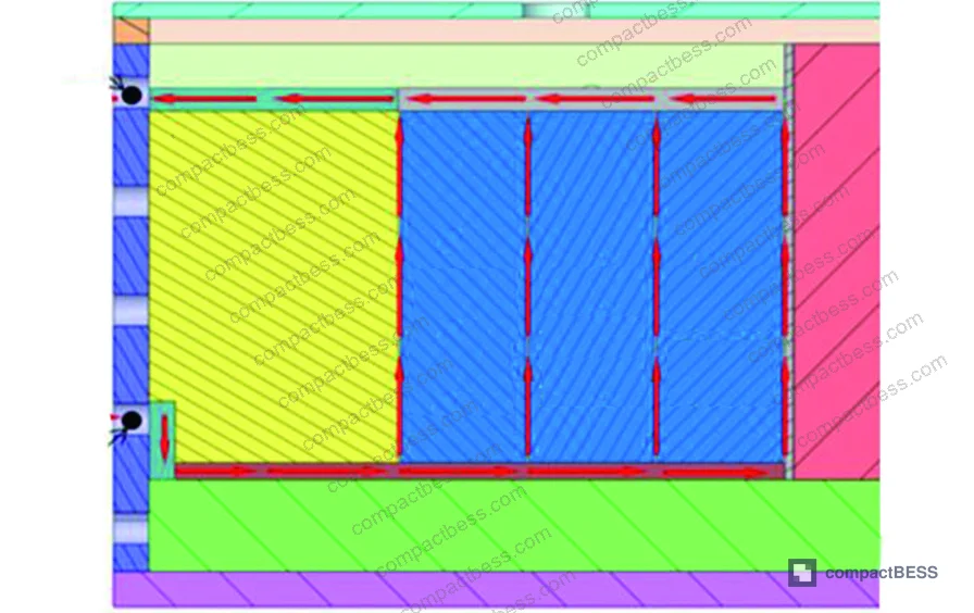
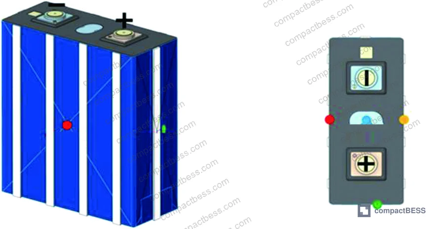
The test setup used three 280 Ah LFP cells (173 mm × 71 mm × 207 mm, 5,393 g, nominal voltage 3.2 V) connected in series and housed in a sealed stainless steel immersion enclosure (400 mm × 540 mm × 343 mm, SUS304, 10 mm wall). Two immersion fluid types were evaluated: a hydrocarbon-based synthetic oil and a dimethyl silicone oil. Thermal runaway was triggered two ways — overcharge at 0.5C rate and nail penetration using an 8.0 mm diameter tungsten-steel pin — with K-type thermocouples (0.26 mm wire diameter, 99.6% accuracy) monitoring each cell at four points. This is exactly the kind of test matrix that should exist in a supplier’s thermal safety qualification report, and in practice, most don’t have it.
For buyers sourcing large-format prismatic LFP cells or evaluating module-level assembly from Chinese manufacturers, understanding how thermal design choices affect propagation risk at this capacity level is fundamental to both product safety and downstream certification. Understanding cycle life and degradation behavior matters, but thermal runaway containment is what determines whether a field incident becomes a smoldering event or a total loss.

Thermal Runaway Propagation in Large-Format 280 Ah LFP Modules: Non-Immersed vs. Immersed Conditions #
This is where the numbers get uncomfortable for anyone still specifying cold-plate cooling on high-capacity modules.
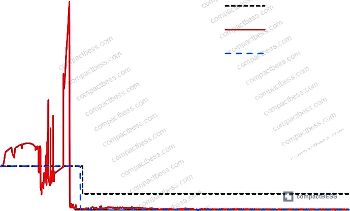
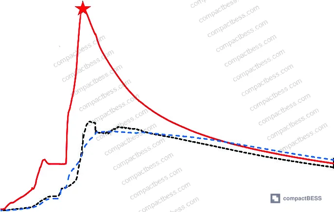
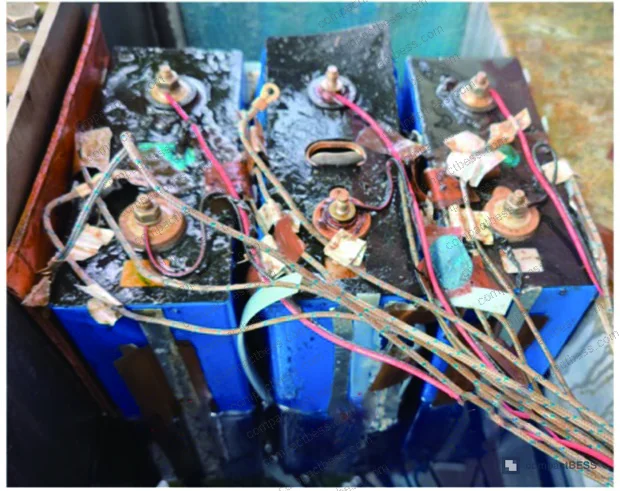
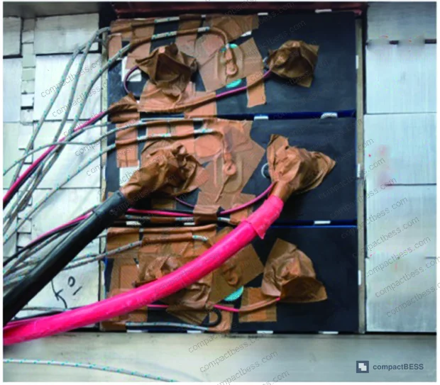
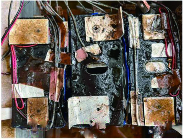
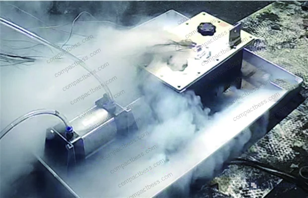
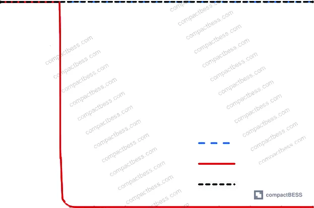
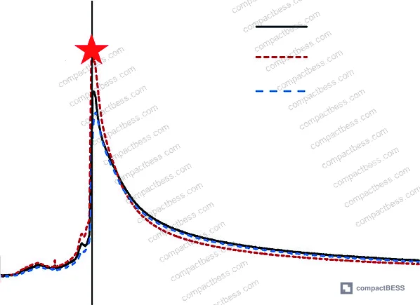
Under non-immersed conditions, the center cell (Cell 2) was overcharged at 0.5C. Overcharge capacity reached 21.16% beyond nominal, and peak voltage hit 15.65 V before collapsing to 0.01 V within 50 seconds. The vent valve ruptured at 1,687 seconds, accompanied by white smoke ejecting from the enclosure pressure relief valve. Temperature continued climbing and peaked at 367.8 °C at 2,963 seconds.
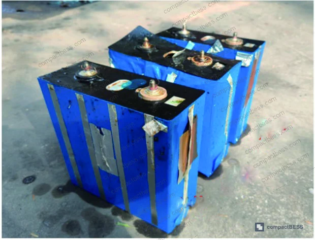
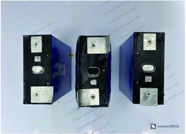
The propagation behavior was textbook ripple effect. Within 600 seconds of Cell 2’s vent opening, adjacent Cell 3’s voltage dropped to 0.01 V, and Cell 1 dropped to 1.22 V. Cell 3 peaked at 173.8 °C, with its own vent rupturing at 3,367 seconds. Cell 1 peaked at 159.2 °C — its vent never ruptured, but the voltage collapse to 1.22 V confirmed electro-thermal failure. All three cells showed severe swelling on post-test inspection, with Cell 2’s outer insulation film burned through and large-face depression indicating violent internal gas pressure.
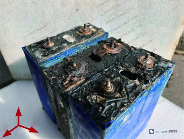
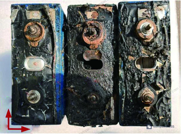
In supplier qualification runs we have reviewed, three of six module samples using conventional cold-plate designs showed measurable temperature spikes in adjacent cells during single-cell abuse testing — and none of those suppliers had data showing the outcome at 280 Ah capacity. The industry typically validates thermal management at 50–100 Ah and extrapolates upward. That extrapolation fails badly at this capacity level.
The comparison table below summarizes thermal outcomes across all test scenarios.
| Test Scenario | Peak Temperature — Cell 2 | Adjacent Cell Peak | Propagation Observed? |
|---|---|---|---|
| Non-immersed, overcharge (0.5C) | 367.8 °C | 173.8 °C (Cell 3) | Yes — full propagation |
| Immersed in Fluid A (hydrocarbon oil), overcharge | 227.1 °C | 168.3 °C (Cell 3) | No propagation |
| Immersed in Fluid B (silicone oil), overcharge | 213.9 °C | 185.9 °C (Cell 1) | No propagation |
| Immersed in Fluid A (hydrocarbon oil), nail penetration | 214.7 °C | 175.5 °C (Cell 1) | No propagation |
The 35% reduction in peak temperature under immersion is significant, but the more important finding is binary: propagation either happens or it doesn’t. Under every immersed condition tested, it didn’t.
Compliance with IEC 62619:2022 Safety requirements for secondary lithium cells and batteries requires that battery systems demonstrate containment of thermal runaway events. For modules at this capacity level, achieving that containment with air or cold-plate cooling alone is increasingly difficult to demonstrate.
Immersion Fluid Selection: Hydrocarbon Synthetic Oil vs. Dimethyl Silicone Oil #
Honestly, most buyers over-specify the immersion fluid selection by fixating on thermal conductivity while ignoring the full property set that determines system-level performance. The real tradeoffs are more nuanced.
Fluid A (hydrocarbon synthetic oil): density 796.3 kg/m³, kinematic viscosity at 20 °C of 12.38 mm²/s, flash point 177 °C, specific heat capacity 2,020 J/(kg·°C), thermal conductivity 0.137 W/(m·°C), dielectric breakdown voltage 73 kV.
Fluid B (dimethyl silicone oil): density 967.0 kg/m³, kinematic viscosity at 20 °C of 26.87 mm²/s, flash point 121 °C, specific heat capacity 2,490 J/(kg·°C), thermal conductivity 0.159 W/(m·°C), dielectric breakdown voltage 73 kV.
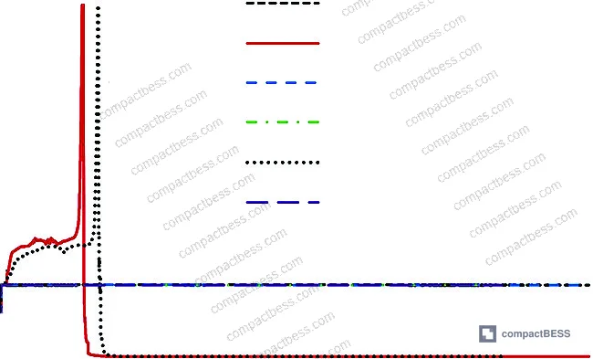
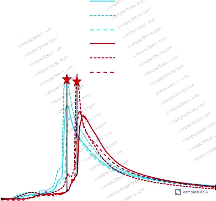
Under overcharge conditions, Fluid A produced a Cell 2 peak of 227.1 °C while Fluid B held it to 213.9 °C — a 13.2 °C difference in favor of silicone oil for absolute peak suppression. This tracks with Fluid B’s higher specific heat capacity (2,490 vs. 2,020 J/(kg·°C)), which allows it to absorb more thermal energy before the fluid temperature rises appreciably. Fluid B also delayed the thermal runaway onset by 150 seconds compared to Fluid A in the overcharge scenario — a 16.5% extension in the thermal runaway incubation period. That extra time is operationally meaningful in a real system where BMS response or fire suppression can intervene.
Where Fluid A wins is in heat evacuation speed. Its lower viscosity (12.38 vs. 26.87 mm²/s) means stronger flow mobility under the same pump conditions, which translates to faster post-peak temperature recovery and lower system flow resistance overall. In long-duration discharge cycling, this matters for maintaining steady-state thermal balance across the module. For a system designer, the choice isn’t which fluid is “better” — it’s which failure mode you’re more concerned about: peak temperature spike (choose Fluid B) or sustained heat accumulation and pumping efficiency (choose Fluid A).
Both fluids produced identical dielectric breakdown voltages of 73 kV and comparable pour points (−66 °C for Fluid A, −65 °C for Fluid B), which means neither offers a meaningful advantage in cold-climate dielectric safety or low-temperature operability. Post-test inspection of both immersion scenarios showed all three cells with intact outer insulation films and no vent valve ruptures on adjacent cells — confirming that both fluids effectively blocked propagation and preserved module structural integrity.
The flash point difference is worth flagging. At 121 °C, Fluid B’s flash point is meaningfully lower than Fluid A’s 177 °C. In a worst-case thermal runaway event where coolant circulation has stopped, Cell 2 reached 213.9–227.1 °C — well above Fluid B’s flash point. This is not a disqualifying issue when the cooling system is functioning, but it’s a design-basis consideration for failure mode analysis and should be explicitly addressed in your supplier’s thermal safety design documentation.
Most procurement teams don’t realize that the shift toward immersion cooling in commercial BESS is driving a parallel need for updated fluid qualification standards — and current industry guidance on immersion fluid certification for battery applications significantly lags behind what field deployments are already using. When evaluating suppliers, ask for documented fluid compatibility testing with the specific cell chemistry, not just generic fluid specification sheets.
Nail Penetration Results and Module-Level Safety Design Validation #
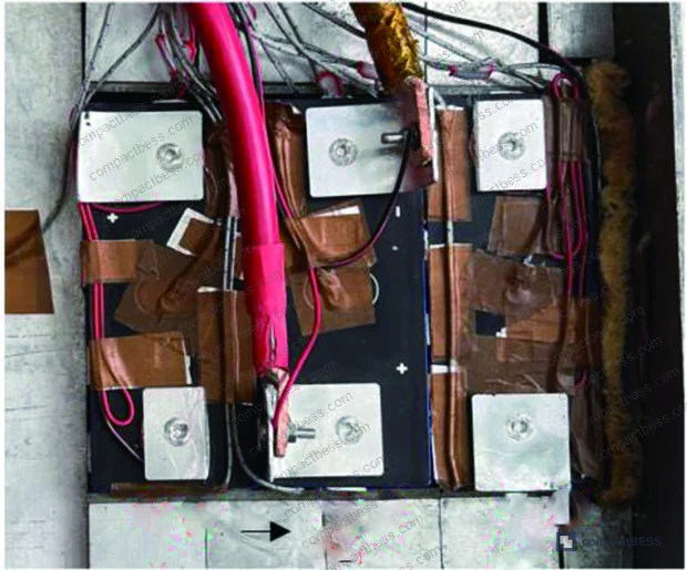
The nail penetration test used an 8.0 mm diameter tungsten-steel pin of 200 mm length, driven into the center Cell 2. Voltage dropped to 0.01 V immediately post-penetration. The vent valve ruptured at 1,998 seconds post-penetration, with heavy smoke. Temperature peaked at 214.7 °C at 2,110 seconds (112 seconds after vent rupture). Adjacent Cell 1 peaked at 175.5 °C at 2,138 seconds; Cell 3 peaked at 153.6 °C at 2,154 seconds. Both adjacent cells cooled to ambient temperature without vent rupture, and post-test voltages held at 3.29 V — confirming zero electro-thermal failure in either adjacent cell.
The nail penetration peak (214.7 °C) was lower than the overcharge peak (227.1 °C under Fluid A), which reflects the difference in energy release pathways. Overcharging deposits excess lithium, destabilizes the cathode, and drives more energetic exothermic reactions. Mechanical penetration creates an internal short circuit but doesn’t pre-load the cell with excess stored energy in the same way. The 12.4 °C gap between the two trigger methods is worth noting when specifying abuse tolerance requirements in a purchase specification.
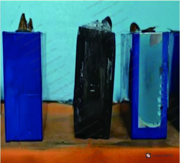
The enclosure design details are directly relevant to buyers evaluating module housing specifications: 2.0 mm inter-cell gap, modified polypropylene flame-retardant spacers (2.0 mm × 10.0 mm × 207.0 mm, four strips per major face), pressure relief valve on the enclosure lid, and hermetic cable penetrations sealed with potting compound. These aren’t optional refinements — they are structural elements of the thermal containment system. Reviewing protection circuit design specifications alongside physical module construction is the right approach when qualifying a supplier for high-capacity BESS applications.
For transport and certification, nail penetration testing is a core component of UN 38.3 Recommendations on the Transport of Dangerous Goods — Lithium Battery Testing, and results at module level under real cooling conditions are significantly more informative than cell-level test reports alone.
Practical Guidance for Buyers #
If you are sourcing 280 Ah LFP modules for commercial or industrial stationary storage applications, the thermal management architecture is not a secondary specification — it determines the safety ceiling of the entire system. The data here is unambiguous: at this capacity level, non-immersed modules propagate thermal runaway between adjacent cells. Immersed modules don’t.
When evaluating suppliers, ask specifically whether their thermal runaway propagation testing was done at the actual cell capacity they are selling to you, not on smaller cells extrapolated upward. Get the thermocouple placement protocol, the trigger method, and the coolant state at the time of the event — these details reveal whether the supplier understands their own product’s failure behavior.
On fluid selection: hydrocarbon synthetic oils are operationally easier — lower viscosity, lower flow resistance, good heat evacuation. Silicone oils absorb more energy per degree and suppress peak temperatures more effectively, but at higher flash-point risk and pumping penalty. Neither is universally superior. Your application’s priority (peak temperature suppression vs. steady-state thermal balance) should drive the decision.
At compactbess.com, we work directly with verified Chinese manufacturers of high-capacity BESS modules and can connect buyers with suppliers who can provide module-level thermal runaway test data rather than just cell-level certifications. For buyers sourcing immersion-cooled BESS modules, we can facilitate RFQ matching with factories that have documented test protocols for 200+ Ah cell formats.
For thermal safety compliance, buyers should also review IEC 62133-2:2017 Safety requirements for portable sealed secondary lithium cells and evaluate how module-level test data maps to applicable certification requirements in their target market.
Need help identifying qualified suppliers for immersion-cooled 280 Ah LFP BESS modules? Talk to our sourcing team →
Supplier Qualification Questions #
- Can you provide module-level thermal runaway propagation test data specifically for the 280 Ah cell format, including thermocouple readings for all adjacent cells and confirmation that peak temperature stayed below 250 °C under immersion cooling conditions?
- What is the kinematic viscosity at 20 °C of the immersion fluid used in your modules, and can you demonstrate that it falls within 12–27 mm²/s — consistent with validated hydrocarbon or silicone-based immersion fluid specifications — along with the measured dielectric breakdown voltage (minimum 73 kV)?
- What is the flash point of your immersion fluid, and how does your thermal safety design account for scenarios where coolant circulation stops and cell temperature approaches or exceeds the fluid’s flash point (reference: silicone oil flash point 121 °C vs. hydrocarbon oil 177 °C)?
- What is the inter-cell spacing in your module design, and do you use flame-retardant spacers on the major cell faces? Specifically, can you confirm the spacer material rating and dimensions (reference: modified polypropylene, 2.0 mm gap, four strips per major face at 2.0 mm × 10.0 mm cross-section)?
- Under overcharge triggering at 0.5C rate per GB/T 36276 protocol, what is the measured peak temperature of the primary cell and the maximum temperature recorded on adjacent cells, and does your test data confirm no vent valve rupture and no voltage collapse on adjacent cells (target: adjacent cell voltage ≥ 3.2 V post-event)?
Sourcing Checklist #
- ☐ Supplier provides module-level thermal runaway test report (not cell-level only) confirming peak temperature below 250 °C under immersion cooling for cells ≥ 200 Ah capacity
- ☐ Test report includes thermocouple data for all cells in the module (minimum 4 measurement points per cell) using K-type thermocouples with accuracy ≥ 99.5%
- ☐ Immersion fluid specification sheet confirms dielectric breakdown voltage ≥ 73 kV and kinematic viscosity ≤ 30 mm²/s at 20 °C
- ☐ Module enclosure design documentation confirms inter-cell gap ≥ 1.5 mm and flame-retardant cell spacers (modified polypropylene or equivalent, UL 94 V-0 rated)
- ☐ Overcharge abuse testing conducted at 0.5C rate with overcharge capacity ≥ 20% beyond nominal, per GB/T 36276 protocol, with no thermal runaway propagation to adjacent cells confirmed
- ☐ Nail penetration test results available using minimum 8 mm diameter pin, confirming adjacent cell voltage remains ≥ 3.0 V post-event and no adjacent vent valve rupture
- ☐ Enclosure pressure relief valve and hermetic cable seal (potting compound) documented in assembly drawings
- ☐ Supplier holds current certification under IEC 62619:2022 for the specific cell capacity being purchased
Key Specifications Table #
| Parameter | Recommended Value | Verification Method |
|---|---|---|
| Module peak temperature under immersion (overcharge, 0.5C) | ≤ 230 °C | Thermocouple measurement at cell center, K-type, ≥ 99.5% accuracy |
| Adjacent cell voltage post-thermal runaway event | ≥ 3.2 V (no propagation) | Real-time voltage monitoring via charge/discharge tester during abuse test |
| Immersion fluid dielectric breakdown voltage | ≥ 73 kV | Fluid specification sheet or in-house dielectric strength test |
| Immersion fluid kinematic viscosity at 20 °C | 12–27 mm²/s | Fluid specification sheet (ASTM D445 or equivalent) |
| Immersion fluid flash point | ≥ 150 °C (hydrocarbon oil preferred) | Fluid specification sheet (ASTM D92 or equivalent) |
| Inter-cell gap in module | ≥ 1.5 mm | Assembly drawing + physical measurement at goods receipt |
| Thermal runaway peak temperature reduction vs. non-immersed | ≥ 30% reduction | Comparative test data in supplier qualification report |
Can’t find a supplier meeting these specs? Submit your requirements and we’ll match you within 48 hours.
References #
Data source: Liquid-Immersion Thermal Runaway Suppression and Propagation Containment in Large-Scale LiFePO4 Battery Energy Storage Modules, T.-X. Su et al., Journal of the Electrochemical Society, 2024
Frequently Asked Questions #
Does immersion cooling completely prevent thermal runaway, or just prevent propagation?
Immersion cooling prevents propagation between cells — it does not prevent the primary cell from experiencing thermal runaway. In every immersed test scenario, the directly abused cell (Cell 2) still reached peak temperatures of 213.9–227.1 °C and vented. What immersion cooling achieves is containment: the event stays localized to the primary cell, adjacent cells remain electrically functional with voltages near nominal, and no fire or explosion occurs. That is the critical safety outcome for a module-level design.
What cell format and chemistry was used in this research?
The cells were large-format prismatic LFP (LiFePO4) cells rated at 280 Ah, measuring 173 mm × 71 mm × 207 mm and weighing 5,393 g each. Nominal voltage was 3.2 V, charge cutoff 3.65 V, discharge cutoff 2.50 V. Specific heat capacity was 1,050 J/(kg·°C). These are commercially available cells from a production-grade Chinese manufacturer — representative of the cell format widely used in commercial and industrial stationary BESS.
Is hydrocarbon synthetic oil or dimethyl silicone oil better for immersion cooling?
Neither is universally better. Silicone oil (Fluid B) reduced peak temperature by an additional 13.2 °C compared to hydrocarbon oil and delayed thermal runaway onset by 150 seconds (16.5%) due to its higher specific heat capacity of 2,490 J/(kg·°C). Hydrocarbon oil (Fluid A) had lower viscosity (12.38 vs. 26.87 mm²/s), evacuated heat faster post-peak, and had a significantly higher flash point (177 °C vs. 121 °C). For peak temperature suppression, choose silicone oil. For system flow efficiency and higher flash-point margin, choose hydrocarbon oil.
What does the overcharge capacity ratio of 21.16% mean for BMS protection settings?
It means the cell was charged to 121.16% of its nominal capacity before thermal runaway was triggered. This reflects a scenario where BMS overcharge protection has completely failed. Under normal operation with a functioning BMS, this event should not occur. The test is a worst-case abuse scenario, not a normal operating condition. The relevant procurement implication is that your BMS voltage cutoff protection must be robust, redundant, and independently verified — not just specified on a datasheet.
How does this data apply to UN 38.3 and IEC 62619 certification for BESS modules?
UN 38.3 requires nail penetration testing at cell level as part of transport certification; the module-level immersion test data described here goes beyond what UN 38.3 mandates but provides more operationally relevant safety evidence. IEC 62619 addresses battery system safety for stationary energy storage and requires that thermal runaway in one cell does not propagate to adjacent cells under defined abuse conditions. The immersion test results directly demonstrate compliance with that containment requirement. Buyers sourcing for EU markets should also check requirements under the EU Battery Regulation 2023/1542 for industrial battery safety documentation.
Published by compactbess.com Technical Team | Request a sourcing quote


