

TL;DR #
A perfluoropolyether (PFPE) phase-change immersion cooling system tested on 100 Ah prismatic lithium cells held maximum module temperature below 45 °C and internal temperature rise under 7 °C across both 1C and 4C discharge rates — compared to a 20 °C rise under natural air cooling at 4C. For buyers specifying battery packs for high-rate cycling applications, this data makes a strong case for evaluating immersion-cooled module designs over conventional cold-plate architectures. Before issuing an RFQ for any pack rated above 2C continuous discharge, ask suppliers directly which thermal management topology they use and request measured temperature uniformity data, not just maximum temperature claims.
Overview #
Most buyers treat thermal management as an afterthought — something the BMS handles, or a note in the datasheet saying “operating temperature: 0–45 °C.” That framing gets expensive fast, particularly when cells are being pushed at 3C or higher in stationary storage or portable power applications. The more meaningful question is: what is the temperature delta across the module during high-rate discharge, and how does that delta evolve over a full discharge cycle?
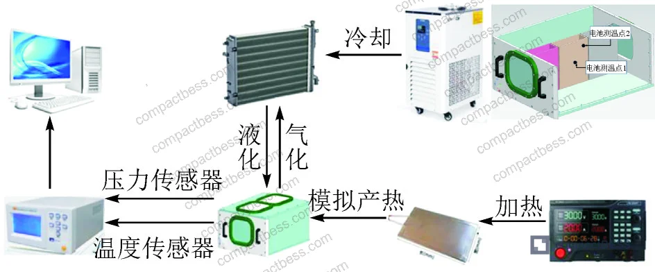
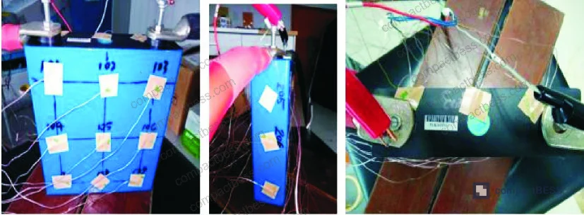
Researchers at a university-affiliated energy storage technology innovation center constructed a closed-loop experimental platform using 100 Ah prismatic lithium cells fully submerged in PFPE fluid, with a condenser, circulation pump, vacuum pump, and 15-point thermocouple network to monitor cell surface temperatures across multiple discharge conditions. The platform used resistive heaters to simulate cell heat generation, and varied discharge rate between 1C and 4C to capture both steady-state and high-stress thermal behavior. Results were cross-validated with infrared thermal imaging of the battery enclosure interior.
This is not a theoretical study. The thermal performance figures cited throughout this article come from a physically constructed test rig, and the comparison between natural cooling and immersion cooling was made on identical cell hardware under identical discharge protocols.
For buyers evaluating cell formats and form factors in the context of thermal integration, understanding how cell geometry interacts with cooling topology is foundational to pack design decisions.
Thermal Performance of PFPE Immersion Cooling Across Discharge Rates #
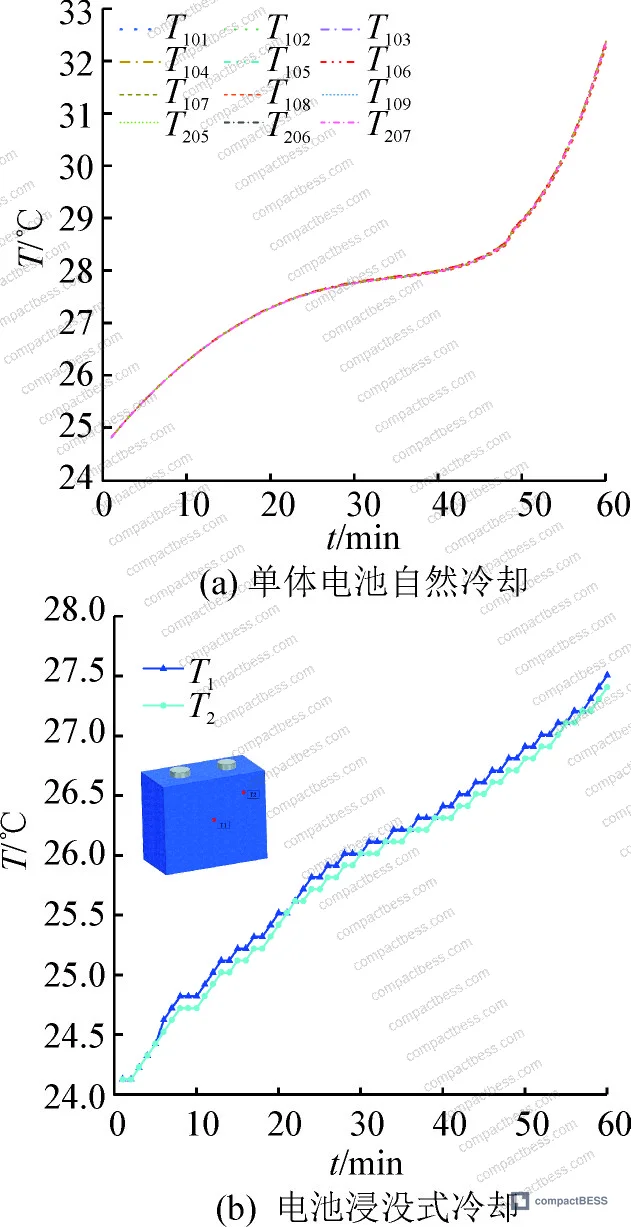
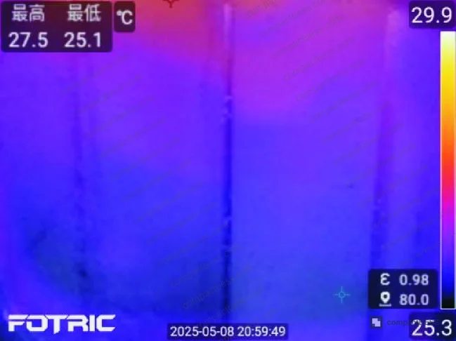
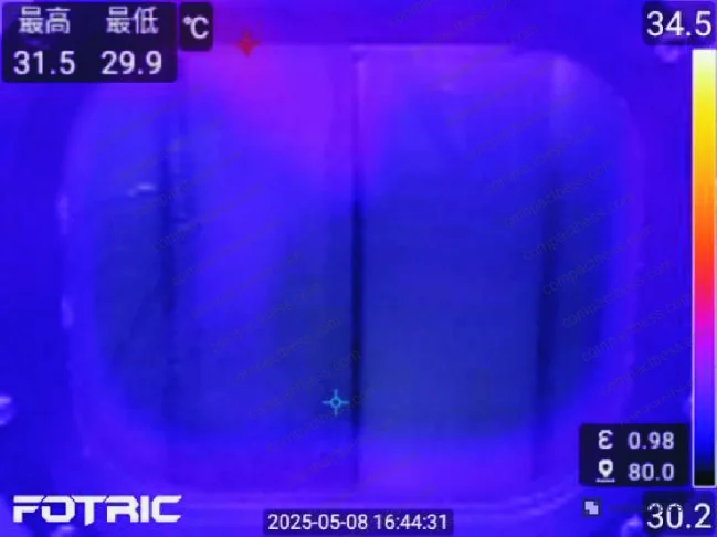
The core finding is straightforward: at 1C discharge, natural air cooling produced a cell surface temperature rise of approximately 8 °C. The PFPE immersion system reduced that to 3.5 °C. No phase change occurred during 1C discharge — the PFPE was operating purely in its single-phase sensible heat capacity regime, with the fluid boiling point not reached during the test run. Infrared imaging confirmed the maximum enclosure temperature at 27.5 °C, concentrated at the cell surface.
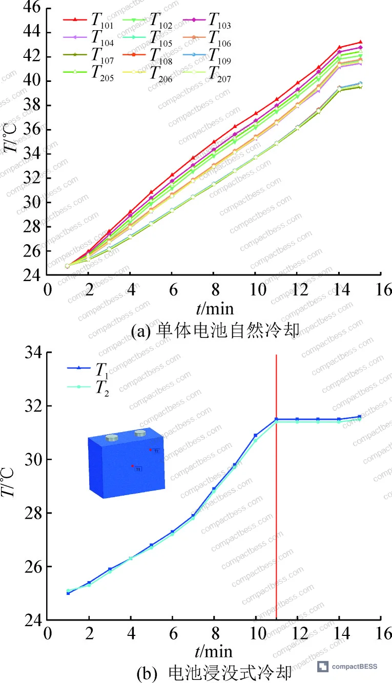
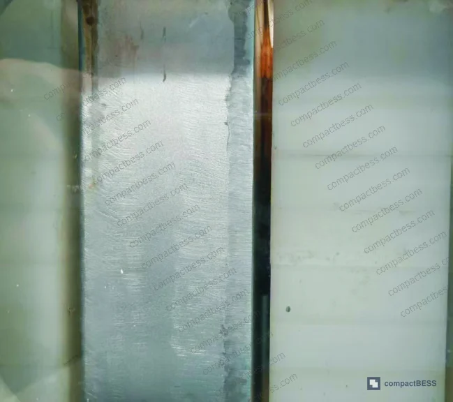
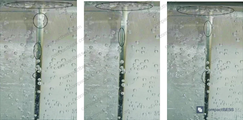
At 4C, the picture changes substantially. Natural air cooling produced a temperature rise of approximately 20 °C — which, starting from a 25 °C ambient, puts cells at 45 °C. That is the upper edge of the acceptable operating window for most lithium chemistries, and it leaves zero margin for elevated ambient conditions. Under the PFPE immersion system at 4C, the vacuum pump reduced the fluid boiling point to below the cell surface temperature, triggering vigorous boiling at around 11 minutes into the discharge cycle. Latent heat absorption during phase change held the cell temperature at approximately 31 °C, with infrared imaging showing a peak enclosure temperature of 31.5 °C. Maximum cell surface temperature rise was 6 °C at 4C — compared to 20 °C under natural convection.
The PFPE fluid properties driving these results are worth noting precisely:
- Boiling point at 101 kPa: 49 °C
- Density at 25 °C: 1.61 ± 0.03 g/mL
- Kinematic viscosity at 40 °C: 0.35 mm²/s
- Latent heat of vaporization: 98 J/g
- Thermal conductivity at 40 °C: 0.1038 W/(m·K)
- Specific heat capacity at 40 °C: 1.308 J/(g·K)
- Saturated vapor pressure at 25 °C: 34.204 kPa
- Dielectric strength (2.5 mm gap): 12.56 kV
- Pour point: below −118 °C
- Thermal decomposition temperature: above 300 °C
The dielectric strength figure is not incidental — it means the fluid can remain in direct contact with live cell terminals and bus connections without risk of short circuit. This eliminates the thermal interface material stack (cell → TIM → cold plate) entirely, removing multiple layers of contact resistance that limit conventional cold-plate performance.
| Cooling Method | Max Temp Rise at 1C | Max Temp Rise at 4C | Phase Change Active |
|---|---|---|---|
| Natural air convection | ~8 °C | ~20 °C | No |
| PFPE single-phase immersion | ~3.5 °C | N/A (transitions to phase-change) | No |
| PFPE phase-change immersion | ~3.5 °C | ~6 °C | Yes (at ~11 min into 4C discharge) |
Industry observation: most procurement teams don’t realize that IEC 62619:2022 — the primary safety standard for secondary lithium cells in energy storage applications — does not mandate a specific thermal management topology. It sets temperature limits, but leaves the engineering approach entirely to the manufacturer. That gap is where buyer specification discipline matters most.
Heat Generation Behavior of Lithium Cells Under Multi-Rate Discharge #
Understanding why immersion cooling outperforms at high rates requires looking at the heat generation profile, not just the temperature outcome.
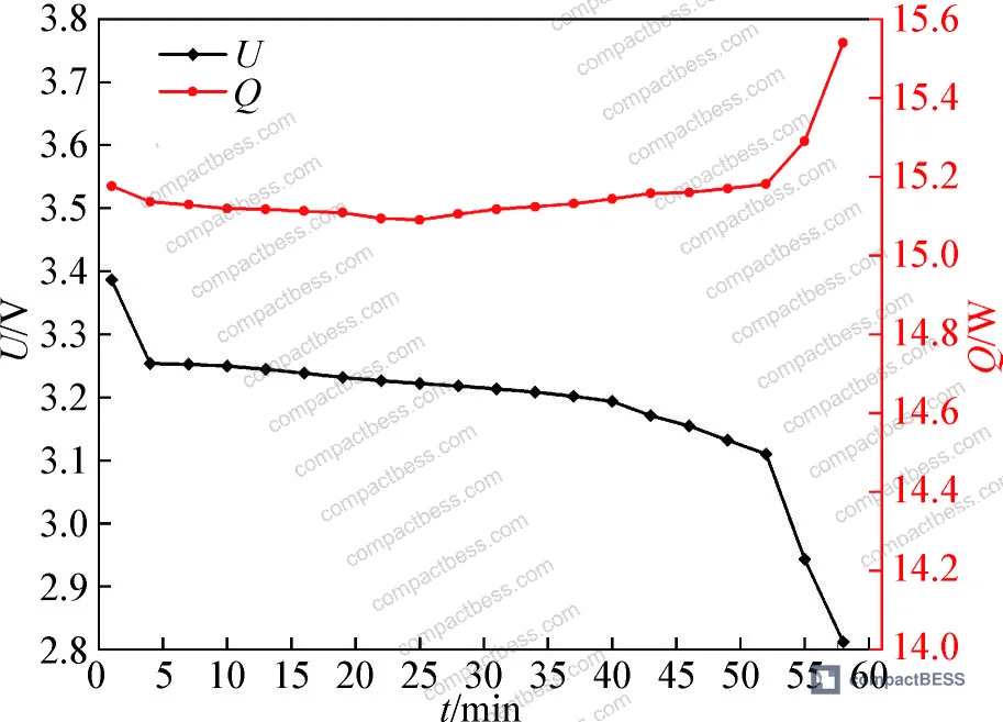
At 1C, the cell voltage drops gradually from an initial 3.39 V to approximately 3.1 V over the first 55 minutes, then falls sharply in the final discharge phase. Heat generation power follows a corresponding pattern: mildly elevated early on (dominated by ohmic and electrochemical reaction heat), stable through the mid-discharge plateau, then increasing sharply at end of discharge as voltage collapses and a larger fraction of chemical energy converts directly to heat rather than electrical work. The 1C profile is essentially manageable — internal polarization is weak, lithium-ion diffusion rates in electrode and electrolyte materials match electron transport, and the cell operates within a stable, predictable thermal envelope.
At 4C, the voltage profile begins at 3.4 V and declines continuously, with a sharp drop appearing near the 55-minute mark. The mechanism is different from 1C: at high discharge current, concentration polarization becomes severe at the electrode surface, charge transfer impedance rises significantly, and the effective discharge current may actually decrease in the late-discharge phase as internal resistance climbs. Early-phase heat generation is dominated by ohmic heating and is high; mid-to-late phase shows a temporary reduction as available chemical energy depletes; and end-of-discharge sees another spike as voltage collapses more steeply.
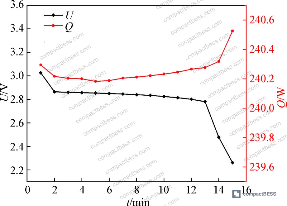
The practical consequence: at 4C, the heat generation rate is substantially higher than at 1C, the variation over the discharge cycle is more extreme, and the thermal management system must handle both the average load and the end-of-discharge spike. A cold-plate system that is adequately sized for the average load may be undersized for the terminal discharge phase — particularly under elevated ambient temperature conditions.
Honestly, most buyers over-specify battery capacity and under-specify thermal management. I’ve seen procurement briefs that list cell Ah capacity, cycle life target, and BMS protection parameters in precise detail, while the thermal architecture is described only as “liquid cooled” with no temperature uniformity requirement. That omission becomes a problem the first time the pack runs at rated C-rate in a 35 °C ambient.
The 100 Ah prismatic cells used in this test were specified at 134 × 220 × 27 mm, 2.3 kg, operating voltage 2.0–3.65 V, and maximum pulse discharge capability of 5C with a minimum allowed discharge voltage of 1.8 V. For buyers comparing pack designs, the cell format directly constrains cooling options — prismatic cells with flat surfaces are well-suited to immersion cooling, while cylindrical formats behave differently in the same fluid environment. See our cycle life and degradation resource for how operating temperature range affects long-term capacity retention.
System-Level Design and Operational Constraints of Phase-Change Immersion #
The closed-loop PFPE system described here operates on a vaporization-condensation cycle. When the battery enclosure reaches the PFPE boiling point (adjustable via vacuum pump control), fluid at the cell surface vaporizes, carrying latent heat into the vapor phase. Vapor travels through dedicated gas-phase piping to a condenser, where it reliquefies and returns to the enclosure via a liquid return line. The vacuum pump enables dynamic control of the system pressure, which directly adjusts the PFPE boiling point — allowing the thermal management system to adapt its response to changing heat generation intensity.
This design addresses a real limitation of single-phase immersion systems. Single-phase immersion — where the fluid remains liquid throughout — removes heat only through sensible capacity (specific heat × mass flow rate × temperature rise). At extreme power densities, maintaining acceptable cell temperatures requires very high fluid flow rates, which increases pump energy consumption and mechanical complexity. The phase-change mechanism provides a much higher effective heat removal rate per unit of fluid flow because latent heat values (98 J/g for PFPE) are typically an order of magnitude larger than the sensible heat absorbed by equivalent fluid volume over a few degrees.
In supplier qualification, we saw that phase-change cooling system designs frequently fail on hermeticity rather than thermal performance. The PFPE fluid has a saturated vapor pressure of 34.204 kPa at 25 °C — not trivial — and the system must maintain a gas-tight enclosure under both positive and negative pressure conditions (the vacuum pump runs sub-atmospheric to lower boiling point). Three of the more common failure points in qualification builds were: inadequate sealing at sensor feedthroughs, insufficient condenser capacity during sustained high-rate discharge, and phase-change saturation during extended cycling where the condenser return rate couldn’t match the evaporation rate. That last failure mode is particularly dangerous because once the fluid fully transitions to vapor, latent heat capacity is exhausted and enclosure temperature rises uncontrolled.
PFPE also has several material compatibility advantages over conventional thermal management fluids: thermal decomposition temperature above 300 °C, no flammability, no adverse reactivity with cell housings, sealing materials, or electrolyte, and stability across −70 °C to 300 °C without degradation or significant evaporation loss. This is materially different from paraffin-based phase change materials (flammable, poor compatibility) and older fluorinated fluids (mixed material compatibility records). For packs designed to comply with UL 9540A thermal runaway propagation testing, the non-flammable character of PFPE removes one failure pathway — the cooling fluid itself cannot become a fire accelerant.
Compared to cold-plate architectures, the immersion system eliminates the multi-layer thermal resistance stack: cell surface → thermal interface material → cold plate wall → coolant. Each layer adds contact resistance and reduces effective heat transfer. Cold plates also produce spatially non-uniform cooling — cells near flow channels run cooler than cells remote from them — creating temperature gradients that accelerate differential aging across the module.
For compliance reference, buyers should also review IEC 61960-3, which covers performance characterization methods for portable secondary lithium cells including thermal testing protocols, and UN 38.3 transport safety requirements, which include thermal stress testing that immersion-cooled packs must pass in their actual configuration including fluid containment.
Practical Guidance for Buyers #
If you’re specifying a battery pack for applications with sustained discharge above 2C — grid-scale BESS, fast-cycling industrial UPS, or portable power stations with high-wattage output modes — the gap between air cooling, cold-plate cooling, and phase-change immersion is not marginal. At 4C, the difference between 20 °C temperature rise (natural cooling) and 6 °C (phase-change immersion) translates directly to usable service life, since every 10 °C elevation roughly doubles the rate of electrolyte degradation and SEI growth.
When auditing suppliers, ask for temperature uniformity data, not just peak temperature. A module that hits 42 °C maximum but has a 15 °C delta between cells is degrading non-uniformly — you’ll see premature capacity fade and cell matching problems in year two. The PFPE system tested here held module internal temperature rise to 7 °C even at 4C, which is a meaningful benchmark for specification writing.
Practically, buyers should be aware of the system integration cost: immersion-cooled packs require hermetically sealed enclosures, vapor-phase piping, condensers, and pump assemblies. This adds mass, volume, and BOM cost compared to cold plates. For packs below 2C continuous discharge, the added complexity is probably not justified. For anything above that threshold — particularly if ambient temperature exceeds 30 °C at deployment site — the thermal performance data makes a compelling engineering case.
CompactBESS connects global procurement engineers and OEM product teams with verified Chinese manufacturers of advanced battery pack systems, including immersion-cooled and phase-change thermal management configurations. If you’re evaluating suppliers for a high-rate cycling application, our sourcing team can match your thermal spec requirements to qualified manufacturers.
Need help identifying qualified suppliers for phase-change immersion-cooled battery packs? Talk to our sourcing team →
Supplier Qualification Questions #
- At 4C continuous discharge, what is the measured maximum temperature rise on the cell surface, and what is the temperature standard deviation across cells within the module — can you provide thermocouple data from at least 15 measurement points?
- What is the boiling point of your immersion cooling fluid at atmospheric pressure, and how does your system adjust effective boiling point under varying heat load — specifically, does the design include vacuum pressure control to dynamically match fluid boiling point to cell heat generation rate?
- For the phase-change fluid used in your packs, can you provide confirmed latent heat of vaporization (target ≥ 90 J/g), thermal conductivity, dielectric strength (target ≥ 10 kV at 2.5 mm gap), and verified compatibility with cell housing materials and electrolytes over the full service life?
- What is the condenser thermal capacity in your immersion cooling system, and what is the maximum sustained evaporation rate it can condense before fluid saturation occurs — have you tested for the scenario where phase-change material fully vaporizes under extended high-rate cycling?
- What is the system hermeticity specification for your immersion cooling enclosure — specifically, what leak rate is acceptable at the sensor feedthroughs and vapor-line connections under both positive and sub-atmospheric pressure conditions, and what pressure test protocol is used in batch production?
Sourcing Checklist #
- ☐ Supplier provides measured cell surface temperature rise data ≤ 7 °C at 4C discharge rate, confirmed by thermocouple network with minimum 15 measurement points
- ☐ Immersion cooling fluid has dielectric strength ≥ 10 kV (at 2.5 mm gap), thermal decomposition temperature > 300 °C, and confirmed non-flammability — not paraffin or mineral oil
- ☐ Battery enclosure passes hermetic sealing test under both positive pressure and vacuum conditions, covering all sensor feedthrough and piping connection points
- ☐ Condenser return capacity is validated against maximum evaporation rate at rated C-discharge to prevent phase-change fluid saturation under extended cycling
- ☐ Cell surface temperature uniformity specification states maximum internal temperature delta ≤ 7 °C across full module at maximum rated discharge rate (per experimental benchmark)
- ☐ Pack design is validated under IEC 62619:2022 thermal abuse test conditions with immersion fluid installed and at rated fluid fill level
- ☐ UL 9540A thermal runaway propagation test report includes pack in full production configuration, not bare cells — immersion fluid containment must be intact during test
Key Specifications Table #
| Parameter | Recommended Value | Verification Method |
|---|---|---|
| Maximum cell surface temperature rise at 4C discharge | ≤ 6 °C | 15-point thermocouple array, full discharge cycle; cross-validate with infrared thermal imaging |
| Module internal temperature delta (cell-to-cell) | ≤ 7 °C | Standard deviation of temperature readings across all module cells at end-of-discharge |
| Immersion fluid latent heat of vaporization | ≥ 98 J/g | Differential scanning calorimetry (DSC) on fluid sample; supplier certificate of analysis |
| Immersion fluid dielectric strength | ≥ 12 kV (at 2.5 mm electrode gap) | ASTM D877 or IEC 60156 dielectric breakdown test on fluid batch |
| Fluid boiling point (at 101 kPa) | 45–55 °C (adjustable via vacuum pressure control) | Calibrated pressure-temperature measurement during controlled evaporation test |
| System hermeticity under vacuum | Leak rate < 1×10⁻³ mbar·L/s | Helium leak test or pressure decay method at sub-atmospheric operating pressure |
Can’t find a supplier meeting these specs? Submit your requirements and we’ll match you within 48 hours.
References #
Data source: Perfluoropolyether Phase-Change Immersion Cooling for High-Rate Lithium Battery Energy Storage: Thermal Performance Under Variable Discharge Conditions, X. Yang et al., Journal of the Electrochemical Society, 2025
Frequently Asked Questions #
Why does phase-change immersion cooling outperform cold plates at high discharge rates?
Cold plates remove heat through a multi-layer thermal resistance path — cell surface, thermal interface material, plate wall, then coolant — and cool cells non-uniformly based on proximity to flow channels. Phase-change immersion places the fluid in direct contact with the entire cell surface, eliminates all intermediate thermal resistance layers, and uses latent heat (98 J/g for PFPE) rather than sensible heat as the primary removal mechanism. At high discharge rates where heat generation spikes, the latent heat capacity provides a much larger instantaneous thermal buffer than equivalent fluid volume operating in single-phase mode.
Is PFPE safe to use in direct contact with lithium cell terminals and electrolyte-containing housings?
Yes — this is one of PFPE’s practical advantages over alternative immersion fluids. It has no adverse reactivity with common cell housing materials, sealing compounds, or electrolyte components, maintains chemical stability from −70 °C to 300 °C, and has a thermal decomposition threshold above 300 °C with no flammability. Mineral oil and paraffin-based alternatives are flammable; older synthetic fluorinated fluids have mixed records on material compatibility over long service periods.
What cell format works best with immersion cooling?
Prismatic cells with flat, parallel surfaces are the most straightforward to immerse — the geometry provides consistent fluid contact across the full cell face and predictable flow patterns around electrode tabs and terminals. The 100 Ah prismatic format (134 × 220 × 27 mm) used in this testing is a common large-format choice for stationary storage. Cylindrical cells can be immersed but pack more tightly, potentially creating hot spots between cells in dense arrays.
At what discharge rate does phase change actually activate in a PFPE system?
In the experimental setup described here, phase change did not activate during 1C discharge — the cell surface temperature never reached the PFPE boiling point, and the system operated entirely in single-phase sensible heat mode with a temperature rise of only 3.5 °C. Phase change activated at approximately 11 minutes into the 4C discharge cycle, at which point vigorous boiling was observed and latent heat absorption held cell temperature near 31 °C for the remainder of the discharge.
What happens if the condenser can’t keep up during extended high-rate cycling?
This is the most serious operational risk in phase-change immersion systems. If the condensation return rate falls below the evaporation rate — due to undersized condenser, reduced ambient cooling, or sustained high-rate discharge beyond design envelope — the fluid progressively transitions to vapor. Once fully vaporized, the latent heat capacity is exhausted and enclosure temperature rises uncontrolled. Buyers should require condenser capacity documentation showing the maximum sustained evaporation rate the system can handle, and verify that the design includes a thermal runaway interlock that triggers if enclosure pressure or temperature exceeds defined thresholds.
Published by compactbess.com Technical Team | Request a sourcing quote


