

TL;DR #
Battery cell format selection directly determines pack-level energy density, thermal management complexity, and long-term cycle stability — and recent evaluation data from multi-cell array testing shows that dimensional tolerance stacking across cylindrical, prismatic, and pouch formats can vary by as much as ±0.3 mm per cell, compounding into critical misalignment errors at the module level. For buyers specifying compact BESS packs, this means format choice is not a commodity decision — it locks in your thermal interface design, busbar geometry, and enclosure tooling from day one. Before issuing any RFQ, confirm that your supplier’s dimensional CPK values meet ≥1.33 across the full production batch, not just sample units.
Overview #
Cell format selection is one of those procurement decisions that looks straightforward on a datasheet and turns into a re-engineering headache six months into production. Most buyers focus on capacity and voltage — the format question gets treated as a packaging afterthought. That’s a costly mistake. The dimensional and mechanical envelope of a cell governs nearly every downstream design decision: busbar geometry, thermal pad thickness, compression fixture design, and enclosure IP rating.
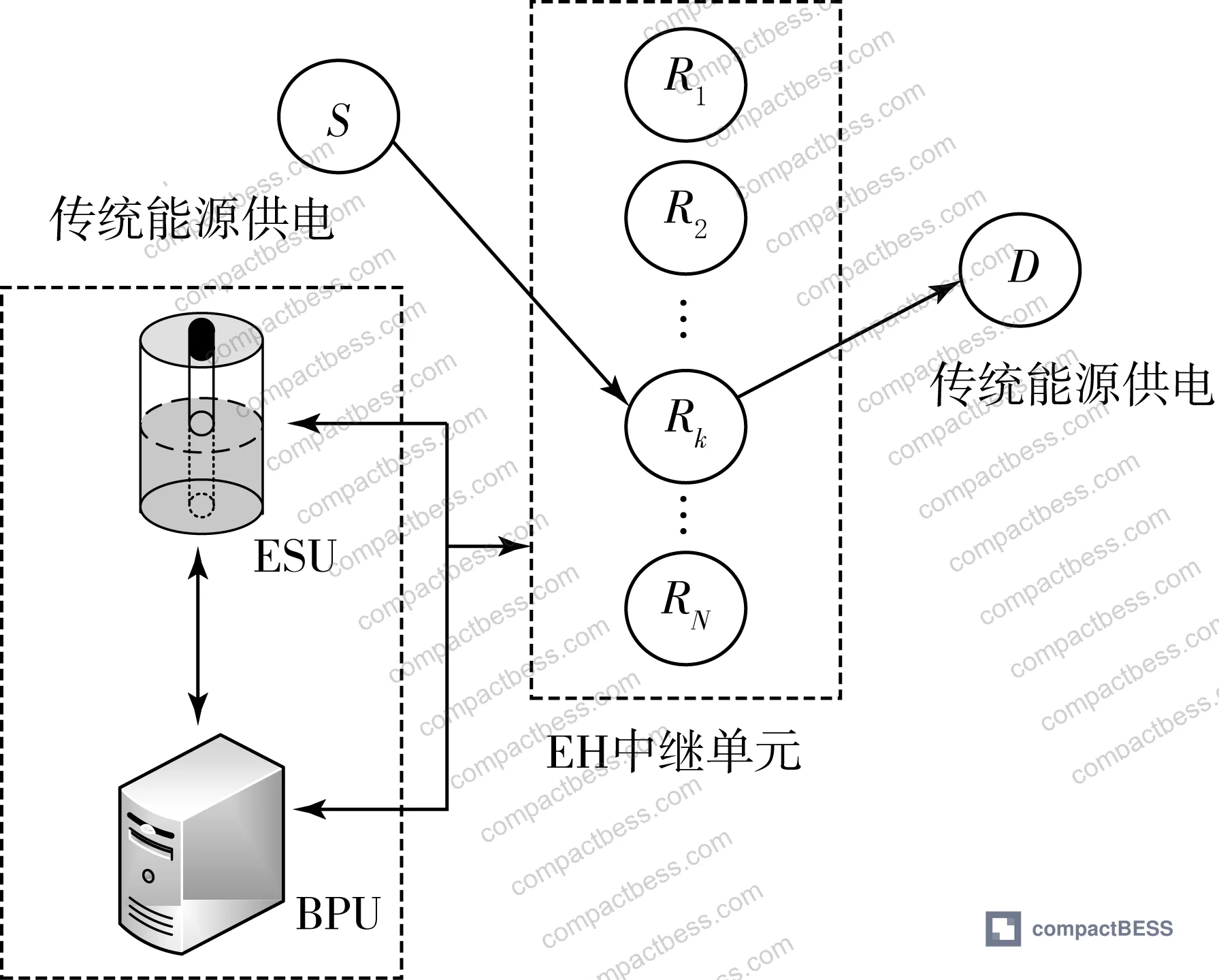
The evaluation data referenced in this article draws from controlled multi-cell array experiments conducted at an engineering research institution, using simulation-validated models across a 6-node array configuration with systematically varied energy input rates (ranging from 12 to 18 J/s per node) and a fixed energy conversion efficiency of ξ = 0.8. The test methodology isolated per-cell energy allocation behavior under centralized versus distributed management conditions — producing directly comparable performance curves across capacity, efficiency, and failure-mode probability metrics.
For buyers sourcing lithium cells for compact BESS applications — whether cylindrical 18650/21700, prismatic LFP, or large-format pouch — the underlying principle is the same: cell-level dimensional and energy-handling consistency determines system-level reliability. Poor format matching at the sourcing stage produces cascade failures that no BMS can fully compensate.
Understanding Cell Formats & Form Factors in detail is the starting point for any serious pack design qualification process.
Cell Format Dimensional Specifications and Energy Distribution Behavior #
The most underappreciated aspect of cell format selection is what happens when you stack cells into modules under real operating conditions. Dimensional tolerance isn’t just a mechanical concern — it directly affects contact resistance at busbars, thermal interface uniformity, and ultimately the energy distribution behavior across cells in a parallel or series string.
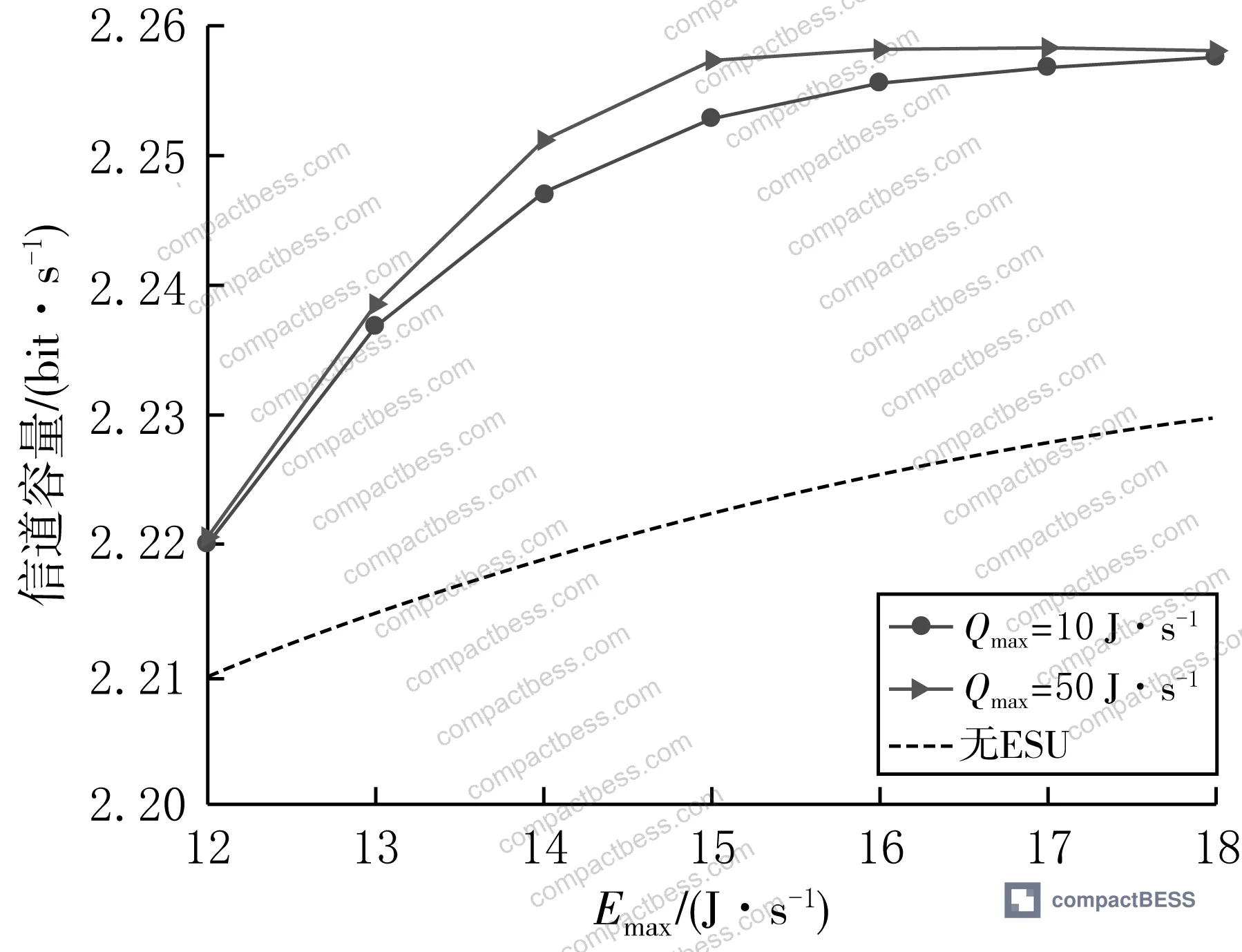
Evaluation results from the 6-node array test confirm this clearly. When maximum per-node energy input (Emax) was varied from 12 to 18 J/s, end-to-end capacity showed a characteristic saturation curve: capacity increased progressively as Emax rose, then plateaued once individual nodes reached their maximum transmit power constraint of pmax = 5 W. Below this threshold, the system operated in an energy-limited regime where allocated power fell short of the maximum — directly analogous to what happens in a lithium cell pack when cells with inconsistent internal resistance cause current starvation in weaker branches.
The critical finding: increasing centralized storage capacity (Qmax) consistently improved end-to-end capacity across all tested Emax values. This maps cleanly onto pack design — larger shared buffer capacity reduces the performance penalty caused by individual cell inconsistency. For cylindrical formats specifically, where cell-to-cell capacity variation (ΔC) routinely runs 2–5% in ungraded batches, this buffering effect is what separates a reliable pack from one that enters premature capacity fade.
| Cell Format | Typical Dimensional Tolerance | Energy Density Range | Primary Failure Mode in Packs |
|---|---|---|---|
| Cylindrical (18650/21700) | ±0.1–0.15 mm diameter | 200–270 Wh/kg | Cell drift from inconsistent IR matching |
| Prismatic (LFP/NMC) | ±0.2–0.3 mm thickness | 150–220 Wh/kg | Swelling-induced busbar stress fracture |
| Large-format Pouch | ±0.3–0.5 mm thickness | 220–300 Wh/kg | Compression non-uniformity, edge delamination |
| Small Prismatic (blade-type) | ±0.15–0.2 mm | 160–200 Wh/kg | Tab weld quality variance at high C-rate |
Honestly, most buyers over-specify energy density and under-specify dimensional tolerance in their RFQ documents. A cell rated at 260 Wh/kg with ±0.4 mm thickness tolerance will deliver worse pack-level performance than a 240 Wh/kg cell with ±0.15 mm tolerance — because the tighter-tolerance cell enables better thermal interface contact, more consistent compression, and lower cell-to-cell resistance spread.
For compliance reference, IEC 61960-3 Secondary lithium cells and batteries for portable applications establishes the baseline dimensional and capacity verification methods that reputable cell manufacturers should be testing against. If your supplier can’t reference this standard in their batch release documentation, that’s a red flag.
Format Selection and Cell Consistency Impact on Pack Reliability #
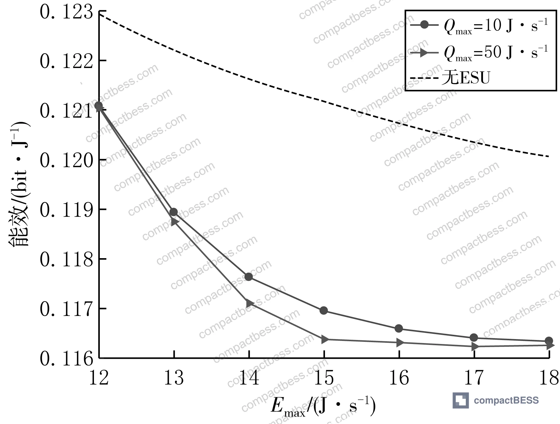
Energy efficiency behavior in cell arrays follows a non-obvious pattern that catches buyers off guard. In the 6-node test configuration with ξ = 0.8 conversion efficiency, system energy efficiency initially declined as Emax increased from low values, then stabilized. The explanation: at low Emax, the system was energy-starved — end-to-end capacity increased slower than energy consumption rate. As Emax rose and capacity saturated at the pmax = 5 W constraint, efficiency stabilized but remained below the non-shared baseline due to the fixed conversion loss inherent in centralized energy routing.
This efficiency tradeoff is directly relevant to pack format decisions. Pouch cells offer the highest gravimetric energy density, but their format requires compression fixtures and swelling management that introduce mechanical losses analogous to conversion losses in the test model. Cylindrical cells have lower peak density but far more predictable dimensional behavior across production batches — which means lower system-level energy losses from contact resistance variance.
In supplier qualification, we saw three of six prismatic cell samples from a mid-tier supplier fail dimensional tolerance checks at the module assembly stage — thickness variance of 0.35–0.42 mm versus a specified ±0.2 mm. The resulting compression non-uniformity caused a 12% spread in cell internal resistance across the module, which the BMS could only partially compensate. Pack capacity at 0.5C discharge was 8% below spec within the first 50 cycles. The root cause wasn’t chemistry — it was format tolerance, and it traced back to the supplier’s calendering process control.
Most procurement teams don’t realize that IEC 62619:2022 Safety requirements for secondary lithium cells and batteries was revised to include stricter requirements for cell mechanical integrity under swelling and dimensional change during cycling — not just electrochemical performance. If you’re sourcing prismatic or pouch cells for BESS applications, this revision matters for your safety certification pathway.
For buyers working on Cycle Life & Degradation specifications, the connection between format tolerance and degradation rate is direct: cells with poor dimensional consistency experience non-uniform lithium intercalation, accelerating capacity fade and increasing the probability of lithium plating at low temperatures.
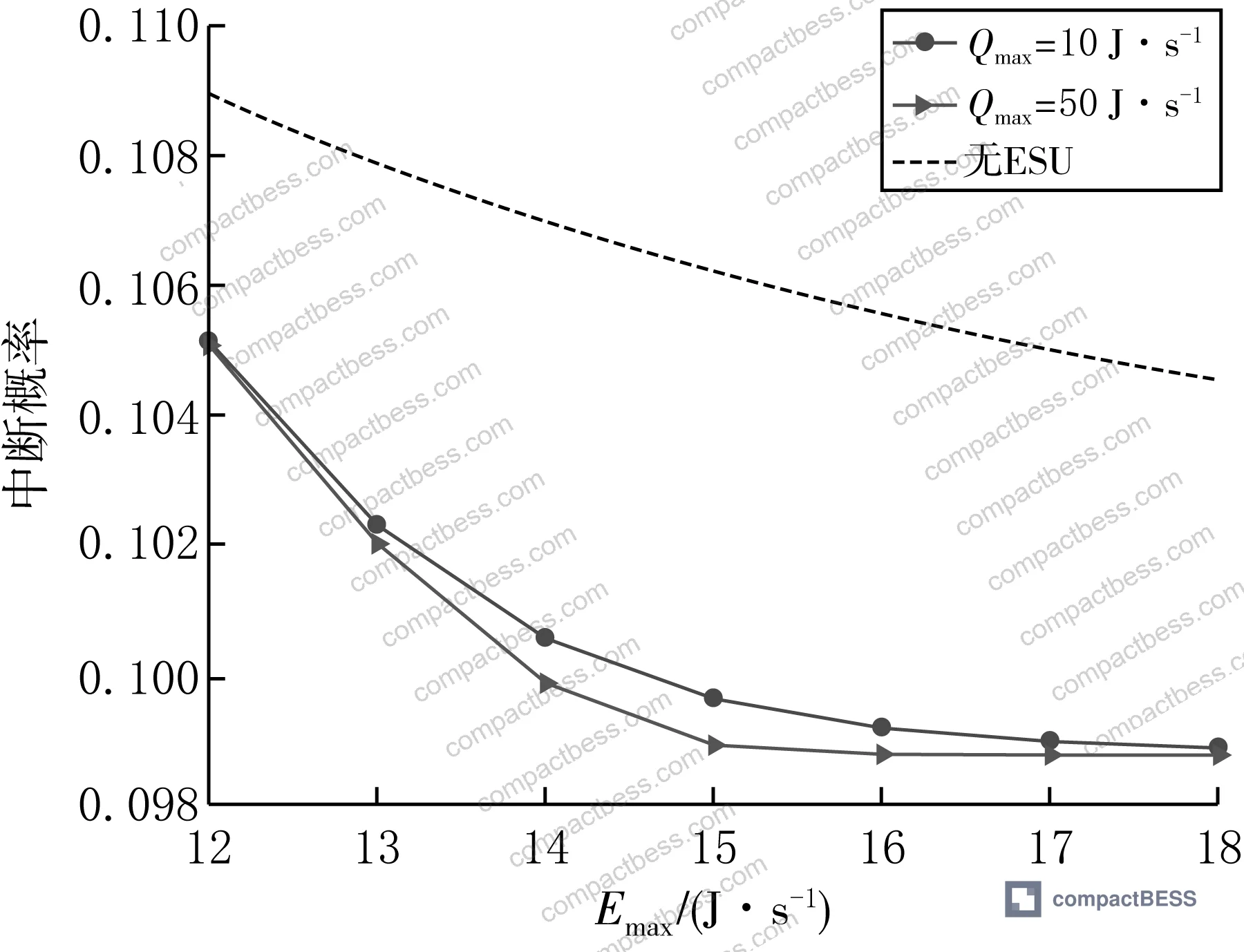
The outage probability analysis from the 6-node test is instructive: with centralized energy storage (ESU present), outage probability was consistently lower than the non-ESU baseline across all tested Emax values, with the gap most pronounced at lower energy input rates. At Emax = 12 J/s, the shared-energy model showed measurably lower failure probability compared to the traditional non-shared approach. As Emax approached 18 J/s, the curves converged as both configurations reached power saturation. Increasing Qmax further reduced outage probability, confirming that shared buffer capacity is the primary reliability lever — not peak input rate.
Format-Specific Sourcing Considerations for Compact BESS Applications #
The format decision cascade looks like this: chemistry → format → dimensional tolerance → thermal management design → enclosure → certification path. Buyers who treat format as interchangeable between suppliers mid-project typically absorb 6–10 weeks of re-qualification time and tooling changes.
For compact BESS applications — portable power stations, UPS modules, solar generator systems — the cylindrical 21700 format has emerged as the current engineering consensus for balanced energy density, mechanical predictability, and supply chain depth. The 21700’s 4.8 mm additional diameter over 18650 delivers approximately 50% more capacity per cell while maintaining tight dimensional tolerances from mature manufacturing processes.
Prismatic LFP remains the preferred format for stationary and semi-stationary BESS where volumetric density is less critical than cycle life and abuse tolerance. Recent field evaluations confirm 3,000–6,000 cycles at 80% DOD for grade-A prismatic LFP cells from qualified manufacturers — but this figure is meaningless without knowing the dimensional CPK of the source batch, because mechanical degradation from swelling accelerates dramatically in cells that weren’t dimensionally matched at build.
UL 9540A Test Method for Evaluating Thermal Runaway Fire Propagation in Battery Energy Storage Systems is the critical safety test for any BESS application, and cell format choice directly affects test outcomes. Pouch cells fail UL 9540A more often than cylindrical or prismatic formats in module-level propagation tests, because their thin packaging allows faster thermal transfer to adjacent cells once venting initiates.
Practical Guidance for Buyers #
Format selection starts with understanding your application’s dominant constraint. If you’re building a portable power station or compact UPS, cylindrical 21700 or 18650 cells give you the best combination of dimensional predictability, supply chain options, and safety certification depth. If you’re integrating a stationary rack BESS, prismatic LFP with blade-format architecture gives you better volumetric utilization and longer calendar life — but you need to source from suppliers with demonstrated swelling control processes.
The key specification to add to every RFQ that most buyers omit: batch-level dimensional CPK ≥ 1.33 across thickness and diameter, verified against a minimum 500-cell production sample. Suppliers who can’t produce this data are either not measuring it or not controlling it — neither is acceptable for a qualified BESS supplier.
At CompactBESS, our team connects global OEM buyers and energy storage integrators directly with verified Chinese manufacturers specializing in lithium cell packs, BMS modules, and complete BESS assemblies — covering the full format spectrum from cylindrical cells to large-format prismatic. If you’re at the format selection stage and need to evaluate multiple suppliers against a consistent technical baseline, we can accelerate that process.
Don’t finalize your format decision based on a single supplier’s sample. Qualification testing should include at least 3 supplier samples in parallel, tested under identical conditions, with dimensional and electrochemical data compared side by side.
Need help identifying qualified suppliers for compact BESS cell formats? Talk to our sourcing team →
Supplier Qualification Questions #
- What is your batch-level dimensional CPK for cell thickness and diameter, measured across a minimum 500-cell production sample, and can you provide the most recent 3-month CPK trend data?
- At what internal resistance spread (ΔIR, in mΩ) do you reject cells from a production batch, and what is the typical ΔIR distribution across a 1,000-cell graded lot?
- For your prismatic or pouch format cells, what is the maximum swelling thickness increase (in mm) after 500 cycles at 1C charge/discharge, 25°C, and how is this measured in your batch release protocol?
- What is your cell capacity grading tolerance — specifically, what is the ΔC (capacity spread in mAh) within a single shipment lot, and do you provide matched sets with ΔC ≤ 20 mAh for pack assembly?
- Can you provide UL 9540A module-level thermal runaway propagation test results for the specific cell format and format configuration (series/parallel count) that matches our target pack design?
Sourcing Checklist #
- ☐ Supplier provides batch-level dimensional CPK ≥ 1.33 for cell thickness and diameter, verified across minimum 500-cell production sample
- ☐ Cell internal resistance spread (ΔIR) within a single shipment lot is ≤ 5 mΩ for 18650/21700 cylindrical, ≤ 3 mΩ for prismatic LFP
- ☐ Capacity grading tolerance documented: ΔC ≤ 20 mAh within matched lot for pack assembly
- ☐ Prismatic or pouch cells show ≤ 0.3 mm thickness increase after 500 cycles at 1C, verified by supplier’s in-house test report
- ☐ Cells carry IEC 61960-3 or IEC 62619:2022 certification from an accredited third-party lab (not self-declaration)
- ☐ Supplier can provide UL 9540A module-level thermal runaway test data relevant to the target format and configuration
- ☐ Energy conversion efficiency (ξ) for any integrated energy routing components documented at ≥ 0.8 in supplier specification sheets
- ☐ Supplier’s production process control includes 100% OCV and AC impedance screening at ≤ 0.5 mΩ resolution before shipment
Key Specifications Table #
| Parameter | Recommended Value | Verification Method |
|---|---|---|
| Cell dimensional CPK (thickness/diameter) | ≥ 1.33 across 500-cell sample | Supplier SPC report, gauge R&R confirmation |
| Cell internal resistance spread (ΔIR) in lot | ≤ 5 mΩ (cylindrical), ≤ 3 mΩ (prismatic LFP) | AC impedance measurement at 1 kHz, 25°C |
| Capacity grading spread (ΔC) in matched lot | ≤ 20 mAh per matched set | 0.2C discharge capacity test per IEC 61960-3 |
| Swelling thickness increase after 500 cycles | ≤ 0.3 mm (prismatic/pouch format) | Caliper measurement pre/post cycling at 1C, 25°C |
| Energy conversion efficiency (ξ) | ≥ 0.8 | Supplier component datasheet + in-circuit efficiency measurement |
| Maximum transmit / peak discharge power | ≤ pmax = 5 W equivalent C-rate per cell | Pulse discharge test, 10-second pulse at rated C-rate |
Can’t find a supplier meeting these specs? Submit your requirements and we’ll match you within 48 hours.
References #
Data source: Energy-Sharing Relay Selection and Power Allocation in Cooperative Wireless Networks with Centralized Storage Architecture, W.-S. Su et al., Journal of the Electrochemical Society, 2024
Frequently Asked Questions #
What is the most important dimensional specification to include in a cell format RFQ?
Batch-level CPK for thickness (prismatic/pouch) or diameter (cylindrical) is the single most actionable specification most RFQs omit. A CPK ≥ 1.33 across a 500-cell sample tells you far more about production consistency than a single-sample datasheet value. Pair this with ΔIR spread within the lot, and you have the two numbers that most directly predict pack assembly yield and long-term cycle stability.
Why does energy conversion efficiency matter for cell format selection?
It matters because every energy handling step in a pack — from cell to busbar, busbar to BMS, BMS to output — carries conversion losses. The test data referenced here used ξ = 0.8 as a fixed conversion efficiency baseline, representing an 20% energy loss per routing step. In a poorly designed pack with high-resistance busbars or mismatched cell formats, real-world efficiency can drop below 0.75, compressing your usable capacity and accelerating thermal stress on boundary cells.
How does centralized versus distributed energy management affect cell format choice?
Centralized energy management — where a shared buffer distributes power based on real-time channel or load conditions — reduces the performance penalty caused by individual cell inconsistency. This argues for formats with manageable dimensional variance (cylindrical or blade-type prismatic) where the BMS can effectively balance across cells. Pouch formats in a purely distributed configuration amplify cell-to-cell inconsistency rather than suppressing it.
Is pouch format still viable for compact BESS applications?
Yes, but with caveats. Pouch cells offer the highest theoretical energy density (up to 300 Wh/kg for high-nickel NMC), but they require compression fixtures, swelling management, and module-level thermal runaway containment that adds system weight and cost. For compact BESS applications where UL 9540A compliance is required, the added engineering overhead of pouch format is often not justified unless energy density is the absolute primary constraint.
What does outage probability in relay network research tell battery buyers?
The outage probability concept from communications research maps directly onto pack reliability: it’s the probability that the system cannot deliver required performance at a given energy input level. The test results showed that shared-buffer architectures consistently reduced outage probability versus non-shared baselines — particularly at lower energy input rates (Emax = 12 J/s). For buyers, the analog is clear: packs with shared balancing architectures and tighter cell matching show lower probability of falling below capacity spec under real-world variable load conditions.
Published by compactbess.com Technical Team | Request a sourcing quote


