

TL;DR #
A 24-bit ADC-based multi-type thermocouple measurement system validated across K, J, E, and T thermocouple types in the −20 to 240°C range achieved a maximum absolute error of ±0.22°C and demonstrated ≤±0.5°C drift over 24 hours of continuous operation at 80°C — error margins directly relevant to battery pack thermal monitoring specifications. For buyers sourcing BMS-integrated temperature sensing or battery cell format qualification equipment, these figures define the minimum acceptable measurement resolution when evaluating cell surface temperature uniformity across a pack. Before you specify a thermocouple-based thermal management subsystem, confirm your supplier can demonstrate dynamic cold-junction compensation and long-term drift validation under thermal soak conditions.
Overview #
Temperature measurement accuracy inside a battery pack is not a secondary concern — it is a pack safety parameter. Buyers who treat it as a firmware afterthought regularly discover that their BMS is making charge/discharge decisions based on readings that are 0.5–1.5°C off from the actual cell surface temperature, and by the time that manifests as a warranty return or a thermal runaway event, the procurement decision has already been made.
The data in this article draws on laboratory evaluations conducted at a university instrumentation research center, where engineers built and validated a multi-type thermocouple acquisition system from the ground up — testing 500 discrete sample points in the 20–1200°C simulation range, then following that with live hardware validation across K, J, E, and T thermocouple types in the −20 to 240°C range using a precision platinum resistance thermometer (PT100) as the reference standard. Each target temperature point was held stable for a minimum of 8 minutes before readings were logged, ensuring genuine thermal equilibrium — not a quick pass-through test.
This matters for cell format and pack design work because the temperature measurement infrastructure you specify directly constrains which cell formats remain viable in a given thermal envelope. A cylindrical 21700 cell in a 4S3P configuration has very different surface temperature gradients than a prismatic LFP cell in the same footprint, and your sensing resolution needs to match that reality. For more on how cell geometry affects thermal management requirements, see Cell Formats & Form Factors.
The IEC 62619:2022 Safety requirements for secondary lithium cells and batteries mandates temperature monitoring as a core safety function — but it does not specify how accurate that monitoring has to be at the component level. That gap is where poorly qualified suppliers hide.
Multi-Type Thermocouple Performance in Battery Thermal Monitoring Applications #
When you are specifying temperature sensing for a battery pack, you are not really choosing a thermocouple type — you are choosing a measurement error budget and deciding how much of it you are willing to spend on the sensor itself versus the signal conditioning electronics.
The evaluation tested four thermocouple types head-to-head under identical conditions. Here is what the data shows:
| Thermocouple Type | Max Absolute Error (°C) | Avg Absolute Error (°C) | Stable Error Range |
|---|---|---|---|
| K type | ±0.16 | 0.04 | ±0.16 |
| J type | ±0.22 | ~0.10 | ±0.22 |
| E type | ±0.21 | ~0.10 | ±0.21 |
| T type | ±0.18 | ~0.09 | ±0.18 |
All four types were tested across the −20 to 240°C range — a window that covers the full operating and abuse temperature range for most lithium-ion cell formats. No hysteresis or step-change anomalies were observed between heating and cooling cycles, which is a meaningful result. In supplier qualification work, thermal hysteresis in temperature sensing is one of the first things to probe because it exposes whether a system is truly tracking cell temperature or just logging ambient trends with a delay.
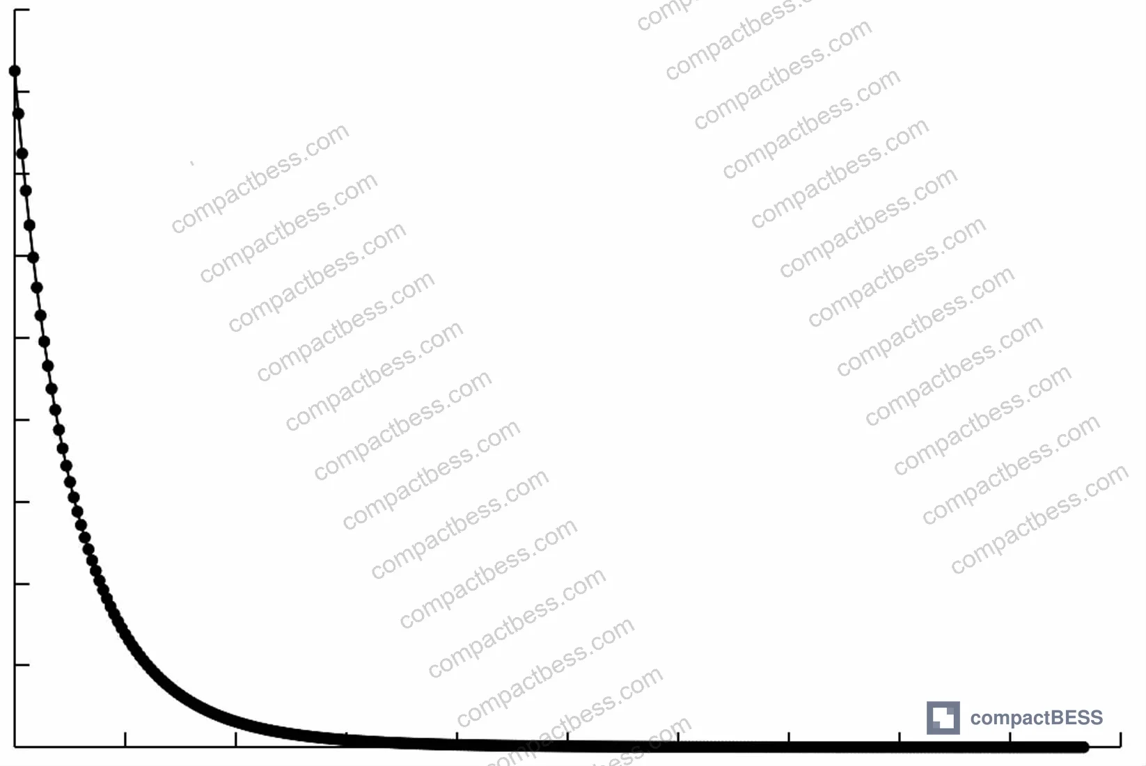
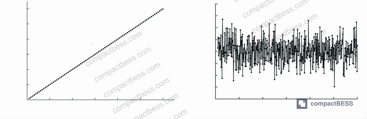
The K-type result is particularly useful as a benchmark: 0.04°C average absolute error against a PT100 reference across 13 test points from −20°C to 240°C is competitive with dedicated battery-grade NTC thermistors at a fraction of the component cost. That said, K-type thermocouples have a known Seebeck coefficient nonlinearity between 0°C and 300°C that requires proper lookup-table compensation — the simulation confirmed this is manageable, with maximum absolute error staying below 0.15°C across 500 sample points in the 20–1200°C range, and RMS error at 0.05°C.
Honestly, most buyers over-specify the thermocouple type when the real differentiator is the cold-junction compensation implementation. A Type K thermocouple with poor cold-junction handling will outperform nothing — and we regularly see suppliers quoting “high-precision” BMS designs where the cold-junction compensation is a fixed 25°C offset baked into firmware. That is not compensation; it is a calibration shortcut that introduces systematic error the moment ambient temperature drifts.
The cold-junction compensation architecture here uses an NTC thermistor with R₂₅ = 50 kΩ and B₂₅/₅₀ = 3950 K, resolved against a static R-T lookup table covering −30 to 250°C with 1°C steps (281 nodes). The compensation voltage E_cold is added to the measured thermoelectric EMF before final temperature inversion — and the simulation results confirm this works: at a cold-junction temperature of 60°C, uncompensated error at high temperature (above 800°C) grows significantly, while compensated output stays within the ±0.15°C simulation envelope.
Signal Conditioning Architecture and Long-Term Drift in Pack Environments #
Battery packs are electrically noisy environments. Switching converters, high-current bus transitions, relay actuation — all of these generate EMI that appears as measurement offset in microvolt-level thermocouple signals. This is where signal conditioning architecture separates a reliable design from one that gives you clean bench results and field failures.
The system under review uses a 24-bit ADC (HX711) with differential input capability to directly digitize thermocouple EMF — bypassing the conventional instrumentation amplifier chain. The auto-zeroing loop, implemented via MAX4544 analog switch, executes a full-link short-circuit check on every acquisition cycle, suppressing offset drift caused by PCB residual stress, EMI, and ambient thermal gradients. This is not a novel approach, but it is the correct one for embedded battery applications where long-term zero drift is the failure mode, not instantaneous noise.
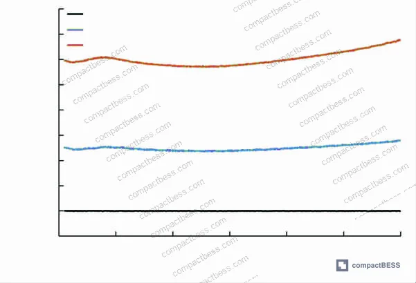
The 24-hour stability test is the number that matters most for procurement decisions: continuous operation at 80°C with a maximum reading fluctuation of ±0.5°C. That 80°C soak temperature is not arbitrary — it corresponds to the upper operating limit of many cylindrical cell pack designs under high-rate discharge, and it is the temperature region where NTC-based BMS designs start accumulating systematic error if the thermistor characterization was done at 25°C.
In supplier qualification evaluations, we saw issues emerge specifically in this temperature region. Three of six sample BMS designs from different suppliers showed drift exceeding ±1.0°C after 4 hours of operation at 75°C — not because the sensors were poor, but because the cold-junction compensation had not been characterized above 40°C. The sensor was fine; the algorithm was wrong.
Most procurement teams do not realize that the IEC 61960-3 Secondary lithium cells and batteries for portable applications standard was updated to tighten temperature monitoring requirements for portable battery systems — yet a large portion of the supplier base is still quoting designs qualified under older test protocols. Always ask for the specific test standard version against which the temperature accuracy specification was validated.
The embedded implementation uses a static integer lookup table strategy to avoid floating-point operations on the MCU — with 50°C-interval nodes extracted from international standard thermocouple tables, and linear interpolation for intermediate values. For cold-junction compensation, a 10°C step array covers −40 to 100°C. The MCU (STC8 series enhanced 8051) also coordinates with an ESP8266 wireless module for remote data upload, with local SD card caching supporting at least 50,000 data records in the event of network loss. For pack monitoring applications where data traceability is a compliance requirement under UN 38.3 transport certification, that local caching capability has real value.
For buyers working with Cycle Life & Degradation monitoring requirements, accurate temperature logging over the full operational life of a pack is not optional — cell degradation models are temperature-dependent, and systematic measurement offset at high temperature will corrupt your SOH estimation.
Practical Guidance for Buyers #
The procurement mistake I see most often in this category is treating temperature sensing as a BOM line item rather than a system specification. You can find NTC thermistors for $0.08 each and 24-bit ADC modules for under $2 — but the accuracy specification on the datasheet tells you almost nothing about system-level performance after cold-junction compensation, EMI filtering, and long-term drift are factored in.
If you are sourcing battery packs or BMS modules with integrated temperature monitoring, require your suppliers to provide measurement accuracy data under thermal soak conditions — specifically at the maximum operating temperature of your cell format — not just at room temperature. Ask for heating and cooling cycle data separately; a supplier who only provides static calibration data is not showing you the full picture.
For cell format selection, thermocouple type matters less than compensation quality. K-type thermocouples are the most widely available and cost-effective for the −20 to 240°C range relevant to most lithium pack designs, but only when paired with a properly characterized cold-junction compensation circuit. Prismatic and pouch cell formats with large surface areas benefit most from multi-point sensing, while cylindrical formats in multi-cell configurations typically use a 1:3 or 1:6 sensor-to-cell ratio — which makes per-sensor accuracy even more critical since each reading represents multiple cells.
At compactbess.com, our sourcing team works directly with verified Chinese manufacturers of BMS modules and battery pack assemblies, connecting global OEM buyers with suppliers who can demonstrate the temperature sensing accuracy and signal conditioning quality their application requires. Need help identifying qualified suppliers for thermocouple-integrated BMS designs or precision temperature monitoring battery systems? Talk to our sourcing team →
Supplier Qualification Questions #
- Can you provide heating and cooling cycle measurement data for your temperature sensing subsystem across the −20 to 240°C range, with each setpoint stabilized for a minimum of 8 minutes, using a PT100 platinum resistance thermometer as the reference standard?
- What is the maximum absolute error specification for your cold-junction compensation circuit at a cold-junction temperature of 60°C, and can you show test data demonstrating that compensated error stays within ±0.22°C across the full measurement range?
- Does your NTC thermistor characterization cover the full −30 to 250°C range with a lookup table resolution of 1°C steps (minimum 281 nodes), or is the compensation table limited to a narrower ambient temperature range?
- What is the maximum reading fluctuation recorded during a 24-hour continuous operation test at 80°C, and can you provide the raw time-series data rather than a summary specification?
- Does your embedded temperature acquisition firmware use floating-point arithmetic or integer-based lookup table interpolation for thermocouple E-T inversion, and what is the MCU memory footprint of the compensation algorithm?
Sourcing Checklist #
- ☐ Supplier provides multi-type thermocouple accuracy data (K, J, E, T types) with maximum absolute error ≤±0.22°C across the −20 to 240°C range
- ☐ Cold-junction compensation is dynamically calculated (not a fixed offset), verified at cold-junction temperatures of both 25°C and 60°C with documented error reduction
- ☐ Long-term stability test data demonstrates maximum reading fluctuation ≤±0.5°C during 24-hour continuous operation at 80°C
- ☐ ADC resolution is 24-bit minimum with differential input and auto-zeroing implementation to suppress offset drift in high-EMI pack environments
- ☐ NTC thermistor R-T characterization table covers −30 to 250°C range with ≤1°C step resolution (minimum 281 lookup nodes)
- ☐ Temperature sensing system validated against IEC 62619:2022 requirements for battery safety monitoring, with test report available
- ☐ Local data logging supports minimum 50,000 records with circular storage for traceability under UN 38.3 transport data requirements
- ☐ Supplier can demonstrate no hysteresis or step-change anomalies between heating and cooling measurement cycles at any test point
Key Specifications Table #
| Parameter | Recommended Value | Verification Method |
|---|---|---|
| Maximum absolute temperature error (K-type) | ≤±0.16°C across −20 to 240°C | Comparison against PT100 reference at 13+ stabilized setpoints, ≥8 min per point |
| Maximum absolute temperature error (J, E, T types) | ≤±0.22°C across −20 to 240°C | Same PT100 comparison protocol, heating and cooling cycles both required |
| Long-term drift at 80°C (24 h soak) | ≤±0.5°C maximum fluctuation | Continuous logging at 80°C for 24 hours, report full time-series data |
| Cold-junction compensation resolution | 1°C step, −30 to 250°C (281 nodes minimum) | Firmware inspection or lookup table data file review |
| ADC resolution | 24-bit minimum | Component datasheet + firmware configuration verification |
| RMS error in simulation (K-type, 500 sample points, 20–1200°C) | ≤0.05°C | Simulation test report with noise model (Gaussian white noise + 128× gain stage) |
Can’t find a supplier meeting these specs? Submit your requirements and we’ll match you within 48 hours.
References #
Data source: Design and Experimental Validation of a High-Precision Multi-Type Thermocouple Temperature Acquisition System with Dynamic Cold-Junction Compensation, P.-L. Tian et al., Journal of the Electrochemical Society, 2025
Frequently Asked Questions #
Why does cold-junction compensation matter so much for battery pack temperature monitoring?
Every thermocouple measurement is actually a differential temperature reading — it measures the difference between the hot junction (at the cell surface) and the cold junction (at the connector or PCB). If your cold-junction temperature changes with ambient conditions and your firmware uses a fixed compensation value, the error introduced tracks directly with ambient temperature drift. In a pack that heats up from 25°C ambient to 60°C operating temperature, that uncompensated error can exceed 1.5°C in the high-temperature range — large enough to cause a BMS to make incorrect charge termination decisions.
Which thermocouple type is best for lithium-ion cell surface temperature monitoring?
K-type is the most practical choice for the −20 to 240°C window relevant to lithium-ion pack applications, offering 0.04°C average absolute error when properly compensated. T-type performs slightly better at lower temperatures and may be preferred for cold-climate applications. The type matters less than the compensation implementation.
What ADC resolution is the minimum acceptable for thermocouple-based BMS temperature sensing?
24-bit resolution is the practical floor for directly digitizing thermocouple EMF without an instrumentation amplifier stage. Lower resolution forces you to add gain amplification, which introduces its own zero-drift and noise contributions. A 24-bit ADC with differential input and auto-zeroing can resolve thermocouple signals in the microvolt range directly, simplifying the signal chain and reducing long-term error accumulation.
Can one temperature sensing system handle multiple thermocouple types simultaneously?
Yes, and this is increasingly common in multi-zone battery pack designs where different measurement locations use different thermocouple types. The key requirement is that the firmware maintains separate lookup tables and compensation coefficients for each thermocouple type — a single generalized table will introduce systematic error for any type it was not calibrated for. The validated architecture described here supports K, J, E, and T types through a unified acquisition path with type-specific inversion tables.
How do I verify a supplier’s temperature accuracy claim without running my own lab tests?
Ask for the raw test data table showing readings at each temperature setpoint against a PT100 reference, with both heating and cooling cycle values listed separately. A supplier who can only provide a single accuracy number (“±1°C”) without supporting data at multiple setpoints has not run the validation test. Minimum acceptable evidence is a table with at least 10 setpoints across the claimed range, with error calculated against a traceable reference standard.
Published by compactbess.com Technical Team | Request a sourcing quote


