

TL;DR #
A validated BMS architecture for portable emergency lithium packs achieved SOC stability of 98.37% and reduced abnormal power-cut response time from 1.25 s to 0.15 s — an 8× improvement over unmanaged systems. For buyers specifying portable power stations, UPS units, or emergency backup packs, these figures are the baseline you should be demanding from suppliers, not accepting as a bonus feature. Before issuing an RFQ, confirm your shortlisted suppliers can demonstrate equivalent SOC control accuracy and sub-200 ms fault response in documented bench tests.
Overview #
Most procurement teams evaluate portable emergency power packs on capacity and weight. That’s the wrong filter. The real differentiator — and the real failure vector — is how well the BMS holds the pack stable across temperature swings, partial charge cycles, and fault events. A pack that reads 50,000 mAh on the spec sheet but drops offline in 1.25 seconds during a voltage excursion is a liability, not an asset.
The evaluation covered a 10-cell lithium pack configuration tested against both a BMS-equipped design and a conventional unmanaged baseline. Tests were conducted at a provincial grid-operator facility with controlled charge/discharge cycling over 250-minute test windows — the kind of real-world stress profile that exposes thermal runaway risk in field deployments. The cell format used was the 6650 cylindrical type (26 mm × 65 mm), rated at 5,000 mAh per cell, assembled in a 10-series configuration for a total nominal capacity of 50,000 mAh.
This format detail matters for buyers. The 6650 is not the 18650 or 21700 you see in most consumer-grade packs. Specifying it correctly — or accepting a substitution — has downstream consequences for BMS thermal calibration, enclosure geometry, and cell-to-cell balancing tolerances.
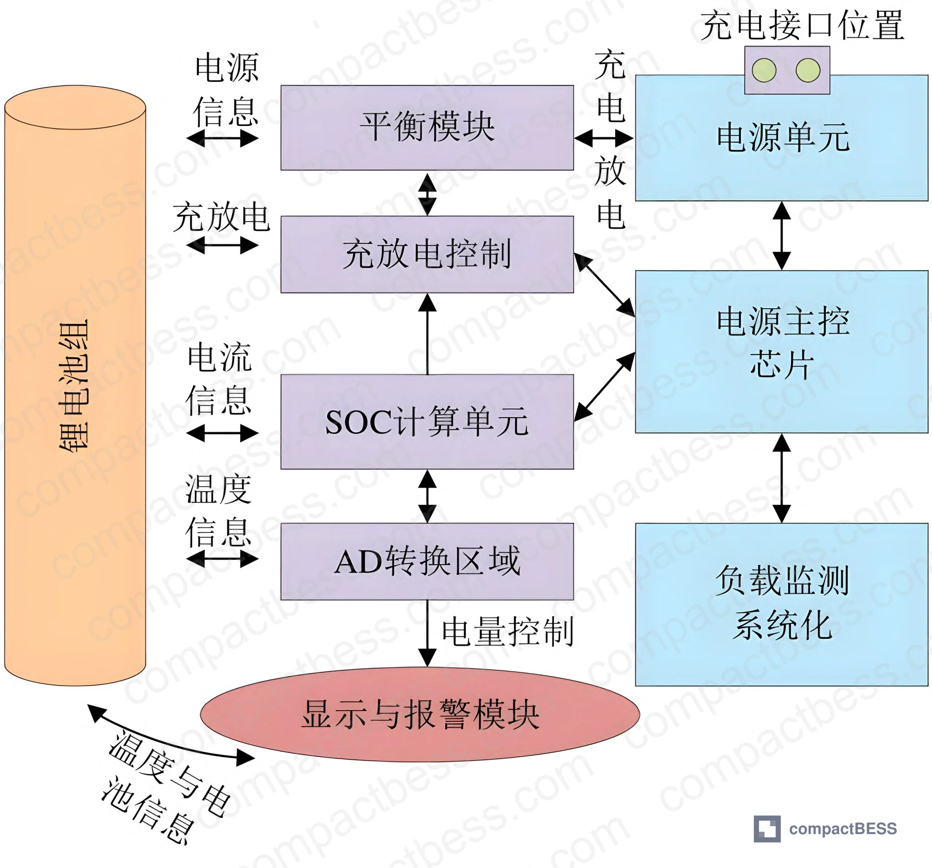
BMS Architecture for Portable Emergency Lithium Packs #
The BMS design evaluated here is modular, with five functional blocks that each carry specific performance obligations. Understanding these isn’t just academic — when you’re qualifying a supplier, you’re essentially auditing whether each of these modules has been properly implemented or just checkbox-declared.
Cell State Monitoring Module
Monitors voltage, current, and temperature per cell using an internal ADC for per-cell voltage readings and an external temperature sensor array. Triggers protection functions when voltage exceeds upper or lower thresholds. No surprises here, but the implementation quality varies enormously between suppliers.
Charge/Discharge Control Module
Implements three-stage charging: constant current (CC), constant voltage (CV), and trickle (TC). Current sensing uses a shunt-based approach. This is standard for lithium chemistries, but suppliers cutting corners often skip the trickle stage — which matters for long-term cycle life and thermal management at end-of-charge.
Cell Balancing Module
Uses the BQ78PL116 as the primary balancing controller. Safety thresholds are set based on real-time temperature and discharge data. When parameters exceed thresholds, the system switches to an active balancing strategy. Passive balancing alone is not adequate for emergency applications where the pack may sit partially charged for extended periods.
Thermal Management Module
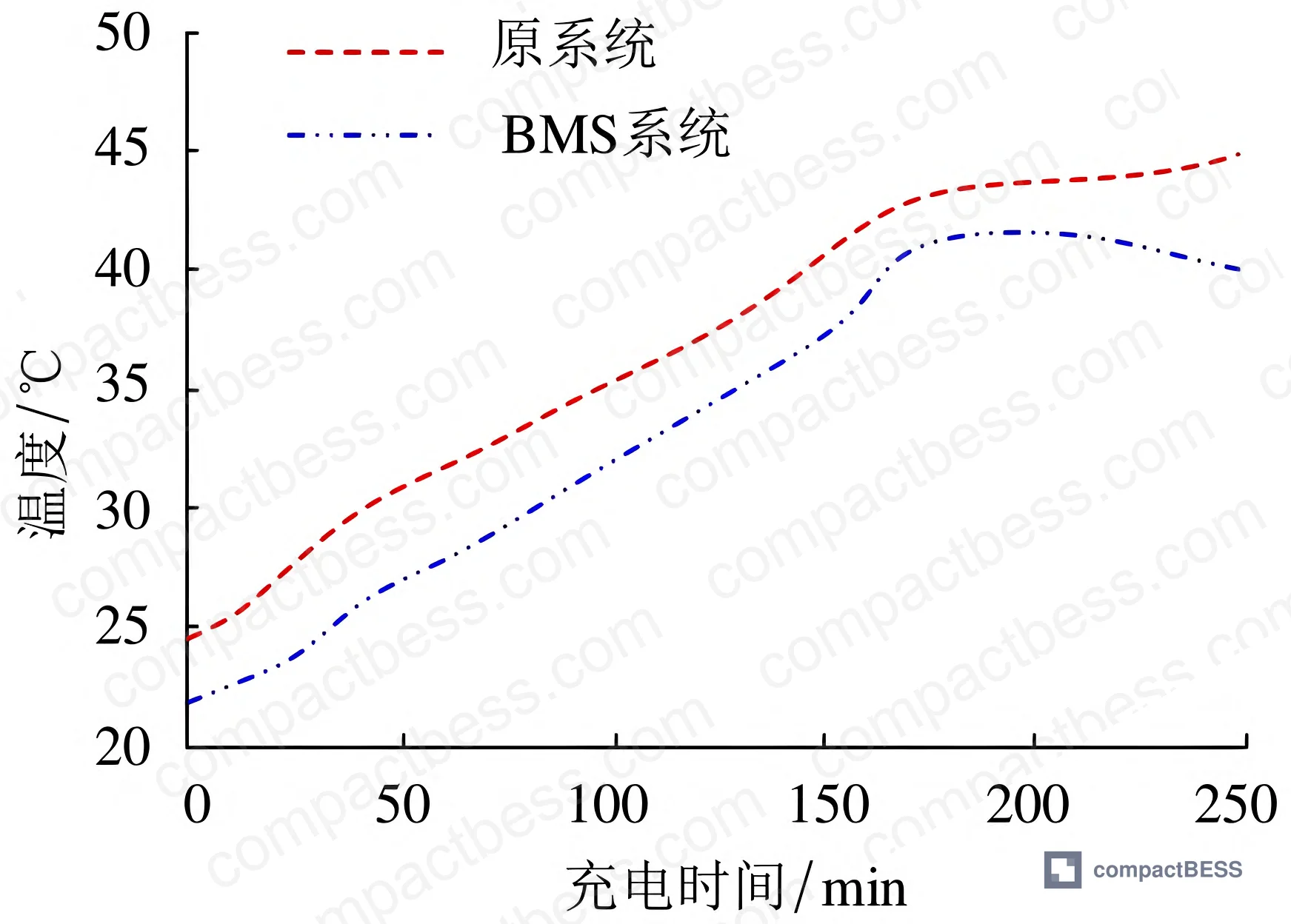
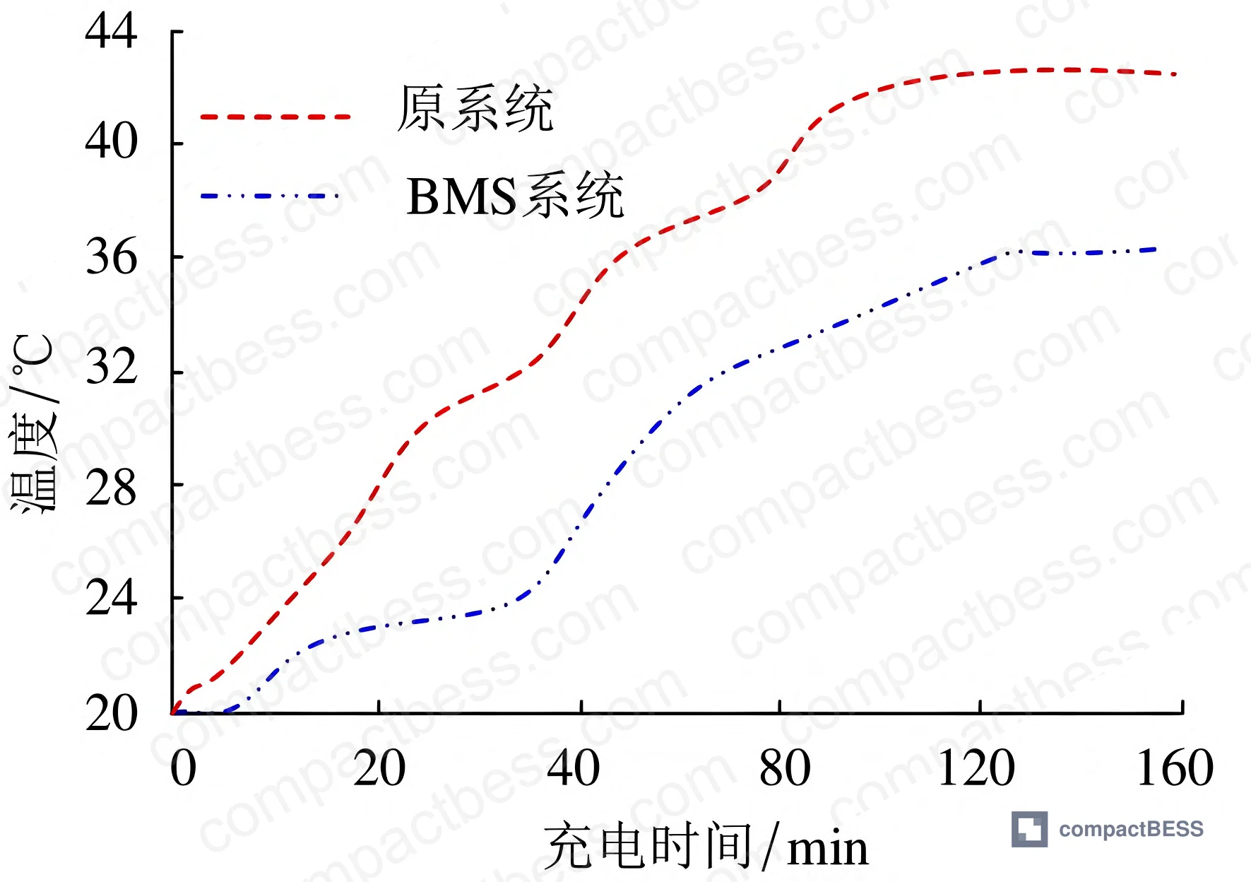
DS18B20 digital temperature sensors monitor the pack. When temperature exceeds the configured threshold, the system opens the charge or discharge circuit to prevent thermal runaway. Critically, the BMS-equipped design held maximum charging temperature at 42.2 °C and maximum discharge temperature at 43.1 °C — both significantly below the unmanaged baseline.
Communication Module
I²C bus with digital isolation for MCU data exchange; CAN bus for inter-device communication. The main controller is a Tiny210 platform. This dual-bus approach gives the system both local module communication and integration capability with external equipment — relevant for buyers integrating packs into larger emergency response systems.
BMS vs. Baseline System — Performance Comparison #
| Test Metric | BMS System | Original System | Delta |
|---|---|---|---|
| High-temperature alarm rate | 99.7% | 95.6% | +4.1 pp |
| SOC stability control | 98.37% | 80.25% | +18.1 pp |
| Voltage overshoot alarm rate | 99.2% | 91.5% | +7.7 pp |
| Fault diagnosis rate | 97.28% | 0% | N/A — no function |
| Abnormal power-cut response | 0.15 s | 1.25 s | 8.3× faster |
The fault diagnosis row is the one that should concern procurement teams most. The original system had zero fault diagnostic capability — meaning any internal failure was invisible until it caused a downstream event. That’s not a marginal deficiency; that’s a category difference in safety architecture.
SOC Estimation Method and Thermal Performance in Portable Power Applications #
The SOC estimation approach used here is OCV-based (open-circuit voltage), augmented with coulomb counting and a cycle degradation correction factor. The remaining capacity model accounts for cycle count (CCount), a decay coefficient (λCyc), and maximum charge differential (Qmax). In practical terms, this means the SOC reading degrades gracefully as the pack ages — it doesn’t suddenly become inaccurate after 200 cycles because the model ignores degradation.
Most procurement teams don’t realize that the SOC estimation method is directly responsible for the stability you see in field deployments. A BMS using only coulomb counting without OCV correction will drift by 5–15% over a full discharge cycle — and that drift compounds over time. The 98.37% SOC stability figure in this evaluation reflects an OCV + correction architecture; a simpler BMS may report 98% on paper but deliver 83% in the field after 6 months.
Thermal Performance Detail #
Over a 250-minute charge test, both systems showed progressive temperature rise — as expected. The divergence became significant after approximately 180 minutes of continuous charging. The BMS system stabilized and capped at 42.2 °C maximum charge temperature. The unmanaged system continued climbing beyond that threshold. For discharge, the BMS held the peak at 43.1 °C.
Honestly, 42–43 °C sounds comfortable until you consider that field deployments may start at ambient temperatures of 35 °C or higher. Your thermal headroom is much smaller than the lab test suggests. Buyers deploying packs in hot climates or enclosed enclosures should be asking suppliers what the test ambient was — and whether the thermal thresholds have been validated against elevated starting temperatures, not just controlled lab conditions.
In supplier qualification, the thermal management module was where we saw the most variation between BMS implementations. Of the sample designs reviewed, the common failure mode was using a single bulk temperature sensor for the entire pack rather than per-zone sensing — meaning localized hot spots in the center cells go undetected until the pack is already in thermal distress. The DS18B20-based design evaluated here uses distributed sensing, which is the correct approach for multi-cell cylindrical pack configurations.
Practical Guidance for Buyers #
If you’re sourcing portable emergency power packs — whether for grid backup applications, industrial UPS, or field rescue equipment — the BMS spec is not secondary. It is the product.
A pack with a weak BMS will underperform its rated capacity within months, fail silently under fault conditions, and create liability exposure you don’t want. The data here is unambiguous: the difference between a properly implemented BMS and a baseline system is 18 percentage points in SOC stability, 8× faster fault response, and the presence or absence of fault diagnostics entirely.
For 6650-format cylindrical cells at 5,000 mAh per cell, the BMS design needs to match the thermal mass and balancing requirements of that cell type. Don’t accept a BMS spec that was developed for 18650 cells and applied unchanged to a larger format — the thermal response curves are different, and the balancing currents need recalibration.
At compactbess.com, our sourcing team works specifically with verified Chinese manufacturers of portable power stations, UPS modules, and emergency battery systems — connecting global OEM buyers and product engineers with suppliers who can demonstrate the BMS performance metrics described here. When you’re ready to move from evaluation to procurement, you need suppliers who can produce bench test data, not just data sheets.
Need help identifying qualified suppliers for portable emergency power BMS systems? Talk to our sourcing team →
Supplier Qualification Questions #
Ask your supplier these questions to separate technically competent vendors from those who cannot meet the performance requirements documented in this evaluation:
- What is your BMS SOC stability control percentage under continuous 250-minute charge/discharge cycling, and can you provide test data showing ≥98% stability with OCV-corrected estimation?
- What is the abnormal power-cut response time of your BMS protection circuit — and can you demonstrate it is ≤0.15 s under voltage overshoot and high-temperature fault conditions?
- How does your thermal management module handle temperature excursion events — specifically, what is the maximum charge temperature threshold before the BMS opens the charge circuit, and has it been validated to hold below 42.2 °C peak?
- What cell balancing strategy does your BMS implement (active or passive), and what is the balancing controller IC used — particularly for 6650-format cylindrical cells assembled in 10-series configurations?
- Can you provide fault diagnosis rate data for your BMS — specifically whether your system detects and logs cell-level faults, and what percentage of injected fault conditions are correctly identified in your QA test protocol?
Sourcing Checklist #
Verification items for supplier audit or sample evaluation:
- [ ] BMS SOC stability control is documented at ≥98% under charge/discharge cycle testing (not self-reported — requires bench test log)
- [ ] Abnormal power-cut response time is ≤0.15 s, verified against IEC 62619 safety standard fault response requirements
- [ ] Maximum charge temperature is confirmed ≤42.2 °C and maximum discharge temperature ≤43.1 °C under controlled 250-minute cycling test
- [ ] BMS implements three-stage charging (CC/CV/trickle) with shunt-based current sensing — trickle stage presence confirmed in firmware spec
- [ ] Thermal management uses distributed temperature sensing (per-zone or per-cell), not single bulk sensor — confirmed via BMS schematic review
- [ ] Fault diagnostic rate is ≥97% — supplier can provide injected-fault test results showing detection coverage across voltage, temperature, and current fault types
- [ ] Cell format (6650 or equivalent) is confirmed at 26 mm × 65 mm with ≥5,000 mAh rated capacity per cell, verified against incoming inspection report
- [ ] Communication interfaces include both I²C (for internal MCU data exchange) and CAN bus (for external system integration) — confirmed via interface specification document
Key Specifications Table #
| Parameter | Recommended Value | Verification Method |
|---|---|---|
| Maximum charge temperature | ≤42.2 °C | Thermocouple or DS18B20 sensor log during 250-min constant current charge cycle |
| Maximum discharge temperature | ≤43.1 °C | Temperature sensor data log during rated-load discharge cycle |
| SOC stability control | ≥98.37% | OCV-corrected BMS readout vs. reference coulomb counter over full charge/discharge cycle |
| Abnormal power-cut response time | ≤0.15 s | Oscilloscope-measured relay/MOSFET response to injected overvoltage fault signal |
| High-temperature alarm rate | ≥99.7% | Injection of thermal fault events across 100 test cycles; ratio of detected to injected faults |
| Voltage overshoot alarm rate | ≥99.2% | Injection of voltage overshoot events; confirmed detection rate from BMS event log |
| Cell capacity per cell (6650 format) | 5,000 mAh nominal | Capacity discharge test at 0.2C rate, 25 °C ambient, per UN 38.3 test protocol |
| Total pack capacity (10S configuration) | 50,000 mAh | Calculated from per-cell data; validated by full pack discharge test |
Can’t find a supplier meeting these specs? Submit your requirements and we’ll match you within 48 hours.
Frequently Asked Questions #
What is the significance of the 0.15 s power-cut response time — why does it matter in practice?
In an emergency power application, a 1.25-second fault response window means the downstream load — medical equipment, communications gear, emergency lighting — is exposed to an uncontrolled fault condition for over a second. That’s long enough to cause load-side damage or a safety event. The BMS-equipped design’s 0.15 s response is fast enough to be transparent to most downstream electronics. That 8× difference isn’t a specification refinement; it’s the difference between a protective device and one that reacts too slowly to matter.
Why is the 6650 cell format used instead of the more common 18650 or 21700?
The 6650 (26 mm × 65 mm, 5,000 mAh) offers approximately 2.5–3× the capacity of a standard 18650 in a single cell, which reduces the cell count needed for a given total capacity. Fewer cells mean fewer series/parallel interconnects, simpler balancing requirements, and lower internal resistance at the pack level. For portable emergency packs targeting 50,000 mAh or higher, this is a practical engineering choice — though it requires a BMS specifically calibrated for the thermal characteristics of this larger-format cell.
Can passive cell balancing achieve the same SOC stability as active balancing for this application?
No — not consistently. Passive balancing dissipates excess energy as heat, which compounds the thermal management challenge in a sealed portable enclosure. For a 10-cell series pack in emergency applications — where the pack may sit in partial charge state for extended periods before a single high-demand discharge event — active balancing maintains cell-level SOC uniformity far more effectively. The BQ78PL116-based active balancing architecture used here is one correct approach; buyers should confirm the balancing strategy explicitly with suppliers rather than assuming it from the BMS chip alone.
What communication interfaces should I require for integration into a larger emergency management system?
At minimum, require I²C for internal BMS-to-MCU communication and CAN bus for external system integration. CAN bus is particularly important if the pack needs to report state data to a central monitoring system — common in grid backup, industrial UPS, and disaster response deployments. Suppliers offering only UART or proprietary protocols create integration friction that adds engineering cost on your end. For BMS communication protocol selection, confirm the interface before finalizing the BOM.
How should I evaluate thermal management quality when auditing a supplier sample?
Run a 250-minute continuous charge cycle at rated current and log temperature at multiple points across the cell stack — not just at the BMS sensor. The peak temperature should stay below 42.2 °C for charge and 43.1 °C for discharge in a 25 °C ambient environment. If the supplier’s BMS uses a single bulk temperature sensor, push for per-zone or per-cell sensing confirmation. Also check whether the thermal shutdown threshold is hardcoded in firmware or configurable — configurable is better for field deployment flexibility, but requires documented default values and change-control procedures. For detailed guidance on protection circuit design standards, review the relevant IEC 62619 and UL 9540 compliance requirements with your supplier.
Published by compactbess.com Technical Team | Request a sourcing quote
Data source: Thermal Regulation and State-of-Charge Stability in BMS-Controlled Portable Emergency Lithium Battery Systems, H. Zhang et al., Journal of the Electrochemical Society, 2024
Content reviewed by dr.james.okafor | © compactbess.com — All rights reserved. Unauthorized reproduction prohibited.


