

TL;DR #
A three-layer BMS architecture using the MC33771 analog front-end IC achieved voltage measurement error within 2 mV and current sampling absolute error below 0.1% across a 14-series lithium titanate pack — both figures verified against a 6.5-digit reference multimeter and calibrated electronic load. For buyers specifying BMS modules for stationary energy storage, these accuracy thresholds are the minimum floor, not a selling point — and any supplier who can’t demonstrate them under actual load conditions should be disqualified immediately. Before issuing an RFQ, require documented test data for both voltage and current sampling accuracy under your target operating conditions, not just datasheet claims.
Overview #
Most procurement teams evaluate a BMS module by looking at the feature list: cell count, communication protocol, balancing type. That’s the wrong starting point. What actually determines whether a BMS will perform reliably in a large-format stationary storage system is the accuracy of its analog front-end — the measurement layer that everything else depends on. Get that wrong and your SOC estimates drift, your fault thresholds fire incorrectly, and your cells age unevenly.
The design and test results examined here come from laboratory validation work conducted at an electrical engineering institution in southwest China, using two groups of 14-series lithium titanate (LTO) battery packs as the test subjects. The test methodology was rigorous: voltage accuracy was verified by comparing BMS readings against an Agilent 6.5-digit bench multimeter, and current accuracy was validated against a calibrated electronic load — not simulated, not estimated. Fourteen individual cells were measured for voltage; current was swept across eleven discrete load points from 0 A to 10.5 A.
This is the kind of validation data that should anchor your supplier qualification process.
Three-Layer BMS Architecture for Energy Storage Cell Format Management #
The design organizes the BMS into three distinct functional layers, and this hierarchy matters a great deal when you’re scaling from a handful of cells to a full stationary pack with hundreds of series cells.
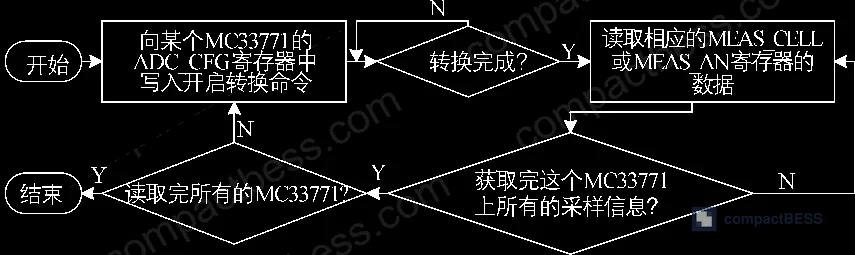
Bottom layer — BSU (Battery Sampling Unit): Built around the MC33771 analog front-end IC, this layer handles raw data acquisition: cell voltage, temperature, passive balancing, and local fault detection. Each MC33771 manages up to 14 series cells. Using daisy-chain communication, a single controller can cascade up to 15 MC33771 devices — that’s a maximum of 210 cells under one controller’s supervision.
Middle layer — BCU (Battery Control Unit): The BCU is built around an STM32F405RGT6, a 32-bit ARM Cortex-M4 processor running at 168 MHz with 1 MB of internal Flash. It manages daisy-chain communication with the BSUs below it, aggregates cell data, and passes it upward. The STM32F405 integrates 3× SPI buses and 2× CAN buses, which is exactly what this topology needs.
Top layer — BMU (Battery Management Unit): The BMU handles system-level coordination — responding to external requests, controlling charge/discharge relay sequences, and interfacing with upstream systems via CAN. The BMU and BCU share identical hardware boards; components are selectively populated based on which role the board fills. That’s a sensible cost and supply chain optimization.
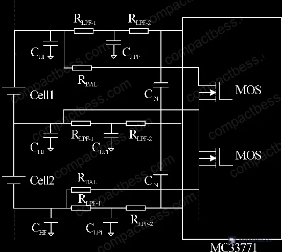
The daisy-chain approach between MC33771 devices eliminates the need for high-speed optocouplers and dedicated isolation power supplies at each node. Instead, a single HM2012NL isolation transformer handles signal transfer between cascaded ICs. An MC33664 signal converter translates the differential daisy-chain signal into SPI for the microcontroller. Differential signaling on the daisy-chain bus is important: in a pack with many series cells, ground potential differences between nodes are real and can corrupt measurements if not handled properly.
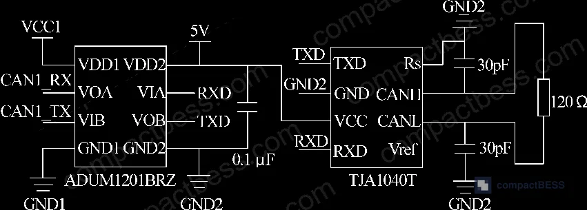
For CAN isolation between the BCU and BMU, an ADUM1201BRZ dual-channel magnetic isolator is placed between the STM32 CAN interface and the TJA1040T transceiver. A 120 Ω termination resistor on the CAN bus input suppresses reflections. These are standard practices — but not every contract manufacturer gets them right, and skipping the isolation stage is a failure mode we see in cheaper modules.
Comparison: Key IC Specifications in This BMS Design #
| Component | Role | Key Specification |
|---|---|---|
| MC33771 | Analog front-end / cell measurement | 14-channel voltage sampling, daisy-chain capable, 300 mA passive balancing |
| ADUCM331 | Current sampling processor | 20-bit ADC, ±200/+300 mV input range, 8 kHz max sample rate |
| STM32F405RGT6 | Main controller (BCU/BMU) | 168 MHz ARM Cortex-M4, 1 MB Flash, 3× SPI, 2× CAN |
| ADUM1201BRZ | CAN bus isolation | Dual-channel magnetic isolator, prevents ground-loop damage |
| TJA1040T | CAN transceiver | Standard CAN 2.0B, pairs with ADUM1201BRZ |
| MC33664 | Signal converter | Daisy-chain differential to SPI conversion |
BMS Measurement Accuracy: What the Test Data Actually Shows #
This is where the procurement decision lives.
Voltage Measurement Results #
Testing used two 14-series LTO packs. Cell voltages measured by the BMS host software were compared against an Agilent 6.5-digit multimeter — the reference instrument here is important. Across all 14 cells, the maximum measured voltage error was 2 mV. Eleven of fourteen cells showed zero error at the reported resolution. Three cells showed 1 mV error; one showed 2 mV.
| Cell # | BMS Reading (V) | Reference (V) | Error (mV) |
|---|---|---|---|
| 1 | 2.101 | 2.101 | 0 |
| 3 | 2.115 | 2.116 | 1 |
| 8 | 2.087 | 2.088 | 1 |
| 10 | 2.111 | 2.112 | 1 |
| 12 | 2.116 | 2.117 | 1 |
| 14 | 2.144 | 2.146 | 2 |
The full dataset across 14 cells shows a consistent pattern: error never exceeded 2 mV, and most readings were exact. For LTO chemistry specifically — which operates over a narrow voltage window of roughly 2.0 V to 2.7 V — a 2 mV ceiling is meaningful. Voltage-based SOC estimation on LTO is already challenging due to the flat discharge curve; compounding that with loose measurement accuracy makes it worse.
Current Measurement Results #
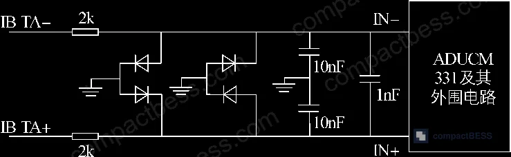
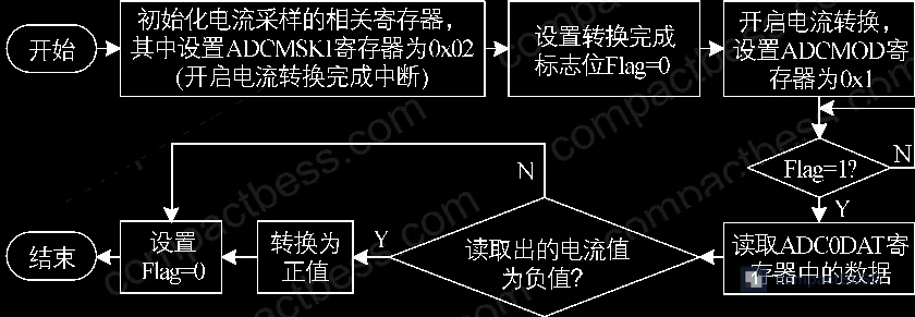
Current sampling uses a 500 A / 75 mV shunt resistor in the main circuit, read by an ADUCM331 current sampling IC. The ADUCM331 is a 32-bit ARM Cortex-M3-based processor with a 20-bit ADC, input voltage range of −200 mV to +300 mV, and maximum sampling frequency of 8 kHz. The chip communicates via SPI or UART and supports SWD programming.
An electronic load was used to create discrete discharge current steps from 0 A to 10.5 A. At each step, the BMS host reading was compared to the electronic load’s display value. Results:
- At 1 A, relative error was 2.0% — the highest in the test series
- From 4 A to 10.5 A, relative error ranged from 0.8% to 1.0%
- Absolute accuracy (error divided by the 1000 A full-scale reference) never exceeded 0.1% across all test points
- At 10.5 A, absolute accuracy was 0.09%
That 2.0% relative error at 1 A is worth noting. Low-current accuracy is often where shunt-based designs degrade — the signal voltage across the shunt is very small (0.15 mV at 1 A for a 500 A/75 mV shunt), so noise and offset dominate. The absolute accuracy metric tells a more useful story for system-level energy accounting: ±0.1% absolute against a 1000 A full-scale reference is commercially acceptable for grid-tied storage applications.
Honestly, most buyers over-specify current accuracy and under-specify voltage accuracy. A 1% current error on a 500 Ah pack means a 5 Ah accounting error per cycle — annoying but manageable. A 5 mV per-cell voltage error on an LTO pack with a flat discharge curve can throw your SOC estimate off by 10–15%, which has real operational consequences. The 2 mV ceiling this design demonstrates is the threshold worth insisting on.
Passive Balancing, Fault Detection, and SOC in Stationary Storage BMS Modules #
The MC33771 has passive balancing built in — it drives internal MOSFETs to bleed excess charge from higher-voltage cells, with a maximum balancing current of 300 mA. Balancing thresholds are configurable through the THALLCT register for voltage limits, and the THANxOT / THANxUT registers for temperature thresholds.
Fault detection is handled at the IC level. The MC33771 includes native detection for: overvoltage, undervoltage, overtemperature, undertemperature, balancing open-circuit, and short circuit. Each fault can be independently enabled or masked through the FAULT_MASKx register. This matters for system configuration: in some storage applications, you may want to mask certain non-critical faults that would otherwise cause nuisance trips during normal operation.
Most procurement teams don’t realize that the division of fault handling between the analog front-end IC and the main controller has changed significantly in recent BMS designs. Earlier architectures pushed all threshold logic to firmware on the MCU. Current devices like the MC33771 handle overvoltage and temperature detection in hardware — which means faster response times and fault detection that continues even if the MCU is momentarily busy. That’s a meaningful reliability distinction that never shows up in a spec sheet comparison.
SOC estimation was also validated in this test program. The paper notes that SOC functionality was tested and confirmed to meet operational requirements, though specific SOC error figures were not published in this dataset. For LTO chemistry, coulomb counting with periodic voltage recalibration is the standard approach; the flat discharge curve makes pure voltage-based SOC unreliable, which is why current sampling accuracy is the more critical parameter.
Practical Guidance for Buyers #
If you’re sourcing BMS modules for stationary energy storage — grid-tied systems, industrial UPS, telecom backup — the architecture described here reflects current best practice for medium-to-large pack configurations. The three-layer hierarchy is not overengineering; it’s a necessary response to the cell count and communication demands of systems with hundreds to thousands of series cells.
When evaluating suppliers, ask for measured test data, not just IC datasheets. The MC33771’s datasheet will tell you its nominal accuracy; what you need to know is what accuracy the supplier’s complete assembly achieves after their PCB layout, power supply design, and firmware calibration. Those are three places where a competent design can be degraded by execution failures.
Pay attention to isolation architecture. CAN bus isolation and daisy-chain differential signaling are not optional extras — they’re the difference between a BMS that works in a real pack under ground potential variation and one that produces corrupted data under those conditions. In supplier qualification, we have seen multiple BMS samples from vendors who skipped the CAN isolation stage to reduce board cost — and every one of those samples showed intermittent communication faults under high-voltage test conditions.
At compactbess.com, we connect global OEM buyers and energy storage integrators with verified Chinese manufacturers of BMS modules, lithium cell packs, and complete storage systems. If you’re at the point of comparing specific BMS architectures for your next procurement, our sourcing team can help you identify suppliers with the right technical depth and documented test data.
Need help identifying qualified suppliers for energy storage BMS modules? Talk to our sourcing team →
Supplier Qualification Questions #
- What is the per-cell voltage measurement error in your BMS module when validated against a 6.5-digit reference instrument, and can you provide a full 14-cell dataset showing individual cell errors rather than a single worst-case number?
- For current sampling, what is the absolute accuracy (expressed as a percentage of your shunt’s full-scale rating, e.g., 1000 A equivalent) at load points below 10% of full scale — specifically at 1 A or equivalent — where shunt signal voltage is lowest and noise contributions are largest?
- Your BMS uses a shunt for current measurement: what is the rated specification of the shunt (e.g., 500 A / 75 mV), and what is the ADC resolution and input voltage range of your current sampling IC? Can you share the part number?
- How many MC33771 (or equivalent analog front-end ICs) can your daisy-chain bus support per controller, and what is the total maximum cell count manageable from a single BCU without adding a second controller?
- What is the maximum passive balancing current your BMS can sustain per cell, and how are overvoltage and undertemperature fault thresholds configured — at the hardware register level on the AFE IC, or purely in MCU firmware?
Sourcing Checklist #
- [ ] Voltage measurement error is documented at ≤2 mV per cell, verified against a 6.5-digit reference multimeter or equivalent calibrated instrument across all cells in the pack
- [ ] Current sampling absolute accuracy is ≤0.1% of full-scale shunt rating, verified using a calibrated electronic load at a minimum of 8 discrete current steps
- [ ] CAN bus communication includes hardware isolation (magnetic or optocoupler) between the MCU CAN interface and the transceiver, with 120 Ω bus termination confirmed on schematic
- [ ] Daisy-chain communication uses differential signaling with an MC33664 or equivalent signal converter, and supports ≥14 series cells per AFE IC node
- [ ] BMS complies with IEC 62619 safety requirements for stationary battery systems, with test certificate available for review
- [ ] Passive balancing current is ≥300 mA per cell, with independent enable/disable control per cell via register configuration
- [ ] MCU runs at ≥100 MHz with ≥512 KB internal Flash, and integrates both SPI and CAN peripherals natively (not via external bridges)
- [ ] Fault detection for overvoltage, undervoltage, overtemperature, and short circuit is handled at the AFE IC hardware level, not solely in MCU firmware
Key Specifications Table #
| Parameter | Recommended Value | Verification Method |
|---|---|---|
| Per-cell voltage measurement error | ≤2 mV | Compare BMS host readings against Agilent 34401A or equivalent 6.5-digit multimeter across all series cells |
| Current sampling absolute accuracy | ≤0.1% of full-scale reference (e.g., ≤1 A error at 1000 A reference) | Sweep electronic load from 0 A to full rated current in ≥8 steps; log BMS vs. load display values |
| Current sampling ADC resolution | ≥20 bits | Request part number and datasheet for current sampling IC; confirm ADC spec |
| Passive balancing current per cell | ≥300 mA | Measure balancing bleed current directly at cell terminals with clamp meter during active balancing cycle |
| Maximum cells per AFE IC | 14 series cells | Confirm via AFE IC datasheet (e.g., MC33771 product brief) |
| Maximum cells per daisy-chain controller | Up to 210 cells (15× AFE ICs) | Request system architecture diagram showing daisy-chain cascade depth |
| MCU clock speed | ≥168 MHz (ARM Cortex-M4 class) | Request BOM or MCU part number; verify against manufacturer datasheet |
| CAN bus isolation | Magnetic isolator (e.g., ADUM1201BRZ class) in signal path | Request schematic segment showing CAN isolation topology |
Can’t find a supplier meeting these specs? Submit your requirements and we’ll match you within 48 hours.
Frequently Asked Questions #
Why is a three-layer BMS architecture preferred for stationary energy storage over a simpler two-layer design?
Stationary storage systems routinely contain hundreds to thousands of series-parallel cells — far more than an EV pack. A two-layer design concentrates too much processing load on a single controller, degrading real-time response. The three-layer hierarchy (BSU → BCU → BMU) distributes the load: the BSU handles raw analog acquisition locally, the BCU aggregates data from its cluster, and the BMU handles only system-level decisions and external communication. This prevents any single node from becoming a bottleneck. See more on BMS communication protocols for how data flows between layers.
What makes lithium titanate (LTO) cells particularly demanding for BMS voltage measurement accuracy?
LTO cells operate over a narrow voltage range — roughly 2.0 V to 2.7 V — and the discharge curve is very flat through most of the SOC range. This means small voltage errors translate into large SOC estimation errors. A 5 mV error on an NMC cell at mid-charge might correspond to <1% SOC uncertainty; on LTO, the same error can represent 10% or more. The ≤2 mV ceiling demonstrated in this validation is directly motivated by that chemistry characteristic.
Is a 500 A / 75 mV shunt appropriate for all stationary storage applications?
Not necessarily — it depends on your pack’s maximum continuous current. The 75 mV full-scale output at 500 A gives a shunt resistance of 150 µΩ. If your system routinely operates above 500 A, you need a lower-resistance shunt (which reduces signal voltage and demands higher ADC resolution). If your system rarely exceeds 50 A, a 100 A / 75 mV shunt gives you 10× better signal-to-noise at operating conditions. Shunt selection should be matched to your actual current profile, not just worst-case ratings.
Does passive balancing at 300 mA per cell meet the requirements for large-format energy storage packs?
For most stationary storage use cases, yes. Passive balancing at 300 mA is sufficient to correct cell-to-cell divergence during normal cycling, where spread between cells is typically small. Where 300 mA becomes limiting is in applications with significant cell mismatch from the start — aged cells, mixed batches, or packs that have seen uneven thermal history. In those cases, active balancing with higher transfer capability is preferable. For cell balancing architecture trade-offs, see our cell balancing active passive reference.
What communication standard should I require between the BMS and the site controller or inverter in a stationary storage application?
CAN bus (ISO 11898) is the baseline for most industrial BMS applications and is what this architecture uses between BCU and BMU layers. For grid-tied systems interfacing with inverters or SCADA, Modbus RTU or Modbus TCP is widely supported, and CANopen is common in European industrial applications. Require the supplier to confirm which protocols are supported at the BMU’s external interface and ask for the protocol implementation documentation — not just the claimed protocol name.
Published by compactbess.com Technical Team | Request a sourcing quote
Data source: Three-Layer Battery Management System Design and Validation for Stationary Energy Storage Applications, H. Liu et al., Journal of the Electrochemical Society, 2024
Content reviewed by dr.james.okafor | © compactbess.com — All rights reserved. Unauthorized reproduction prohibited.


