

TL;DR #
High-energy-density pouch cells (260–300 Wh/kg) using high-nickel NMC chemistry have a substantially elevated fire probability during nail penetration when fixture aperture drops below 20 mm combined with penetration speeds of 80 mm/s or faster. For procurement engineers, this means that safety validation protocols sourced from suppliers must specify test fixture diameter and nail speed explicitly — not just “pass/fail” against a hazard level. Before qualifying any high-nickel pouch cell above 210 Wh/kg, require suppliers to provide the short-circuit severity index (Λ) calculated from voltage drop and voltage recovery data, not just EUCAR Hazard Level classification.
Overview #
If you are evaluating high-energy-density pouch cells for EV packs, portable power stations, or industrial BESS modules, the nail penetration safety profile of your cell shortlist should weigh heavily in your qualification decision — arguably more than cycle life data at the early sourcing stage. Nail test outcomes are not just academic; they correlate directly with real-world failure modes from dendrite penetration and mechanical abuse in the field.
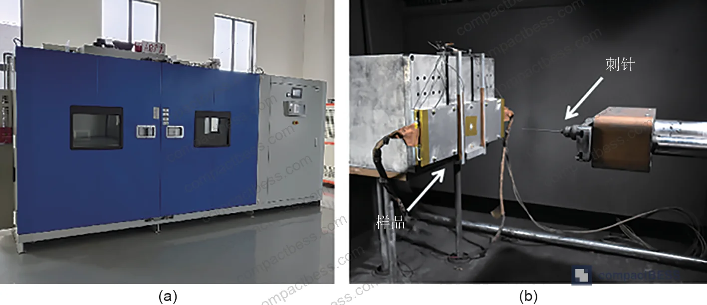
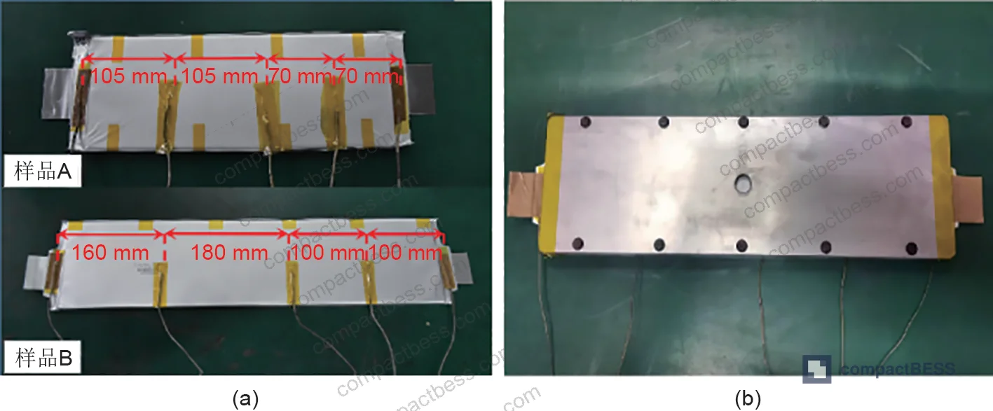
The data underlying this article comes from a controlled orthogonal test campaign conducted at a nationally accredited automotive testing institution in China, using two distinct high-nickel NMC pouch cell variants with energy densities in the 260–300 Wh/kg range. The test platform was purpose-built for high repeatability, with multivariate conditions covering fixture aperture, penetration speed, nail tip angle, and penetration position — 16 test groups in total, each condition run with duplicate samples. Voltage and surface temperature were logged continuously, and post-test cathode material was analyzed via XRD and electron microscopy to characterize internal damage.
This level of systematic, multi-variable nail testing is still rare in open supplier qualification packages. Most cell datasheets you will receive from Chinese manufacturers cite only a single pass/fail result under one set of conditions — which tells you almost nothing about how the cell behaves at the margins.
For buyers working on cell format and form factor selection decisions, the pouch format introduces specific structural considerations in nail safety that cylindrical and prismatic formats do not share, particularly around interlayer thermal conductivity and separator wrapping behavior.
Nail Penetration Variables That Determine Pouch Cell Thermal Runaway Risk #
The four test variables — fixture aperture, penetration speed, nail tip angle, and penetration position — do not all carry equal weight. Understanding which ones actually drive failure is what separates a competent cell qualification engineer from someone who just checks a box on a test report.
Fixture aperture is the dominant variable.
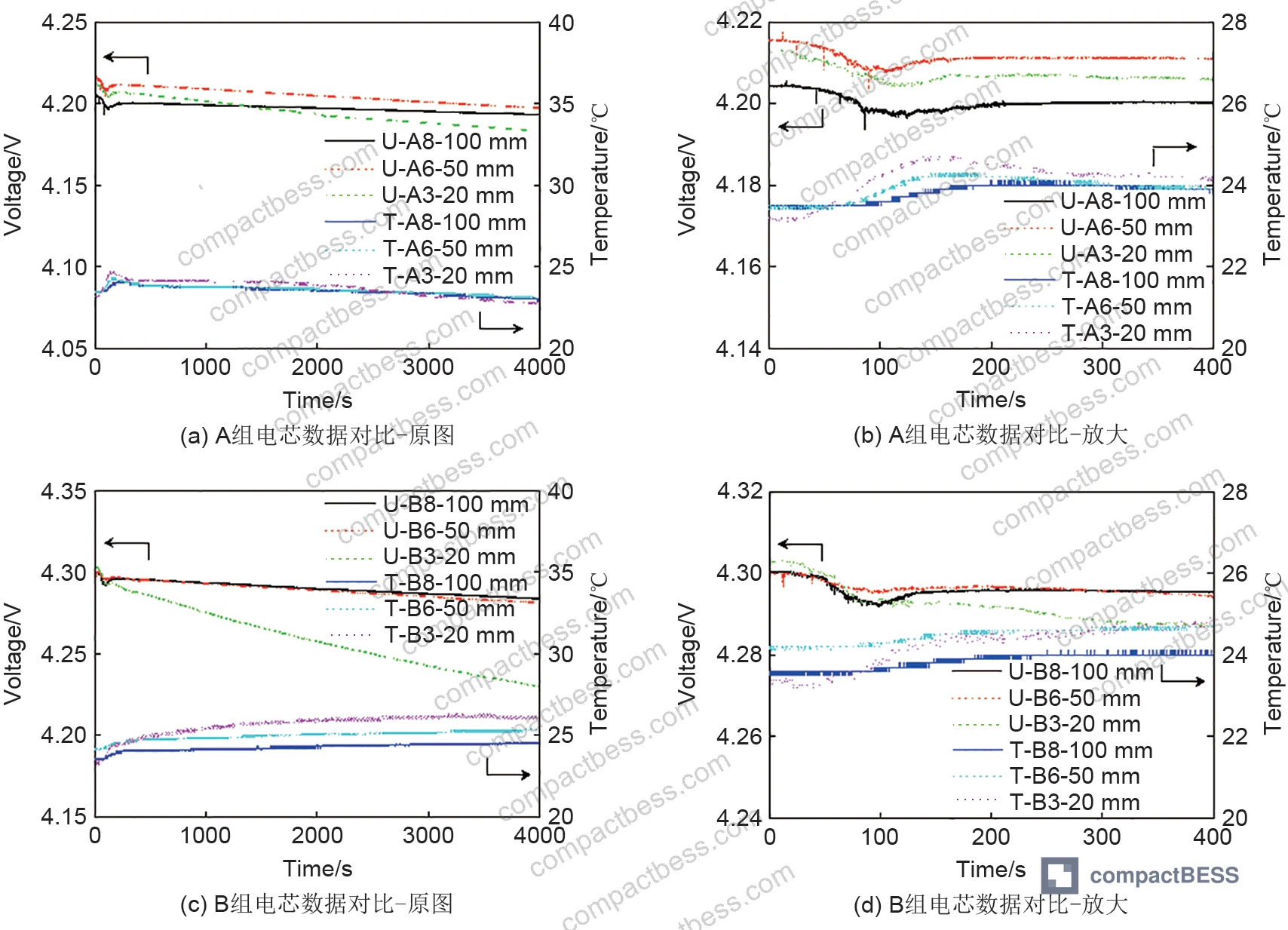
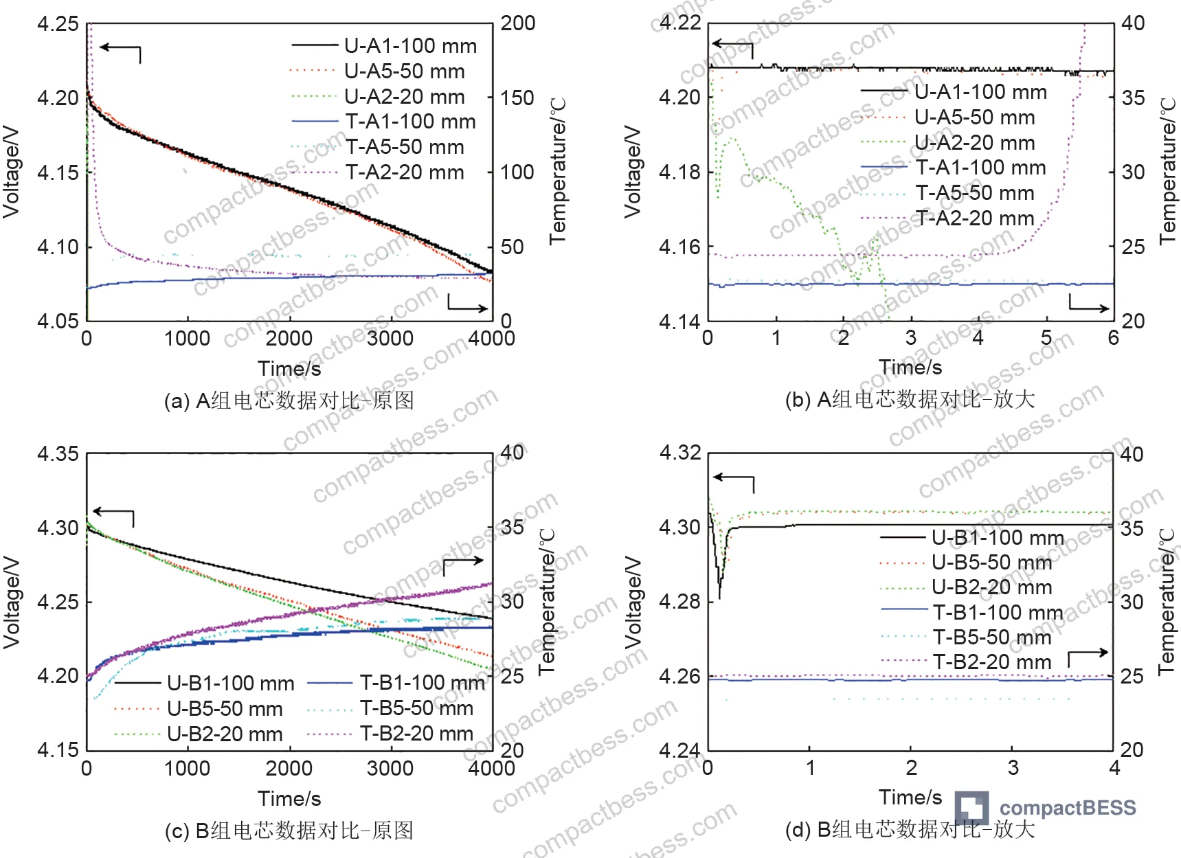
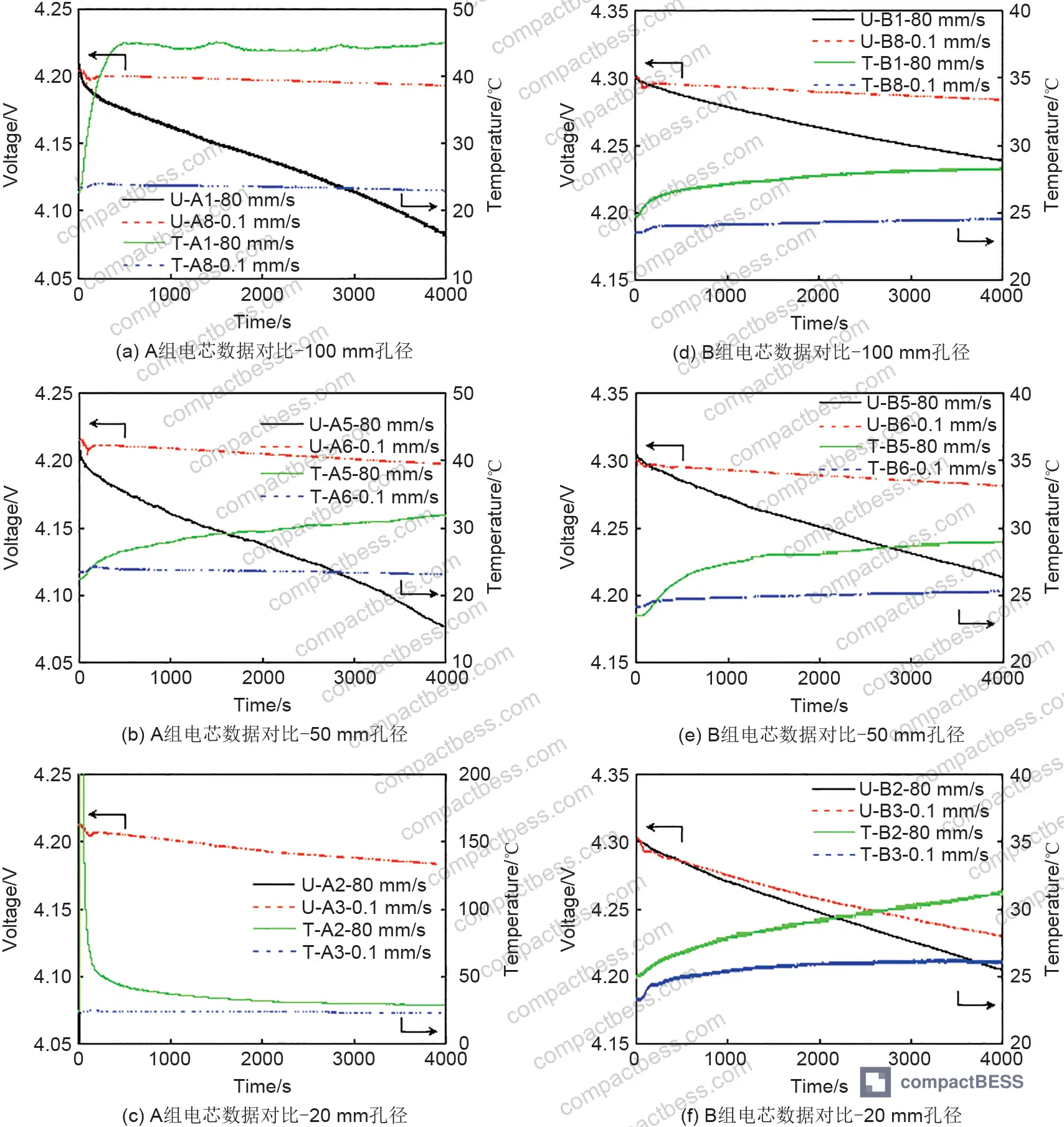
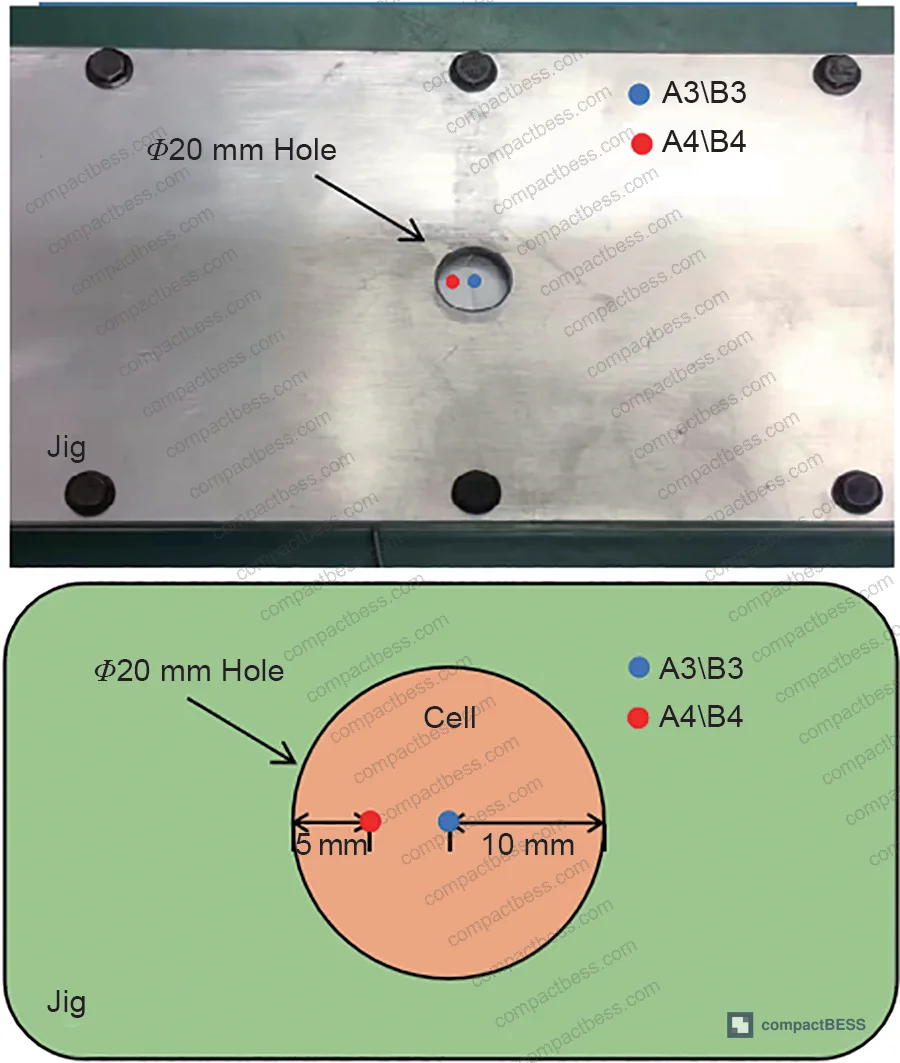
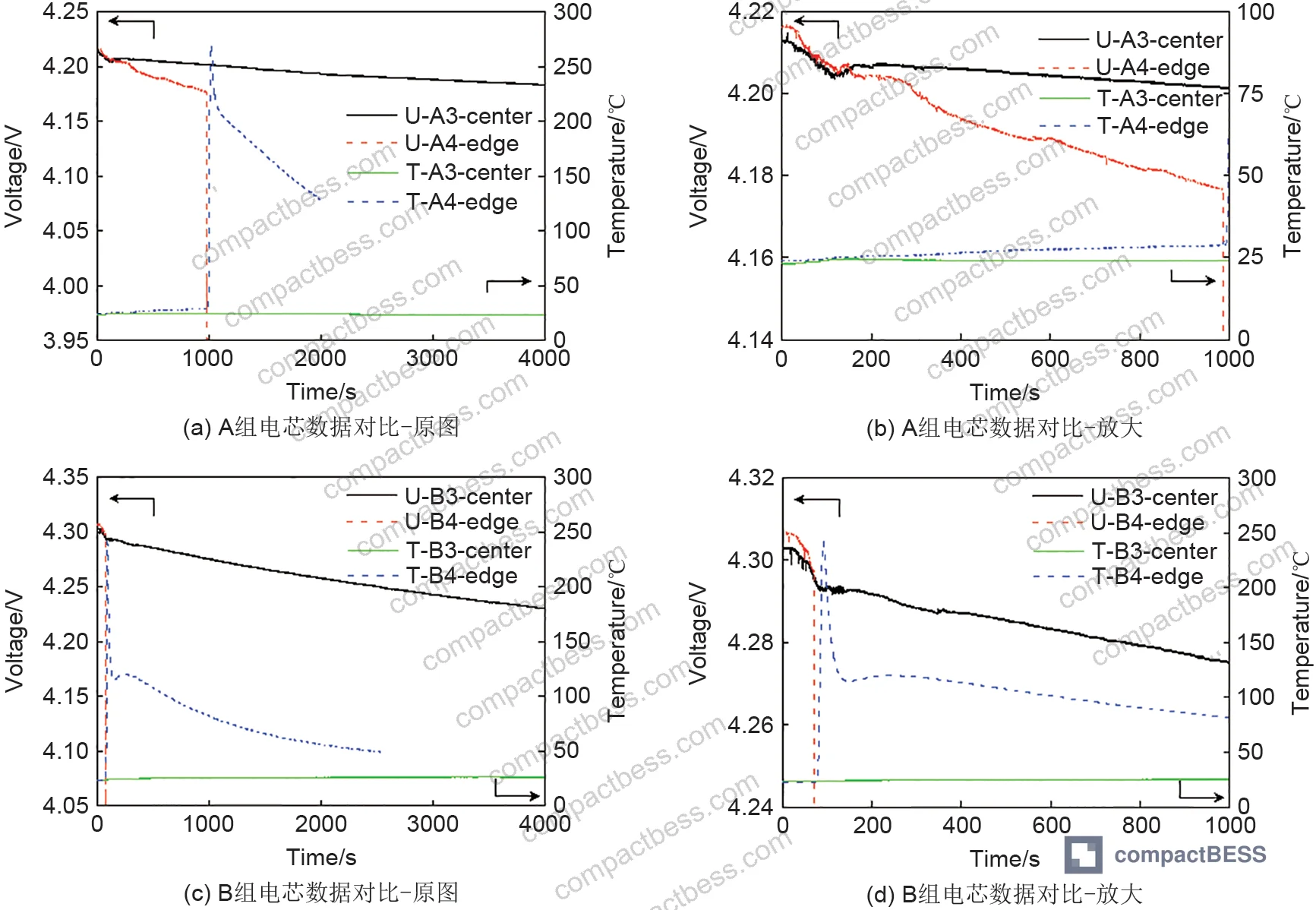
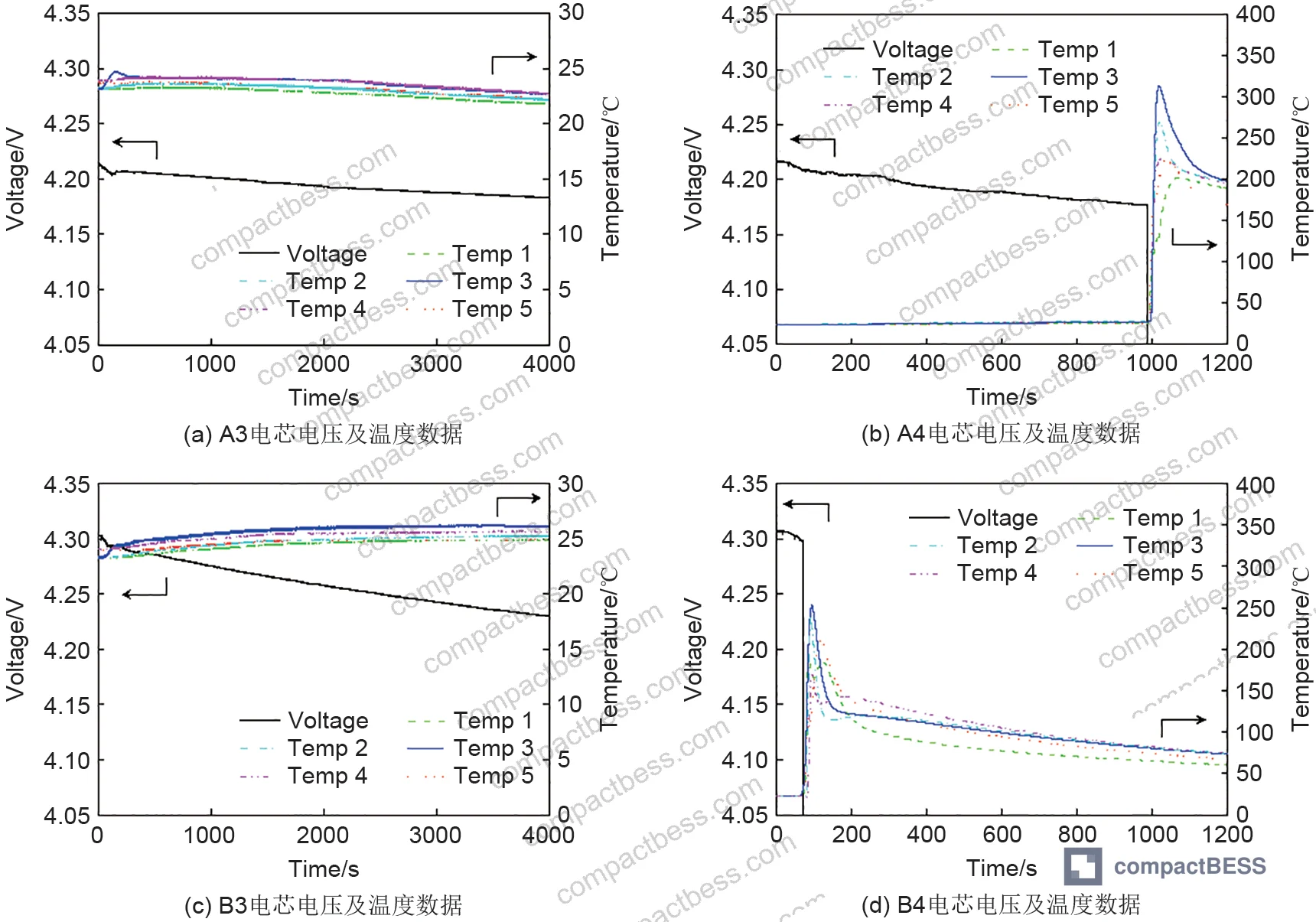
As fixture hole diameter decreases, the constraint on the cell surface increases, which concentrates internal short-circuit discharge energy. At apertures below 20 mm, the probability of thermal runaway and fire becomes substantially elevated for both 260 Wh/kg and 300 Wh/kg cells. At 100 mm aperture with 0.1 mm/s speed, both cell types recorded modest voltage drops (ΔV of 113 mV for Cell A, 69 mV for Cell B) and temperature rises of 9.4 °C and 3.5 °C respectively — manageable, stable, EUCAR HL3. Drop the aperture to 20 mm and run 80 mm/s speed: Cell A2 and Cell B4 both escalated directly to EUCAR HL5 — fire.
Penetration speed changes the separator’s ability to respond.
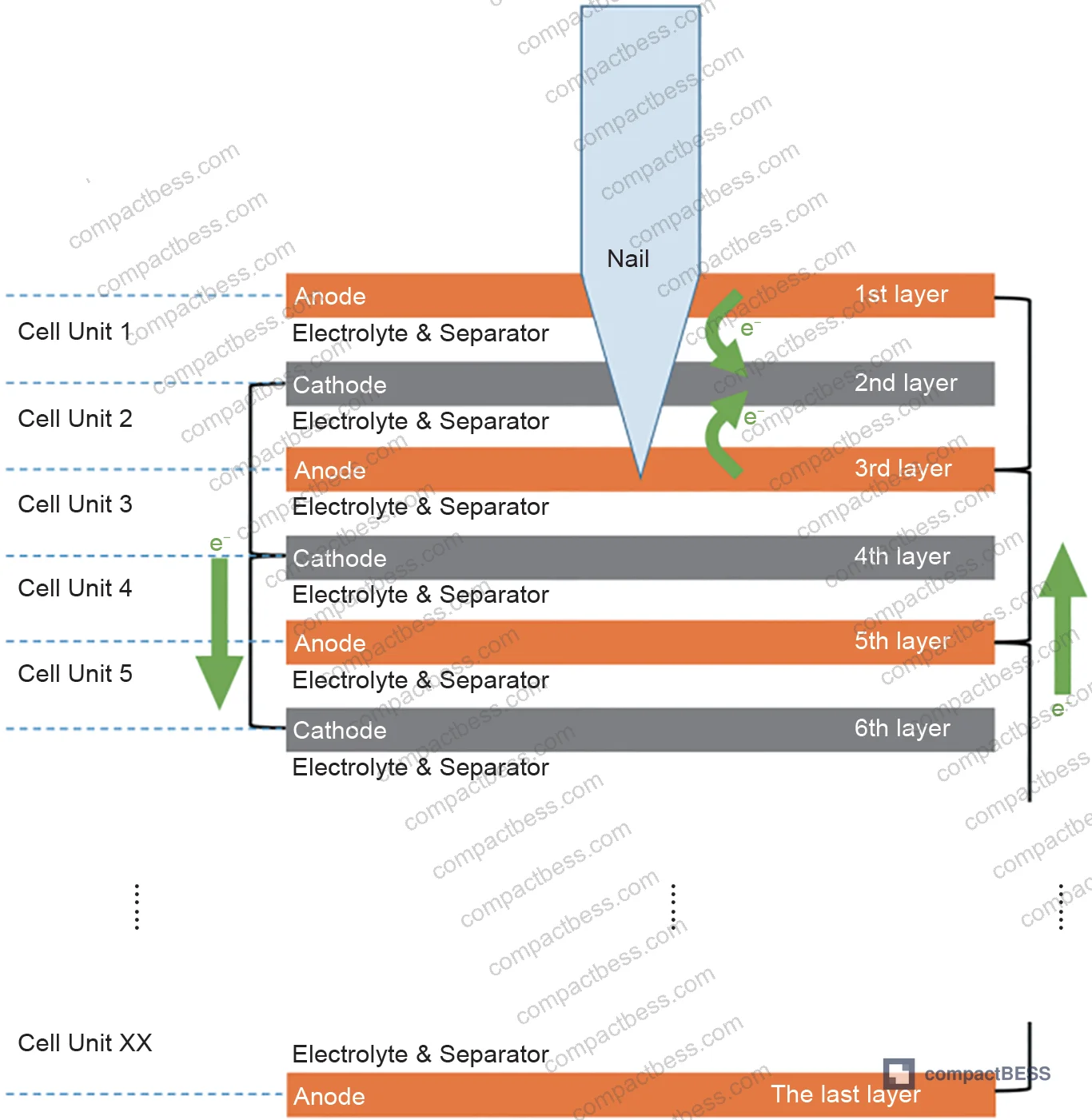
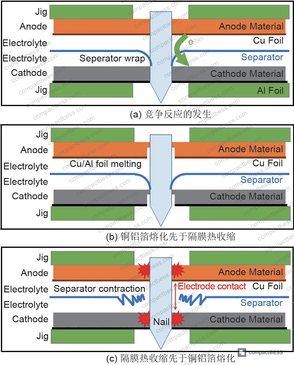
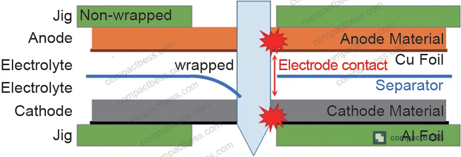
At 0.1 mm/s, the separator has time to deform, partially wrap around the nail, and maintain a physical barrier between anode and cathode layers. At 80 mm/s, the separator cannot stretch and wrap fast enough — direct metal-to-metal contact between electrode layers becomes likely, triggering acute internal short circuit. The voltage drop at 80 mm/s with a 20 mm aperture is essentially instantaneous, with no recovery curve — the cell fails before the external thermocouples register the event. This thermal lag is important: the pouch cell’s through-thickness (longitudinal) thermal conductivity measured at 1.18–1.27 W/(m·K) versus its in-plane (face) conductivity of 19.6–24.2 W/(m·K) means internal temperatures can be catastrophically high before the surface sensor reacts.
Nail tip angle: honestly, most buyers over-specify this.
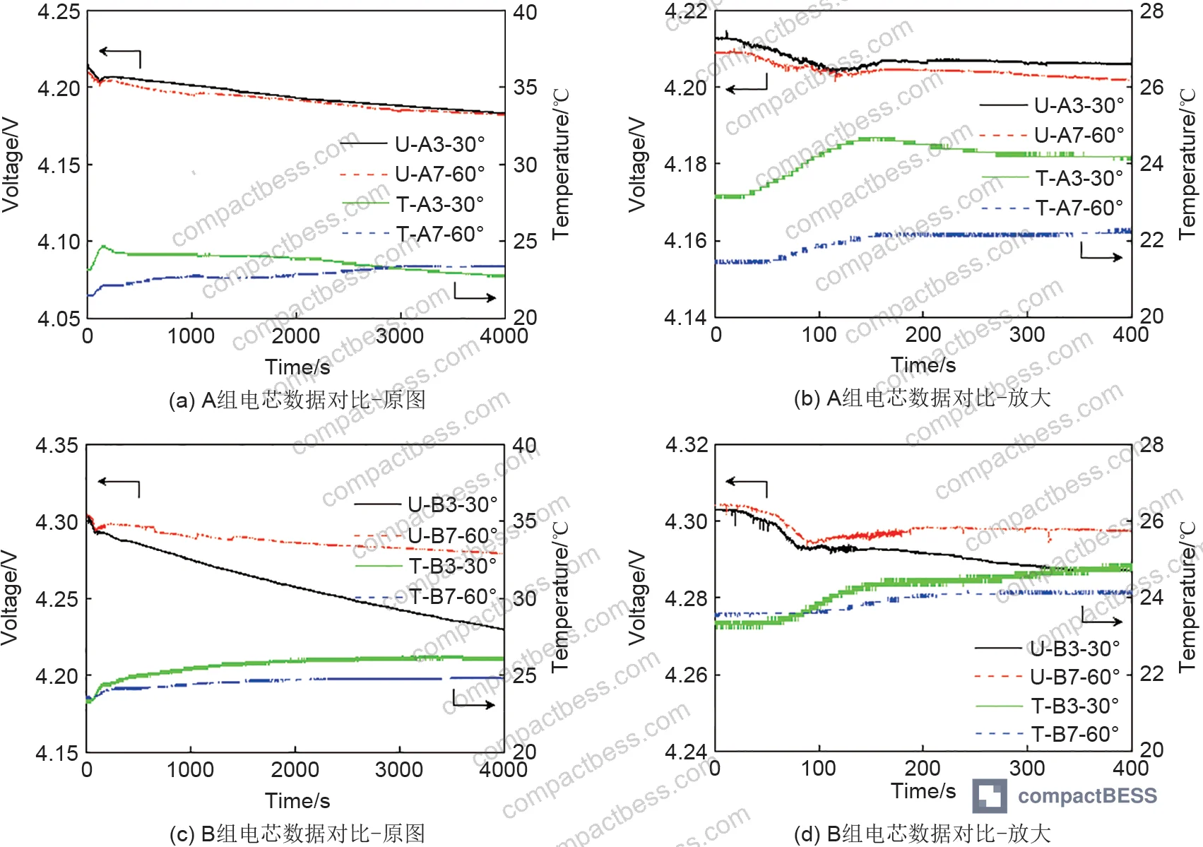
Changing nail tip angle from 30° to 60° produces no statistically significant difference in internal short-circuit energy discharge. The energy loss during penetration is essentially the same at both angles under equivalent fixture and speed conditions. Requiring a specific nail tip geometry in your procurement specification without controlling fixture aperture and speed is a waste of specification space — and suppliers know it. Focus your test requirements where the data says it matters.
Penetration position is the second critical variable — and it’s often overlooked.
When the nail does not enter at the center of the fixture aperture opening, fire probability increases sharply. This is because the separator’s wrapping and blocking effect — its ability to sleeve around the nail shaft and prevent electrode contact — depends on the nail entering perpendicular to a symmetric, unconstrained region of the cell face. Off-center penetration disrupts this geometry. This finding directly maps to real-world dendrite formation: dendrites do not grow uniformly, and localized internal shorts from asymmetric dendrite puncture are structurally analogous to off-center nail penetration.
Short-Circuit Severity Index: Why EUCAR Hazard Levels Fail High-Energy Cell Evaluation #
This is where the research makes its most practically useful contribution — and where most procurement teams are currently operating with inadequate tools.
Most procurement teams don’t realize that the EUCAR Hazard Level system, while widely referenced in standards from SAE J2464:2009 through UL 2580:2020, was designed for a different era of cell energy density. Applying HL0–7 classification to 260–300 Wh/kg cells collapses meaningful safety differentiation into noise.
In the 16-group orthogonal test matrix, 13 of the 16 test conditions produced an HL3 result — regardless of whether the voltage drop was 11 mV or 136 mV, regardless of whether temperature rose 0.6 °C or 22 °C. Only three conditions (A2, A4, B4) escalated to HL5. Everything else looked the same on a hazard level report. That is not acceptable for qualifying a cell that goes into a product responsible for consumer or industrial safety.
The short-circuit severity index (Λ) addresses this directly.
Λ = ΔVdrop × ΔVincrease
Where ΔVdrop is the maximum voltage drop from first nail contact to full nail stop, and ΔVincrease is the maximum voltage recovery in the same window. The product captures the intensity and character of the internal short-circuit event — specifically the current pulse that fuses the current collector foil. For the tested conditions, Λ values ranged from 14 (mV²) for the least severe (B8 at 100 mm aperture, 0.1 mm/s) to 460 mV² for the B2 condition (20 mm aperture, 80 mm/s) — a 33× difference that HL3 classification would flatten to the same result.
The Λ parameter allows ranking test conditions and comparing different products against each other quantitatively. For a procurement engineer building a cell qualification matrix, this means you can set a Λ threshold as a pass criterion — rather than accepting a binary HL3/HL5 result that obscures differentiation between cells.
For buyers evaluating compliance with IEC 62619:2022 Safety requirements for secondary lithium cells and batteries, notably that the standard’s nail penetration requirements do not currently specify fixture aperture diameter constraints. Your internal qualification standard should exceed what the published standard mandates, particularly for cells above 210 Wh/kg.
Need help identifying qualified suppliers for high-energy-density pouch cells? Talk to our sourcing team →
Post-Penetration Material Damage: What XRD and Microscopy Reveal #
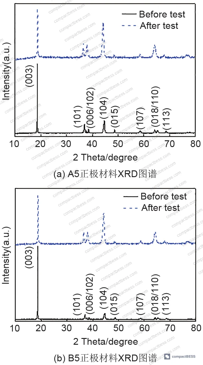
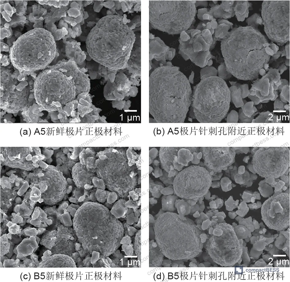
In supplier qualification, we saw post-test cathode analysis reveal damage that the surface-level test metrics did not predict. After nail penetration at high-severity conditions (20 mm aperture, 80 mm/s), the cathode material around the penetration hole showed characteristic transformation from layered phase to rock-salt phase in the high-nickel NMC material — a transition that occurs at temperatures exceeding 400 °C. This confirms that localized temperatures inside the cell during a severe internal short circuit far exceed what the external thermocouple records.
Specific findings from XRD analysis of cathode material scraped from the penetration zone:
- The I(003)/I(104) peak intensity ratio decreased significantly after severe nail penetration, indicating increased cation mixing in the layered structure
- The 2θ(018)–2θ(110) peak splitting degree was substantially reduced, confirming partial collapse of the layered crystal structure toward rock-salt phase
- These structural changes are consistent with local temperatures above 400 °C at the penetration site
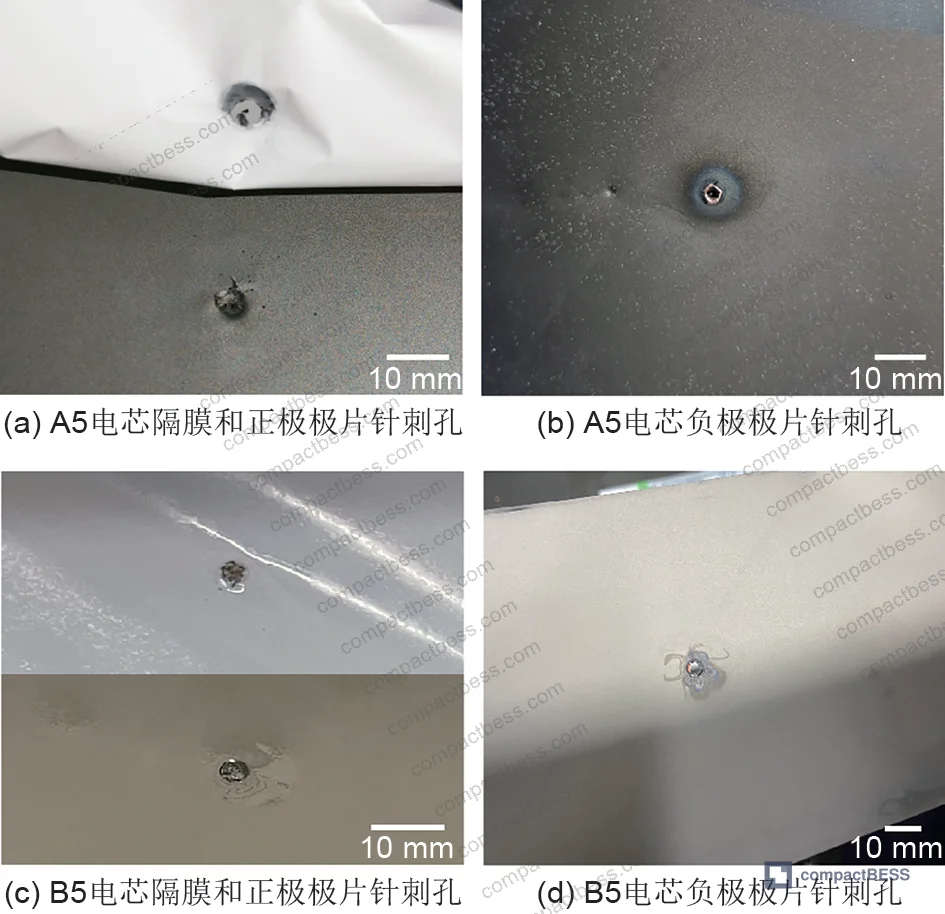
The aluminum current collector at the cathode was melted and blackened at the penetration site — the copper current collector at the anode remained visible in lower-severity tests but was also damaged in high-severity conditions. This current collector fusion is precisely the physical event that the Λ parameter is designed to capture in the voltage domain.
The in-plane thermal conductivity of the pouch cell measured 19.6–24.2 W/(m·K) in the face direction and only 1.18–1.27 W/(m·K) through the thickness. This 15–20× anisotropy is the reason external temperature sensors lag behind internal events. Temperature differences between the five thermocouple positions on the cell surface remained within 2 °C of each other even during fire events — meaning surface temperature monitoring alone cannot be used as an early warning indicator of internal thermal runaway in progress.
For buyers concerned with cycle life and degradation after mechanical abuse events, this cathode-level damage data is directly relevant: cells that survive a nail test at HL3 with a high Λ value may still have permanently compromised cathode structure at the penetration site, which will accelerate localized capacity fade.
For UN 38.3 transport certification requirements, the nail penetration test behavior also informs safe transport packaging design — cells with Λ values in the upper range of HL3 should be treated with extra caution in vibration and shock test design.
Practical Guidance for Buyers #
When you are qualifying a high-nickel pouch cell above 210 Wh/kg, the nail penetration test report you receive from a Chinese manufacturer is almost certainly insufficient. Here is what to require:
First, request that nail tests be conducted at a minimum of three fixture aperture sizes — including one below 20 mm — and at both slow (0.1 mm/s) and fast (≥80 mm/s) speeds. Any supplier who cannot provide this data either has not run the tests or does not want you to see the results. Both outcomes tell you something useful.
Second, require the Λ (short-circuit severity index) calculated from the voltage data for each test condition. This parameter is computable from standard voltage logging data — there is no equipment excuse for not providing it. If a supplier’s QC engineer has never heard of it, that is also diagnostic.
Third, treat external surface temperature data skeptically. Given the 15–20× thermal conductivity anisotropy between in-plane and through-thickness directions, a cell can be in active thermal runaway internally while the surface thermocouple is still reading a modest 5–10 °C rise. Do not accept “temperature stayed below 80 °C” as evidence of a safe nail test outcome.
For compliance with IEC 62133-2:2017 Safety requirements for portable sealed secondary lithium cells, the test conditions are a minimum floor — not an adequate qualification standard for high-energy-density cells. Your application-specific qualification should layer additional requirements on top, particularly fixture aperture specification and Λ reporting.
At compactbess.com, we work directly with verified Chinese manufacturers of pouch cell packs and BESS modules, and we help overseas OEM buyers establish cell qualification criteria that go beyond what standard datasheets provide. Our network covers suppliers with validated testing infrastructure and documented nail test data at the cell and pack level.
Need help identifying qualified suppliers for high-energy-density pouch cells? Talk to our sourcing team →
Supplier Qualification Questions #
- Can you provide nail penetration test data at fixture aperture diameters of 100 mm, 50 mm, 20 mm, and below 20 mm for your high-energy-density cells — and what is the EUCAR Hazard Level and measured Λ (ΔVdrop × ΔVincrease) value at each condition?
- What is the measured through-thickness (longitudinal) thermal conductivity of your pouch cell stack, and can you confirm whether it falls in the 1.18–1.27 W/(m·K) range typical of NMC pouch constructions — and how does your pack-level thermal management account for this anisotropy?
- At 80 mm/s penetration speed with a 20 mm fixture aperture, what percentage of your production batch cells avoid thermal runaway — and what design or process controls do you use to minimize fire probability at this condition?
- After nail penetration under HL3 conditions, can you provide XRD data showing the I(003)/I(104) peak intensity ratio and 2θ(018)–2θ(110) splitting degree for cathode material from the penetration zone, to confirm the extent of crystal structure degradation?
- What is the minimum separator wrap coverage percentage you specify around the nail shaft at 0.1 mm/s penetration, and how do you validate that off-center penetration (nail not entering at the center of the fixture aperture) does not disproportionately elevate fire risk in your cell design?
Sourcing Checklist #
- ☐ Supplier provides nail penetration test data at fixture aperture below 20 mm and confirms fire/thermal runaway probability at that condition with ≥2 duplicate samples per condition
- ☐ Nail test report includes both 0.1 mm/s and ≥80 mm/s penetration speed conditions, with voltage and temperature data logged for the full 1-hour observation window
- ☐ Supplier can calculate and report the short-circuit severity index Λ = ΔVdrop × ΔVincrease (in mV²) for each test condition, not just EUCAR Hazard Level classification
- ☐ Pouch cell through-thickness thermal conductivity is documented and confirmed within the 1.18–1.27 W/(m·K) range, distinguishing it from the in-plane value of approximately 20–24 W/(m·K)
- ☐ Cell energy density for NMC chemistry cells is confirmed ≥210 Wh/kg per GB industry specification, with full electrochemical characterization documentation
- ☐ Cathode material structural integrity post-nail-test is verified by XRD, with I(003)/I(104) ratio and 2θ(018)–2θ(110) splitting data available for HL3+ test conditions
- ☐ Nail penetration testing conducted in compliance with at least one recognized standard (IEC 62660-3:2022, SAE J2464, or UL 2580:2020) with full test parameters documented, including fixture aperture diameter and nail tip angle
- ☐ Supplier confirms test environment held at (25 ± 2) °C throughout penetration and 1-hour observation period, with thermocouple positions documented relative to the penetration site
Key Specifications Table #
| Parameter | Recommended Value | Verification Method |
|---|---|---|
| Energy density (high-nickel NMC pouch cell) | 260–300 Wh/kg | Discharge capacity test per IEC 62660-1, divided by total cell mass |
| Fixture aperture for nail penetration qualification | Test at ≥3 diameters including ≤20 mm | Nail penetration test per SAE J2464 or IEC 62660-3 with documented fixture spec |
| Through-thickness thermal conductivity | 1.18–1.27 W/(m·K) | Hot disk or laser flash measurement at 5+ positions on cell surface |
| Short-circuit severity index Λ threshold | Report value; flag cells with Λ > 200 mV² for additional review | Calculate from voltage logging: Λ = ΔVdrop (mV) × ΔVincrease (mV) |
| Penetration speed (fast test condition) | 80 mm/s minimum for high-speed scenario | Nail penetration machine speed calibration log |
| Surface temperature differential across cell during nail test | ≤2 °C between thermocouple positions (non-fire conditions) | 5-point thermocouple array at standardized positions per test setup |
| Cathode I(003)/I(104) XRD peak ratio (post-test) | Document baseline vs. post-nail degradation | XRD analysis of cathode material scraped from penetration zone |
Can’t find a supplier meeting these specs? Submit your requirements and we’ll match you within 48 hours.
References #
Data source: Nail Penetration Safety Characteristics of High-Energy-Density Lithium-Ion Pouch Cells: Effects of Test Variables and a Quantitative Severity Index, N. Yang et al., Journal of the Electrochemical Society, 2025
Frequently Asked Questions #
What is the short-circuit severity index (Λ) and why is it more useful than EUCAR Hazard Level for pouch cell evaluation?
The Λ index is calculated as the product of maximum voltage drop (ΔVdrop) and maximum voltage recovery (ΔVincrease) during the nail penetration event window — both measured in millivolts. In the 16-group test matrix evaluated here, 13 of 16 conditions all returned HL3 despite Λ values ranging from 14 mV² to 460 mV² — a 33× spread. Λ allows quantitative ranking of internal short-circuit severity and can be used to set numeric pass/fail thresholds in your cell qualification specification, something that binary hazard level classification cannot support.
Why does fixture aperture affect nail penetration outcomes more than nail tip angle?
Fixture aperture controls how much of the cell surface is constrained during penetration — smaller apertures concentrate internal short-circuit discharge energy and inhibit the separator’s ability to distribute stress. Nail tip angle (30° vs. 60°) was shown to produce essentially identical internal short-circuit energy loss under equivalent conditions. Fixture aperture is the dominant mechanical variable; nail tip geometry is secondary and often over-specified by buyers.
Can surface temperature monitoring reliably detect thermal runaway onset in pouch cells during nail penetration?
No. The through-thickness thermal conductivity of the pouch cell stack is approximately 1.18–1.27 W/(m·K), versus 19.6–24.2 W/(m·K) in the in-plane direction. This 15–20× anisotropy means internal temperatures at the penetration site can reach above 400 °C — sufficient to melt aluminum current collector foil — while external thermocouples show only modest readings. Temperature differences between the five thermocouple positions on the tested cells remained within 2 °C of each other even during active fire events. Surface temperature data should be treated as a lagging, low-resolution indicator only.
What energy density threshold makes high-speed nail penetration with small fixture apertures particularly hazardous?
Cells above 210 Wh/kg — specifically the 260–300 Wh/kg range tested here — show substantially elevated fire probability at fixture apertures below 20 mm combined with 80 mm/s penetration speed. Below this energy density threshold, the same test conditions are less likely to trigger thermal runaway because stored electrochemical energy available for discharge during the internal short-circuit event is lower. The Chinese industry specification explicitly requires ≥210 Wh/kg for NMC-type energy cells, which means essentially all commercially competitive cells today fall in this risk zone.
Does penetration position (center vs. off-center) affect fire probability, and should this be specified in a supplier qualification protocol?
Yes, significantly. Off-center penetration — where the nail does not enter at the geometric center of the fixture aperture opening — substantially increases fire probability compared to centered penetration under otherwise identical conditions. This is because the separator’s ability to wrap around and sleeve the nail shaft depends on symmetric, unconstrained membrane geometry. Off-center entry disrupts this wrapping mechanism and allows direct electrode-to-electrode contact. Buyers should specify centered penetration as the baseline condition but require off-center penetration testing as a supplementary robustness check, particularly if the cell will be used in applications with vibration or mechanical stress risk.
Published by compactbess.com Technical Team | Request a sourcing quote


