

TL;DR #
High-voltage cascaded multilevel PCS topology delivers the highest operational efficiency and flexible battery control among all compared configurations, but its component count and cost make it unsuitable for anything below utility-scale deployments. Buyers specifying PCS for systems above 1 MW need to match topology class to their voltage level and grid interconnection requirements — selecting a two-level topology for large-scale projects is a costly mistake that forces expensive step-up transformers and limits battery management flexibility. Before issuing any RFQ, confirm the PCS topology class your application actually requires, then qualify suppliers against the switching stress and efficiency thresholds documented in this guide.
Overview #
Most procurement teams evaluate PCS units on nameplate power rating and price — and miss the topology decision entirely until they’re deep into system integration, which is where expensive redesigns happen. The analysis underlying this article comes from a university-affiliated energy storage engineering research center that systematically evaluated two-level, three-level, and multilevel converter topologies across switching frequency ranges, component stress conditions, and modular grid interconnection scenarios. The work covered representative topologies from the 500 kW scale up to hundred-megawatt-class cascaded systems, making it one of the more comprehensive structural comparisons available for engineering procurement reference.
The core finding is that no single topology dominates across all application scales. Each architecture involves real tradeoffs in switch count, voltage stress, control complexity, and system cost — and these tradeoffs map directly to procurement specifications that buyers either get right at the design stage or pay to fix later.
This guide translates those findings into actionable evaluation criteria. Whether you’re sourcing PCS units for a containerized battery storage system, a grid-tied industrial UPS, or a utility-scale storage plant, understanding the topology hierarchy is the first qualification filter you should apply.
For context on how battery pack architecture connects to PCS design requirements, see our Cell Formats & Form Factors technical library, and for BMS integration considerations that directly affect PCS topology selection, the Series & Parallel Configuration section covers the cell-side constraints in detail.
Two-Level PCS Topology: Where It Works and Where It Doesn’t #
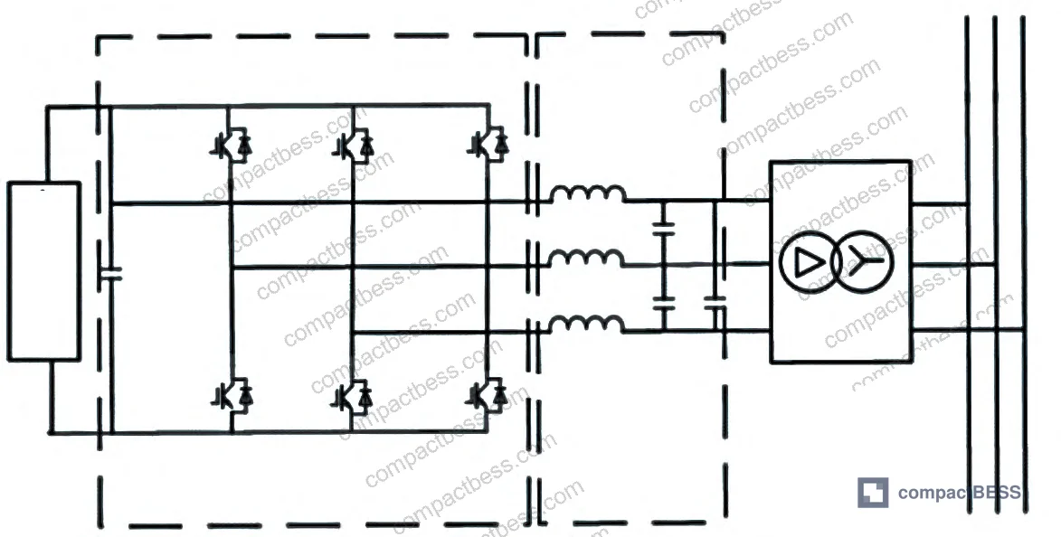
The two-level topology is the baseline architecture. It’s the most widely deployed PCS configuration at the 500 kW scale in current electrochemical storage projects, and the single-circuit full-bridge variant runs at operational efficiency exceeding 98% under standard conditions. That efficiency number looks attractive on a datasheet, but it comes with structural constraints that buyers often underestimate.
The fundamental limitation is DC voltage. Battery string voltage at practical series configurations stays below the AC grid interconnection level, so a step-up transformer is mandatory. That transformer adds cost, physical volume, and an additional failure point. For large installations, it also means working with industrial-frequency transformers rated for the full system power — equipment that is neither cheap nor easy to source with short lead times.
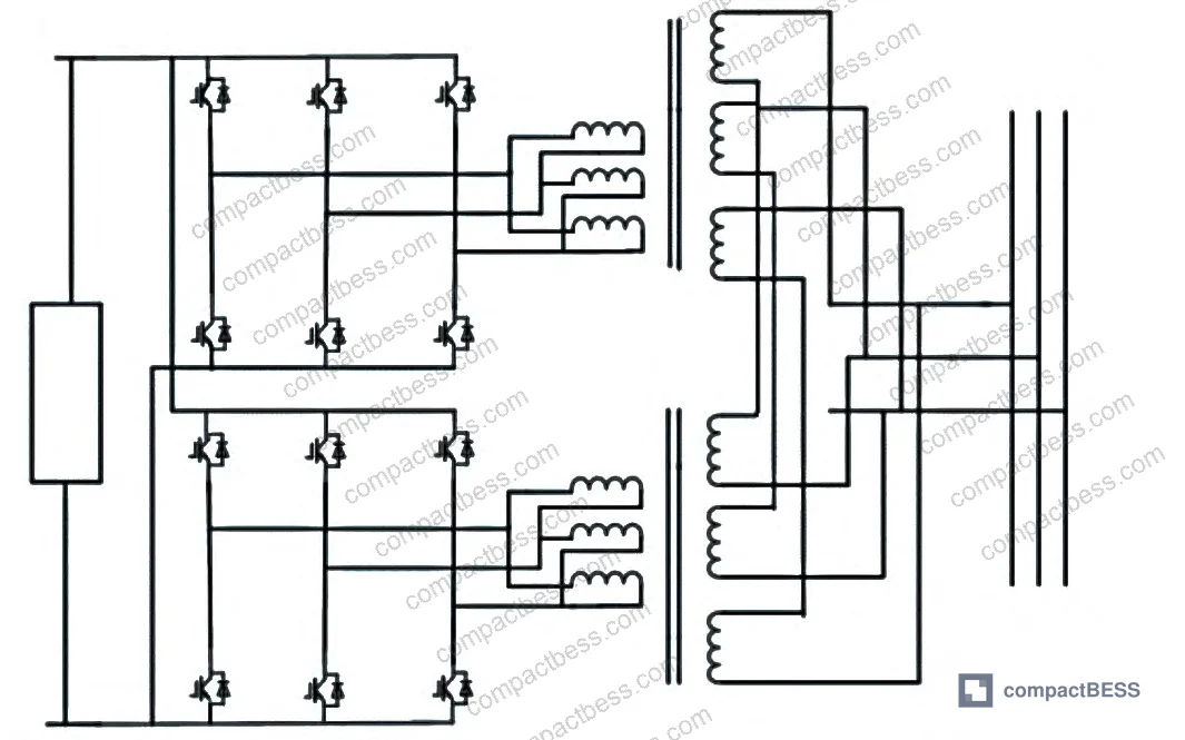
The multiplexed (multi-winding) full-bridge two-level variant addresses capacity limitations by combining 2 or more single-circuit full-bridge inverter units through transformer series coupling. This configuration reduces output voltage harmonic content and pushes single-machine capacity above the 500 kW ceiling. The tradeoff: control complexity increases substantially, and paralleling multiple two-level units introduces circulating current risk and system instability potential that doesn’t exist in a single-unit installation.
Honestly, most buyers over-specify the transformer requirements for two-level systems without realizing that the transformer itself is what’s constraining the total system efficiency. A 98% efficient inverter stage paired with a 97% efficient transformer gives you a system efficiency closer to 95% — and that’s before you account for filter losses. When you’re evaluating two-level PCS suppliers, ask for full system efficiency figures, not just inverter stage efficiency.
Single-machine capacity for two-level topologies generally stays below 500 kW due to series battery count restrictions and switching device on-state losses. This is a hard architectural ceiling, not a supplier capability issue.
Three-Level PCS Topology: I-Type vs T-Type Performance Comparison #
The shift to three-level topologies was driven by market demand for higher single-machine capacity and improved output power quality. By chopping the DC bus into three voltage states — positive, zero, and negative — three-level PCS designs reduce switching device losses, shrink filter component sizes, and enable higher output voltages without the harmonic penalty that limits two-level designs.
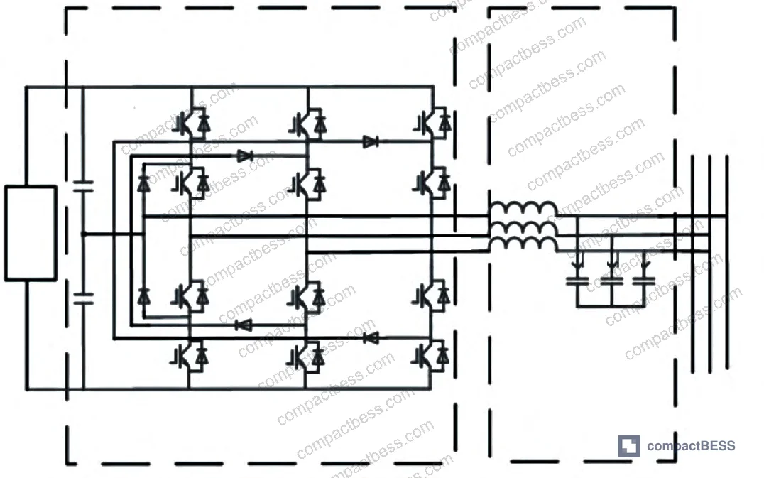
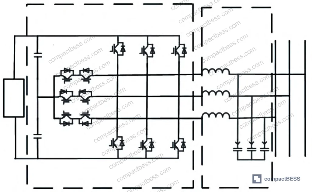
Two configurations dominate: the I-type (diode-clamped) and the T-type (bidirectional switch). Their structural performance comparison from controlled evaluation is summarized below.
| Parameter | I-Type Three-Level | T-Type Three-Level |
|---|---|---|
| Diode count | 12 | Fewer (no clamping diodes required) |
| Switch device count | 12 | 12 |
| Switch voltage stress | Ui/2 per device (half DC bus voltage) | Higher — up to full Ui on outer devices |
| Drive circuit complexity | Higher — strict timing sequences required | Lower — no strict interlock timing |
| Power loss at switching frequency >16 kHz | Higher | Lower |
| Power loss at switching frequency <16 kHz | Lower | Higher |
| Control reliability | Lower — more susceptible to timing errors | Higher |
Can’t find a supplier meeting these specs? Submit your requirements and we’ll match you within 48 hours.
The key differentiation point is switching frequency. Below 16 kHz, I-type topology has the efficiency advantage. Above 16 kHz, T-type pulls ahead on losses. This crossover point is directly relevant to buyers specifying PCS units for applications with strict harmonic distortion limits — higher switching frequencies reduce output THD but shift the loss balance toward I-type disadvantage.
I-type’s 12 switch devices each see only half the DC bus voltage (Ui/2), which is the architecture’s main safety advantage. T-type outer devices must withstand the full bus voltage, which drives up the voltage rating requirement for those components and the associated cost.
In supplier qualification, we saw that T-type topologies from less experienced manufacturers frequently showed reliability issues traced back to inadequate voltage margin on outer switch devices. The T-type architecture’s reduced timing complexity does not eliminate the need for proper device derating — it just changes where the engineering challenge sits.
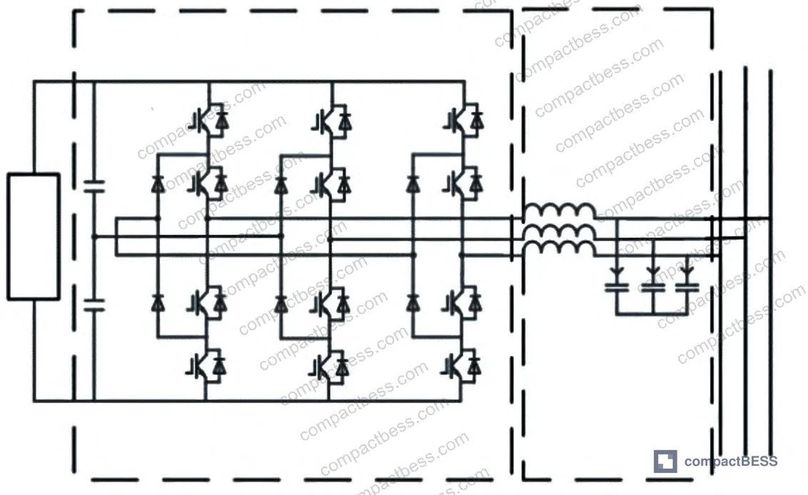
Most procurement teams don’t realize that the three-level topology revision toward T-type dominance in the mid-power range (500 kW to 2 MW) happened largely because of IGBT cost reductions that made the higher-voltage outer devices economically viable. Before that shift, I-type was the default — and many datasheets still reflect older design generations. Always confirm which topology generation you’re actually buying.
IEC 62619:2022 Safety requirements for secondary lithium cells and batteries provides the safety framework that both three-level topology variants must operate within when connected to lithium battery systems — relevant particularly for protection against overvoltage events that asymmetric switch stress can trigger.
Multilevel PCS Topology: Diode-Clamped, Flying Capacitor, and Modular Configurations #
Multilevel topologies enter the picture when system requirements push beyond what three-level designs can deliver — typically above 2 MW, or where direct high-voltage grid interconnection without step-up transformers is the target.
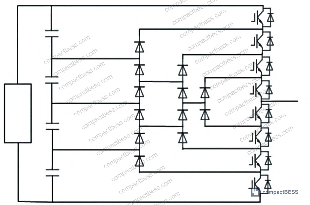
Three classical multilevel topologies are in active use:
Diode-clamped multilevel: Scales output voltage levels by stacking switch devices and clamping diodes. The engineering problem is that clamping diodes closer to the inner switching positions experience asymmetric reverse voltage stress. This uneven stress distribution is a known failure mode — devices in inner positions see less stress, outer positions see more, and the capacitor voltage balancing becomes progressively harder to maintain as level count increases. Beyond five levels, this architecture becomes difficult to implement reliably without active balancing circuits.
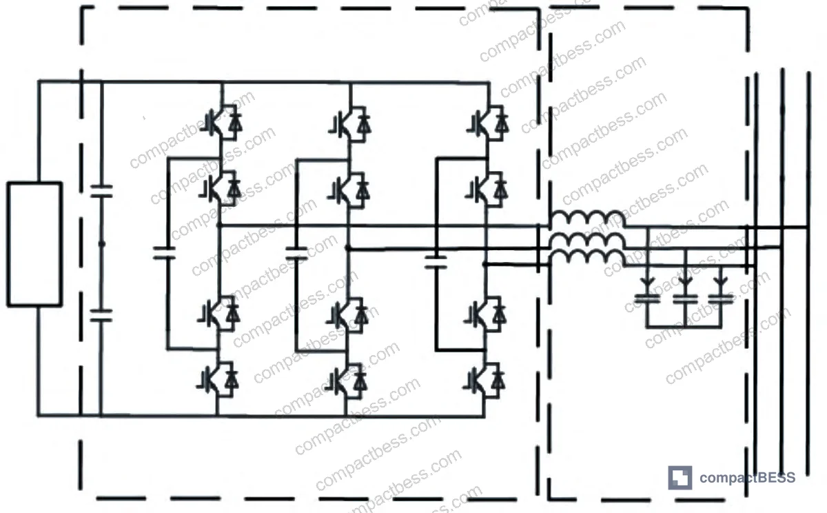
Flying capacitor multilevel: Replaces clamping diodes with floating capacitors that store intermediate voltage levels. This eliminates the asymmetric diode stress problem but introduces capacitor voltage balancing as an ongoing control challenge. The capacitor count scales with level number, adding cost and volume. One improved variant based on Zeta converter topology achieves input-side parallel battery connection with output-side series filter combination — effectively decoupling the battery voltage from the inverter output voltage specification.
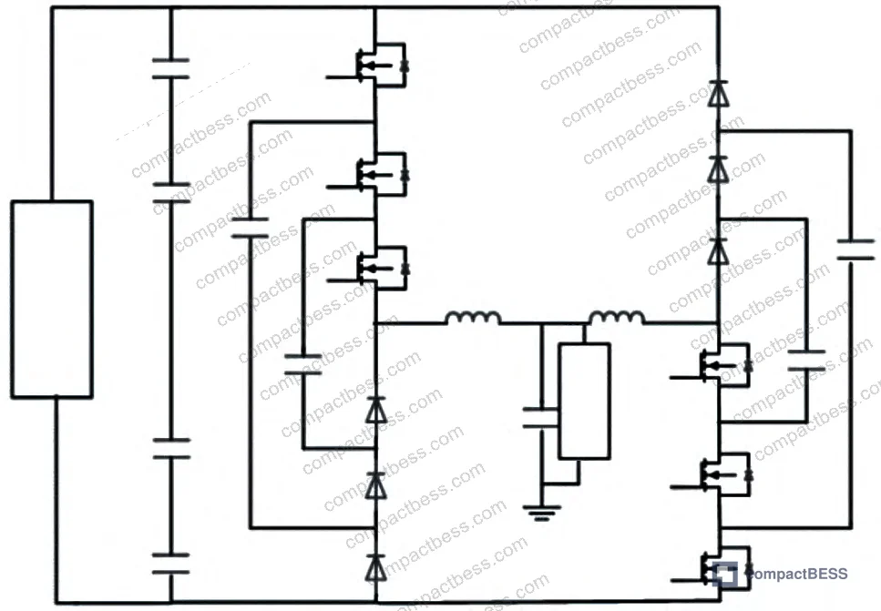
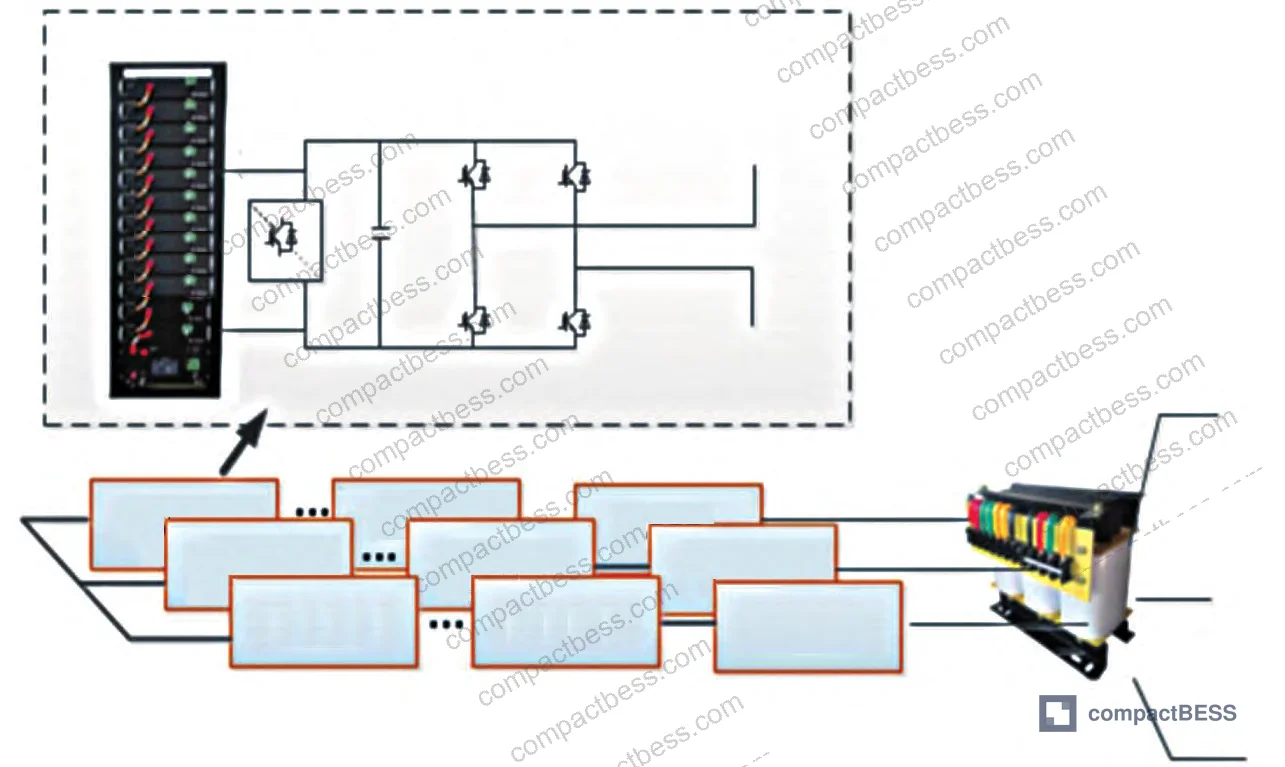
Cascaded H-bridge (CHB) multilevel: The dominant architecture for high-voltage, high-power applications. Individual H-bridge modules are series-connected on the AC side, with each module powered by a separate battery string. A dual flying capacitor nine-level implementation reduces switch count and floating capacitor count by half compared to a conventional nine-level design, while the increased level count simultaneously reduces output voltage harmonic content.
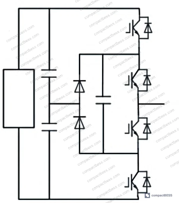
For grid-scale deployments, the modular PCS topology comparison across application scenarios is critical. The table below summarizes the four main modular configurations:
| PCS Topology Configuration | Key Advantages | Key Limitations |
|---|---|---|
| Low-voltage low-power distributed step-up grid-tied | Modular BMS integration, fault redundancy, low device voltage rating | Inter-module circulating current, control coordination difficulty, instability at large parallel counts |
| Low-voltage high-power centralized step-up grid-tied | Simple structure, lower cost, easy switch control | Low efficiency, safety concerns, cumbersome BMS management |
| High-voltage high-power cascaded | Flexible control, high efficiency, good safety | High component count, high cost, complex switch control |
| Intelligent string-connected grid-tied | Improved stability, optimized energy management | Requires additional DC-side battery storage modules per inverter |
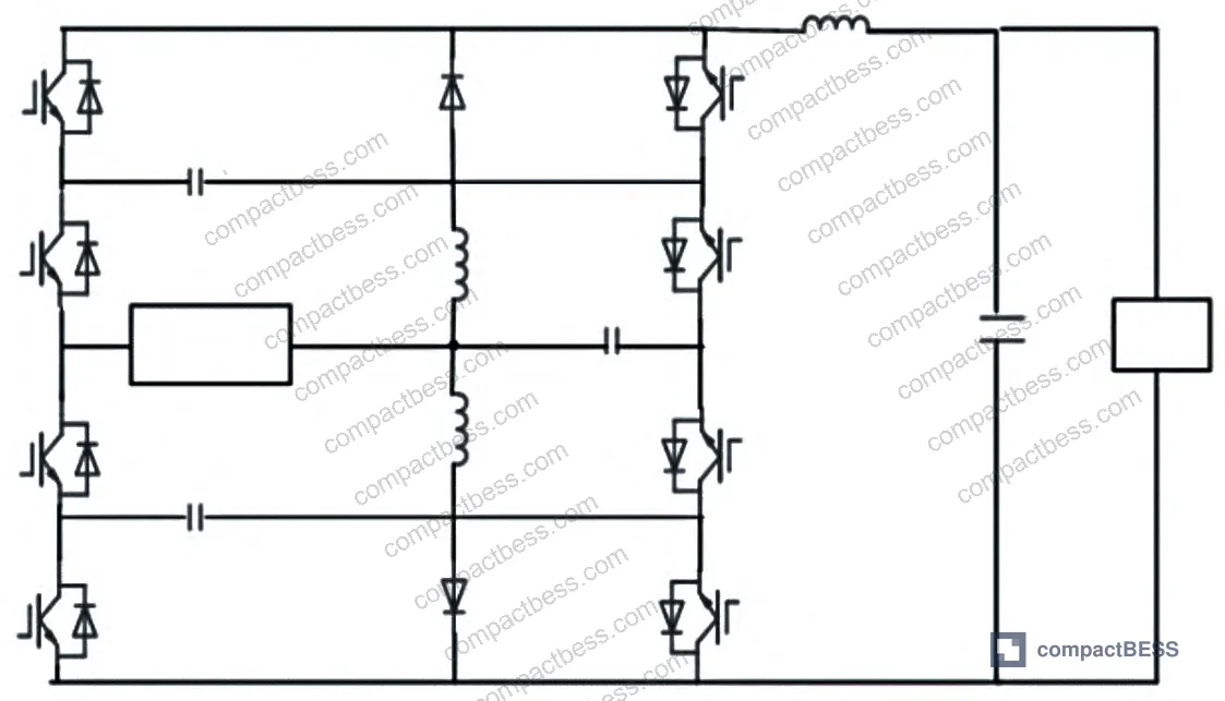
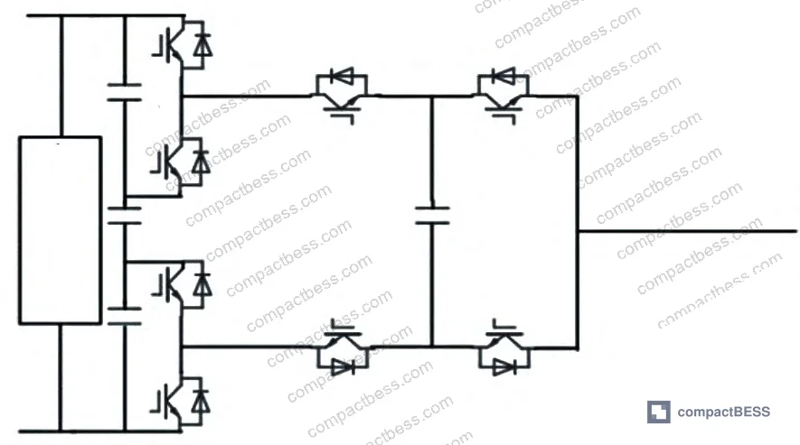
The cascaded high-voltage topology is currently the primary direction for research and commercial deployment at the 10 MW+ scale. Its ability to flexibly regulate individual battery module groups substantially reduces the BMS workload and improves whole-system energy management efficiency — but the component count (numerous switching devices and capacitors per module) keeps unit costs high.
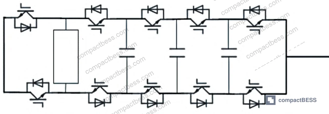
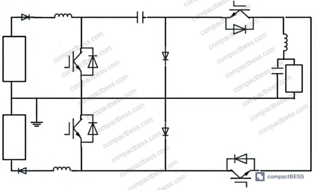
For the dual flying capacitor nine-level design, the quantified advantage is clear: switch device count and floating capacitor count are each reduced by 50% compared to a conventional nine-level flying capacitor design, while output voltage harmonic components decrease as level count increases.
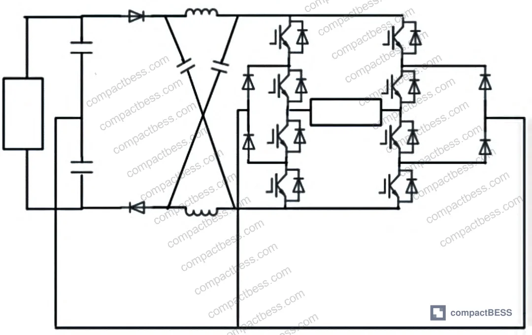
For AC Charging & Inverter Integration applications, multilevel topologies directly affect harmonic injection into the AC grid — a parameter that grid operators are increasingly enforcing, particularly in European and North American interconnection agreements.
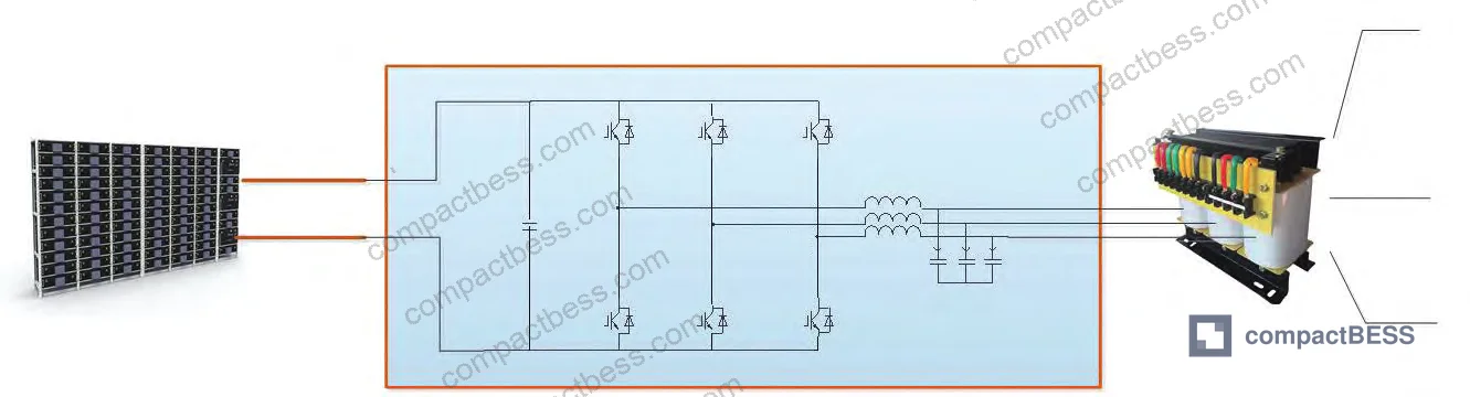
Practical Guidance for Buyers #
The topology selection decision needs to happen before the battery pack specification is finalized — not after. Battery string voltage, series configuration depth, and BMS architecture are all constrained by the PCS topology you choose. Getting this sequence backward is one of the most common and expensive integration errors in battery storage project procurement.
For systems below 500 kW, the single-circuit full-bridge two-level topology at >98% inverter efficiency is the practical standard. Specify it explicitly and ask for full system efficiency inclusive of the step-up transformer. For mid-range systems between 500 kW and 2 MW, three-level T-type topologies are the current cost-performance optimum at switching frequencies above 16 kHz. For utility-scale projects, cascaded multilevel topologies dominate, and the qualification focus shifts to module-level control capability and BMS integration flexibility.
IEEE 2030.2.1 Guide for Design, Operation, and Maintenance of Battery Energy Storage Systems provides the operational framework that these PCS topologies must conform to — particularly relevant for buyers integrating storage into regulated grid environments.
At CompactBESS, we work with OEM developers and energy storage integrators across North America, Europe, and Southeast Asia to connect them with verified Chinese manufacturers who supply PCS units, BMS modules, and complete containerized storage systems. If your project specifications are already defined, we can match you to manufacturers with confirmed production experience at your required topology and power level.
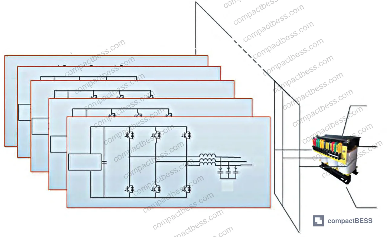
Compliance with IEC 61960-3 Secondary lithium cells and batteries for portable applications is a baseline documentation requirement for the battery cell side of any PCS integration — buyers should confirm this certification covers the specific cell form factor being used before the PCS interface design is finalized.
Need help identifying qualified suppliers for PCS units or integrated battery storage systems? Talk to our sourcing team →
Supplier Qualification Questions #
- For your three-level PCS product, what is the switching frequency crossover point between I-type and T-type topology efficiency — and at what specific switching frequency does your design operate? Confirm whether power loss at frequencies above 16 kHz has been characterized by switching frequency sweep testing.
- In your two-level full-bridge PCS at 500 kW, what is the measured full-system efficiency inclusive of the step-up transformer stage — not just the inverter stage efficiency? Provide test data showing operational efficiency at rated load.
- For cascaded multilevel PCS modules, how many switching devices and floating capacitors are used per H-bridge module, and how does this compare to a conventional nine-level design? We expect to see at least a 50% reduction in both parameters for a dual flying capacitor nine-level implementation.
- In your diode-clamped multilevel topology designs, how is asymmetric reverse voltage stress across inner versus outer clamping diodes managed, and what is the voltage derating factor applied to inner-position devices relative to outer-position devices?
- For modular PCS topologies used in distributed low-voltage grid-tied applications, what is your inter-module circulating current specification, and what isolation method — isolated DC/DC converter or other means — is used to suppress circulating currents between parallel storage units?
Sourcing Checklist #
- ☐ Supplier provides full-system efficiency data (inverter + transformer) for two-level PCS at rated load, with documented result exceeding 95% at system level — not inverter stage only.
- ☐ Three-level T-type PCS switches operate at a specified frequency above 16 kHz, with loss characterization data confirming T-type advantage over I-type at that frequency.
- ☐ I-type three-level PCS uses 12 switch devices each rated for a maximum voltage stress of Ui/2 (half the DC bus voltage), confirmed by component specification sheet.
- ☐ Cascaded multilevel module documentation confirms switch device count and floating capacitor count per module, with dual flying capacitor nine-level designs showing ≥50% reduction versus conventional nine-level topology.
- ☐ Distributed low-voltage PCS topology includes documented circulating current suppression method (isolated DC/DC or equivalent) between parallel storage units, with stability test data for the intended parallel count.
- ☐ Supplier can demonstrate BMS integration compatibility with the PCS topology, including individual module-level control for cascaded designs, with evidence of energy management efficiency improvement.
- ☐ PCS units carry applicable grid interconnection compliance documentation for the target market (e.g., IEEE 1547 for North America, or equivalent regional standard), confirmed by third-party test report.
Key Specifications Table #
| Parameter | Recommended Value | Verification Method |
|---|---|---|
| Two-level full-bridge PCS inverter efficiency | >98% at rated load | Factory test report at 100% rated power, measured at inverter output terminals |
| Single-machine capacity ceiling (two-level topology) | ≤500 kW per unit | Confirmed by topology architecture review and switching device stress calculation |
| Three-level switching frequency crossover (I-type vs T-type loss advantage) | 16 kHz crossover point | Switching frequency sweep test, loss measurement at ≥5 frequency points spanning 10–25 kHz |
| I-type three-level switch voltage stress | Ui/2 per device (half DC bus) | Component datasheet voltage rating vs. measured DC bus voltage under full load |
| Dual flying capacitor nine-level vs. conventional nine-level — switch count reduction | ≥50% reduction | BOM comparison of switch device count and floating capacitor count per topology |
| Cascaded high-voltage system power range | From several MW to several hundred MW | System design documentation showing modular unit count and rated power per module |
Can’t find a supplier meeting these specs? Submit your requirements and we’ll match you within 48 hours.
References #
Data source: Comparative Evaluation of Power Conversion System Topology Structures for Grid-Scale Electrochemical Energy Storage Applications, J.-G. Yang et al., IEEE Transactions on Energy Conversion, 2025
Frequently Asked Questions #
What is the main reason two-level PCS topologies require a step-up transformer?
Battery string voltage at practical series configurations does not reach AC grid interconnection voltage levels. The two-level topology outputs at whatever DC bus voltage the battery string provides, which is typically well below the grid requirement. A step-up transformer bridges this gap, but it adds cost, losses, and physical volume to the installation.
At what power level does it make sense to shift from three-level to multilevel PCS topology?
There’s no single threshold, but the practical trigger is usually above 2 MW or when direct medium-voltage grid interconnection without a step-up transformer becomes a project requirement. Below that, three-level T-type topology at switching frequencies above 16 kHz offers the best cost-efficiency balance for most industrial and commercial storage applications.
Why does the cascaded multilevel topology reduce BMS workload compared to centralized approaches?
In a cascaded configuration, each H-bridge module connects to its own battery string and can be independently regulated. This means the system can compensate for cell-level imbalances at the module level rather than requiring the BMS to manage the entire string as one unit. The result is more granular energy management and less demand on centralized BMS processing — which directly improves whole-system energy delivery efficiency.
What causes circulating current problems in distributed low-voltage parallel PCS systems?
When multiple PCS modules are connected in parallel without isolation, small differences in output voltage between modules drive current circulation between them — current that does no useful work but generates losses and stress. The standard mitigation is isolating each module with an isolated DC/DC converter stage, though this adds to system cost and slightly reduces efficiency.
Is the T-type three-level topology always the better choice over I-type?
No. The efficiency advantage of T-type only applies above the 16 kHz switching frequency crossover point. Below 16 kHz, I-type has lower losses. T-type also places higher voltage stress on its outer switching devices (up to the full DC bus voltage Ui versus Ui/2 for I-type inner devices), which increases component cost and requires more careful device selection. For applications where switching frequency is fixed below 16 kHz, I-type remains technically competitive.
Published by compactbess.com Technical Team | Request a sourcing quote


