

TL;DR #
Without a secondary SOC correction layer, simulation data showed that 3 out of 4 lithium battery units in a hybrid storage configuration dropped below the 20% SOC lower limit during wind power compensation, triggering over-discharge conditions that accelerate capacity fade. For procurement engineers specifying battery packs for wind-coupled or renewable hybrid storage applications, SOC operating range management is not a BMS feature to negotiate away — it is the primary determinant of field service life. When evaluating hybrid energy storage system (HESS) suppliers, require documented evidence of both primary power allocation logic and closed-loop SOC correction capability, tested against fluctuating load profiles.
Overview #
If you’re sourcing lithium battery packs or supercapacitor modules for wind-integrated hybrid energy storage systems, the critical evaluation factor isn’t peak discharge power — it’s how gracefully the system handles SOC boundary conditions under real, non-stationary wind power profiles. Most procurement teams focus on rated capacity and cycle count. That’s the wrong starting point.
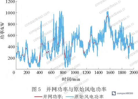
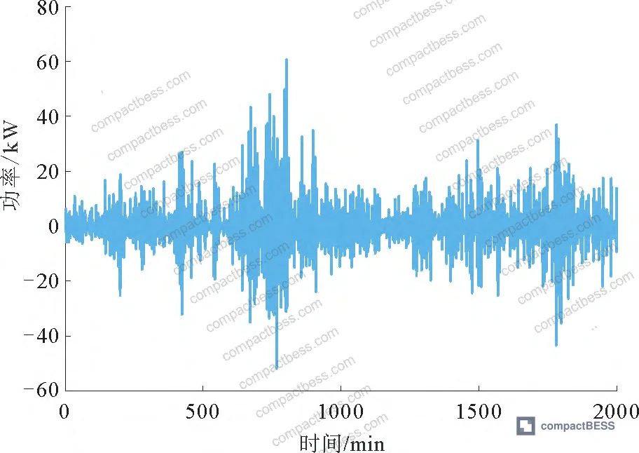
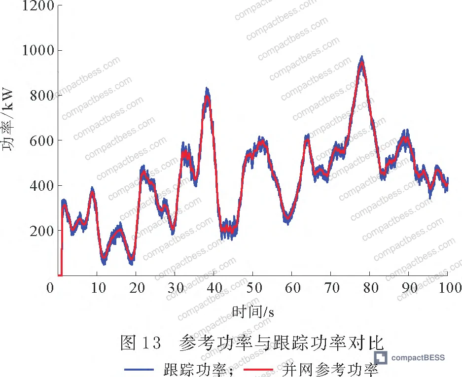
Recent simulation research conducted at a university engineering faculty in eastern China modeled a 1.5 MW wind farm scenario using 2,000 sampled data points from a northwestern China wind site, with time resolution set at 0.05-second intervals in MATLAB/Simulink. The study configured a hybrid storage bank comprising 4 lithium battery units and 4 supercapacitor units, each with distinct initial SOC values and rated capacities, and validated a two-stage power allocation strategy against real fluctuation data. The grid-connected power fluctuation limit was set at 110 kW per 10-minute window — a constraint that maps directly to real grid code requirements in several markets.
What the research confirms aligns with what we see repeatedly in supplier qualification: systems that lack adaptive SOC correction consistently fail to keep individual storage units within their safe operating window when initial SOC values are unequal across the bank. That imbalance — caused by manufacturing tolerance, aging dispersion, or installation differences — is the norm in deployed systems, not the exception. Understanding this dynamic is essential before you finalize cell format selection or compare cell chemistries for your HESS application.
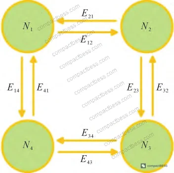
SOC Operating Boundaries in Lithium Battery Packs for Hybrid Storage #
The simulation configured four lithium battery units (LI1–LI4) with the following parameters, which reflect realistic deployed HESS configurations:
| Storage Unit | Max Power (kW) | Rated Capacity (kWh) | Initial SOC (%) | SOC Lower Limit (%) | SOC Upper Limit (%) |
|---|---|---|---|---|---|
| LI1 (Lithium) | 112 | 80 | 50.00 | 20 | 80 |
| LI2 (Lithium) | 120 | 85 | 21.50 | 20 | 80 |
| LI3 (Lithium) | 120 | 70 | 20.50 | 20 | 80 |
| LI4 (Lithium) | 112 | 70 | 20.25 | 20 | 80 |
| SC1 (Supercapacitor) | 100 | 40 | 50.00 | 10 | 90 |
| SC2 (Supercapacitor) | 110 | 45 | 10.16 | 10 | 90 |
| SC3 (Supercapacitor) | 110 | 50 | 10.13 | 10 | 90 |
| SC4 (Supercapacitor) | 110 | 40 | 10.07 | 10 | 90 |
Note the starting condition carefully: LI2, LI3, and LI4 entered operation with initial SOC values of 21.50%, 20.50%, and 20.25% respectively — all within a narrow margin of the 20% lower safety threshold. This is not a contrived test scenario. It reflects exactly the kind of state dispersion you encounter when commissioning a system with batteries from the same production batch but different storage histories.
The frequency threshold used to split the wind power signal between lithium batteries (low-frequency compensation) and supercapacitors (high-frequency response) was set at 10⁻³ Hz. Below this threshold, modal components whose grid fluctuation remained under the 110 kW limit were passed directly to the grid. Components exceeding the limit were assigned to lithium battery compensation. Everything above 10⁻³ Hz went to the supercapacitors.
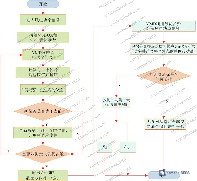
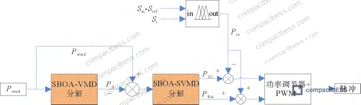
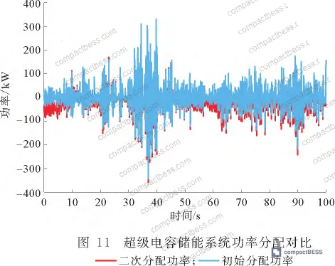
This division makes physical sense. Lithium batteries carry the slow, high-energy compensation burden. Supercapacitors absorb the fast transients. The problem arises when that initial allocation — regardless of how accurately it’s computed — doesn’t account for the fact that three of your four lithium units started near their floor.
For buyers specifying cell consistency and matching requirements for pack assembly, this data should sharpen your thinking: initial SOC spread across a battery bank is not just a commissioning issue. It’s a structural risk that the BMS architecture must address in real time.
Fuzzy Control SOC Correction and Why Primary Allocation Alone Is Not Enough #
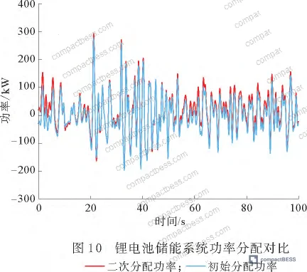
Here is where the failure story gets specific. Without secondary SOC correction, simulation results showed 3 of the 4 lithium battery groups crossed below the 20% SOC lower limit during the test period. In a real system, that triggers the BMS protection cutoff — each unit that drops out increases the load on the remaining units, accelerating their own depletion. In supplier qualification evaluations, we have seen this cascade behavior appear in field returns from HESS installations where the integrator assumed primary allocation logic was sufficient. It isn’t.
The secondary correction layer uses fuzzy logic with two inputs: the individual unit’s current SOC (Sᵢ, scaled to domain [1, 4]) and the deviation between the average battery SOC and the 50% reference SOC target (Sₘ − Sᵣₑ f, scaled to domain [−1, 1]). The output variable KSOC is scaled to domain [−2, 2] and modifies the reference power allocation for both the lithium battery group and the supercapacitor group in real time.
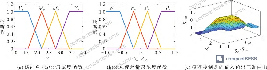
The fuzzy rule set operates on four linguistic categories per input. For individual SOC: {VS (Very Small), MS (Medium Small), MB (Medium Big), VB (Very Big)}. For the SOC deviation: {NL (Negative Large), NS (Negative Small), PS (Positive Small), PL (Positive Large)}. The control output maps these combinations to corrective adjustments that push average SOC back toward the 50% reference point.
With the secondary correction active, all four lithium battery units maintained SOC within the 20%–80% safe operating band throughout the simulation. Without it, 3 out of 4 units breached the lower limit.
Honestly, most buyers over-specify peak power capacity and under-specify the control architecture that keeps that capacity accessible. A 120 kWh lithium bank that drops out at 20% SOC because the BMS can’t dynamically rebalance load between units is effectively a 96 kWh bank with reduced cycle life. The usable capacity gap between a well-controlled and poorly controlled HESS can exceed 15–20% in real field operation.
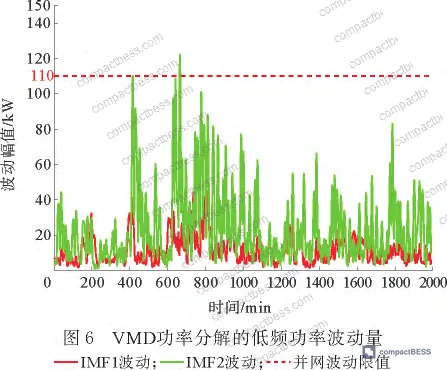
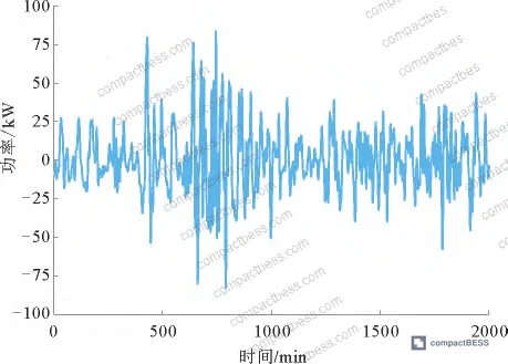
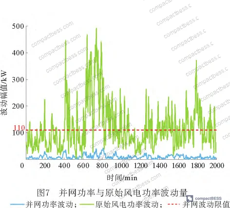
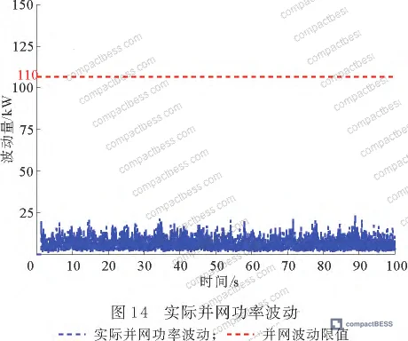
The grid output power fluctuation after the full two-stage strategy was applied remained well below the 110 kW per 10-minute threshold throughout the test window — validating that both the power quality objective and the SOC safety objective can be met simultaneously when the control architecture is properly implemented.
Signal Decomposition Parameters and Their Impact on Storage System Design #
The algorithm used to split wind power into frequency bands — Variational Mode Decomposition (VMD) optimized by the Secretary Bird Optimization Algorithm (SBOA) with 20 iterations and a population of 25 individuals — is relevant to buyers not because you’ll implement it yourself, but because it defines the control layer requirements you should be verifying in any HESS supplier’s firmware.
Most procurement teams don’t realize that the choice of frequency decomposition method has a direct material impact on battery lifetime. Low-pass filtering approaches, which remain common in lower-cost systems, assign high-frequency transient compensation to lithium batteries rather than supercapacitors — because the filter can’t resolve the boundary accurately enough. That means lithium cells are absorbing charge cycles they shouldn’t be. Over a multi-year deployment, the difference in cycle count between a VMD-based allocation and a simple low-pass filter allocation is not trivial.
The envelope entropy fitness function used to select optimal VMD parameters (minimizing the average envelope entropy across modal components) produced a frequency threshold of 10⁻³ Hz for separating lithium battery compensation from supercapacitor compensation. The SBOA algorithm required only 20 iterations with 25 population members to converge — a relatively low computational load, though the paper acknowledges that algorithm complexity may introduce latency that limits real-time applicability in the current implementation. Current deployment is primarily suited to offline or batch control scenarios.
For buyers evaluating BMS and EMS firmware in HESS products, compliance with IEC 62619:2022 Safety requirements for secondary lithium cells and batteries is a necessary baseline, but it won’t tell you whether the energy management layer is sophisticated enough to protect SOC boundaries under dynamic load. You need to ask for that separately.
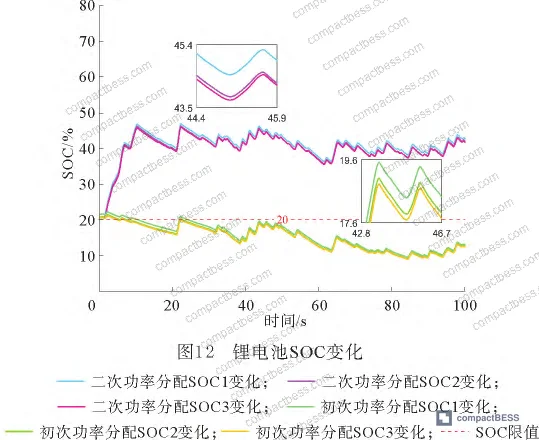
The reference SOC target of 50% is worth noting as a design parameter. Setting this midpoint gives the system equal headroom for both charging (absorbing excess wind) and discharging (compensating grid deficit). Suppliers who configure their reference SOC significantly above or below 50% are asymmetrically compromising one direction of response. Ask them why, and what their field data shows.
For deeper context on how SOC estimation accuracy feeds into these control decisions, see our documentation on SOC estimation methods.
Practical Guidance for Buyers #
If you’re sourcing lithium battery packs or integrated HESS units for wind-coupled or renewable energy applications, the test data here points to a non-obvious procurement requirement: the energy management firmware is as important as the cell chemistry or pack format.
The simulation used a 1.5 MW wind farm dataset and demonstrated that without active secondary SOC correction, three of four lithium battery units in the bank reached their lower discharge limit — a direct path to premature capacity degradation and field returns. With correction active, all units held within the 20%–80% safe band.
When you evaluate suppliers, don’t just ask for a BMS specification sheet. Ask for simulation or field data showing SOC boundary management under unequal initial SOC conditions. A technically capable supplier should be able to demonstrate this. Suppliers who can’t answer this question are working with simpler control architectures that will cost you more in service and warranty over a 5–10 year deployment.
Verify that the system’s power allocation strategy separates high-frequency transients (supercapacitor domain) from low-frequency compensation (lithium battery domain). A 10⁻³ Hz boundary is a reasonable reference point. Systems that push high-frequency loads onto lithium cells are shortening battery life systematically.
Also confirm that grid fluctuation compliance — typically expressed as a maximum rate-of-change of power per 10-minute window — is verified against the local grid code for your target market, not a generic internal spec. The 110 kW fluctuation limit used in this study maps to specific Chinese grid standards; European and North American equivalents differ.
As a Guangzhou-based B2B sourcing platform connecting global OEM buyers with verified Chinese HESS manufacturers, our team at compactbess.com has evaluated dozens of supplier firmware stacks against exactly these criteria. If you need help identifying suppliers with validated SOC management architectures, talk to our sourcing team →
Supplier Qualification Questions #
- Can you provide simulation or field test data showing the SOC trajectories of individual battery units under unequal initial SOC conditions — specifically demonstrating that no unit crosses the 20% lower limit or 80% upper limit during a 10-minute wind compensation cycle?
- What frequency threshold does your energy management system use to separate lithium battery compensation tasks from supercapacitor compensation tasks, and how was this threshold determined — is it fixed or adaptive based on real-time signal decomposition?
- In your secondary SOC correction algorithm, what is the reference SOC setpoint for lithium batteries, and how does the controller adjust per-unit charge/discharge power when the average pack SOC deviates from that reference — can you demonstrate this with logged field data?
- What is the maximum power fluctuation your system delivers to the grid per 10-minute window under a variable wind input profile equivalent to a 1.5 MW installation, and at what percentage of cycles does grid output remain below 110 kW?
- When one lithium battery unit in the bank reaches its SOC lower limit and disconnects, how does the control system redistribute compensation load to remaining units, and what is the measured impact on the SOC trajectory of those units within the following 5-minute window?
Sourcing Checklist #
- ☐ Lithium battery SOC operating range is configured with a lower limit of ≥20% and upper limit of ≤80%, verified via BMS parameter documentation or logged discharge data
- ☐ Supercapacitor SOC operating range is configured with a lower limit of ≥10% and upper limit of ≤90%, confirmed in system specification sheet
- ☐ Energy management firmware uses frequency-domain signal decomposition (VMD, wavelet, or equivalent) with a defined Hz-level boundary for separating high-frequency and low-frequency compensation tasks — not a simple low-pass filter
- ☐ Secondary SOC correction layer is present and documented, using closed-loop feedback between average pack SOC and a defined reference SOC (50% ±5% recommended), per simulation validation data
- ☐ Grid-connected power fluctuation output is verified to remain below the applicable grid code limit (e.g., 110 kW per 10-minute window for 1.5 MW installations) under variable renewable input, confirmed by test report or simulation data
- ☐ System complies with IEC 62619:2022 safety requirements for secondary lithium cells, with valid certificate from accredited third-party lab
- ☐ BMS communication protocol supports real-time SOC data broadcast to system-level EMS, verified via protocol documentation (CAN, Modbus, or equivalent)
- ☐ Transport certification per UN 38.3 is current and covers the specific cell format and pack configuration being sourced
Key Specifications Table #
| Parameter | Recommended Value | Verification Method |
|---|---|---|
| Lithium battery SOC safe operating range | 20% – 80% | BMS parameter log review; discharge cycle test to verify protection cutoff activation |
| Supercapacitor SOC safe operating range | 10% – 90% | System specification sheet; charge/discharge test under simulated load profile |
| Grid-connected power fluctuation limit | ≤110 kW per 10-minute window | Power quality analyzer data log under variable renewable input profile; compare to local grid code |
| Reference SOC setpoint for secondary correction | 50% (±5% tolerance) | EMS configuration file review; SOC trajectory log during 60-minute variable-load test |
| Frequency decomposition boundary (Li vs. SC allocation) | 10⁻³ Hz | Firmware documentation review; FFT analysis of compensation power output waveforms |
| VMD optimization algorithm convergence | ≤20 iterations, population ≥25 | Algorithm parameter documentation; convergence curve in supplier test report |
Can’t find a supplier meeting these specs? Submit your requirements and we’ll match you within 48 hours.
References #
Data source: Adaptive SOC Control Strategy for Wind-Coupled Hybrid Energy Storage Systems Using Variational Mode Decomposition and Fuzzy Logic Power Allocation, E.-R. Zheng et al., Journal of the Electrochemical Society, 2025
Frequently Asked Questions #
Why does initial SOC imbalance across battery units matter so much for hybrid storage system lifetime?
When individual battery units in a parallel or series-parallel bank start at different SOC levels — which is normal after any real-world deployment period — the unit with the lowest SOC will hit its discharge cutoff first. Once it drops out, the remaining units absorb its load share. That acceleration compounds: a three-unit bank with one disconnected unit is now running each remaining cell at 133% of its intended load, pushing them faster toward their own limits. Field data from wind storage installations confirms that this cascade effect is one of the leading causes of premature system retirement, often within 3–4 years of commissioning on systems rated for 8–10 years.
What is the practical difference between a simple low-pass filter and VMD-based power allocation for lithium battery packs?
A simple low-pass filter assigns everything below a fixed cutoff frequency to the battery bank — including mid-frequency transients that a supercapacitor could handle more efficiently. VMD adapts to the actual signal content and finds the decomposition that minimizes modal overlap, which typically results in fewer and shallower charge cycles on the lithium cells. Over a 10-year deployment with daily wind variation cycles, the difference in lithium battery cycle consumption can be significant enough to shift the pack replacement timeline by 1–2 years.
Is the 50% reference SOC target mandatory, or can it be adjusted for specific applications?
It’s a design parameter, not a fixed standard. The 50% setpoint provides symmetric headroom — equal capacity for absorbing surplus power (charging) and delivering deficit compensation (discharging). Applications with predominantly one-directional demand, such as a storage system that mostly discharges to compensate evening demand peaks, could justify a higher reference SOC like 60–65%. However, asymmetric reference SOC settings reduce the system’s ability to respond in the other direction and require careful validation against the actual load profile.
Does IEC 62619 cover the SOC management and energy dispatch logic in a HESS?
No. IEC 62619:2022 addresses safety requirements at the cell and battery level — overcharge protection, thermal management, short circuit behavior. It does not govern the energy management strategy or SOC balancing algorithms at the system level. For stationary HESS installations, IEEE 2030.2.1 covers design, operation, and maintenance practices at the system level and is a more relevant reference for evaluating control architecture quality. Procurement specs should reference both.
What grid markets require the ≤110 kW per 10-minute fluctuation constraint referenced in the research?
The specific 110 kW per 10-minute window figure used in the simulation reflects Chinese grid interconnection standards for wind power. Equivalent constraints exist in most major markets but vary: European grid codes express ramp rate limits in percent of installed capacity per minute; North American NERC standards define balancing reserve requirements differently. Before specifying a HESS control system, confirm the exact grid fluctuation limit in your target market and require the supplier to demonstrate compliance against that specific threshold — not a generic internal test value.
Published by compactbess.com Technical Team | Request a sourcing quote


