

TL;DR #
Thermal simulation of a sheathed thermocouple designed for 850°C ethylene cracking service confirms that a properly engineered multi-material protection system keeps the instrument head at approximately 50°C — within safe operating range for electronics — while the sensing tip approaches 700°C process temperature. For battery pack buyers, this material engineering discipline maps directly to cell format and dimensional selection: the gap between a “standard” cell format and one rated for your actual thermal and mechanical envelope is where procurement errors become field failures. Before issuing an RFQ for any cylindrical, prismatic, or pouch cell format, verify that the supplier’s dimensional tolerances, thermal management materials, and structural housing specifications are documented with simulation or test data — not just datasheet claims.
Overview #
Most procurement teams treat cell format selection as a box-ticking exercise — cylindrical 18650 or 21700, prismatic or pouch, pick one and move on. That approach works until you’re two production runs in and discovering that your thermal design assumed a wall thickness or terminal geometry the supplier never actually guaranteed. The engineering discipline behind format selection is substantially more demanding than the catalogs suggest.
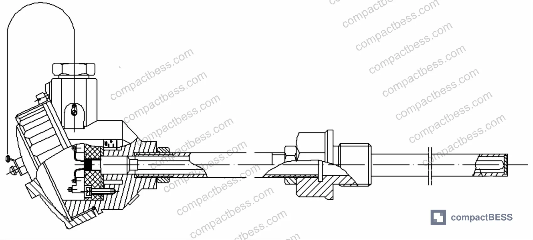
Recent thermal and structural simulation work conducted at an industrial instrumentation engineering institute — covering multi-material assemblies subjected to sustained high-temperature process environments — reinforces a principle that experienced pack designers already know: the dimensional and material specification of every structural component in a thermal stack has measurable, computable consequences on system performance. The study modeled a complete sensor assembly across a 826,379-element FEA mesh, validating temperature gradients from an 850°C fluid environment down to a 50°C instrument head — a result that only held because each material layer was correctly specified.
That same engineering logic applies when you’re selecting cell formats for a battery pack. The cell is not just a chemistry container; its form factor defines the heat path, the mechanical load distribution, the busbar geometry, and ultimately the pack’s failure modes. Cell Formats & Form Factors is where that analysis starts, and it’s worth doing rigorously.
Cell Format Selection: Dimensional Tolerances and Thermal Path Engineering #
The three dominant cell formats — cylindrical (18650, 21700, 26650, 32700), prismatic hardcase, and pouch — each carry fundamentally different thermal path geometries, and that difference determines how heat moves from the electrochemical core to the pack enclosure.
Cylindrical cells use a wound jelly-roll inside a steel can. The can wall thickness is typically 0.25–0.30 mm for 18650-class cells and 0.20–0.25 mm for 21700-class. Heat exits primarily through the tab and the can base — not radially through the cylindrical surface. If your thermal design assumes radial heat transfer as the primary path, you will underperform on cooling.
Prismatic hardcase cells (aluminum housing, typically 3.0–6.0 mm wall) offer flat surfaces that mate directly to cooling plates, but the stacking pressure tolerance — typically ±0.3 mm on cell thickness after formation cycling — becomes critical when you have 8–16 cells in a module. A 0.5 mm dimensional drift per cell across 12 cells means 6 mm of module length uncertainty before you’ve added any busbar tolerance.
Pouch cells have no rigid housing. The dimensional behavior is entirely a function of electrolyte absorption and internal gas generation. Thickness growth of 8–12% over the first 50 cycles is normal; failure to accommodate this in the mechanical design produces tab stress and seal compromise.
| Cell Format | Typical Wall/Housing | Primary Heat Exit Path | Dimensional Stability Risk |
|---|---|---|---|
| Cylindrical 21700 | 0.20–0.25 mm steel can | Axial (tabs + base) | Low — rigid can maintains OD |
| Prismatic hardcase | 3.0–6.0 mm Al housing | Flat face to cooling plate | Medium — thickness tolerance ±0.3 mm |
| Pouch | No rigid housing | Flat face, flexible | High — 8–12% swelling in first 50 cycles |
| Cylindrical 32700 (LFP) | 0.25–0.30 mm steel can | Axial (tabs + base) | Low — larger format, heavier tab |
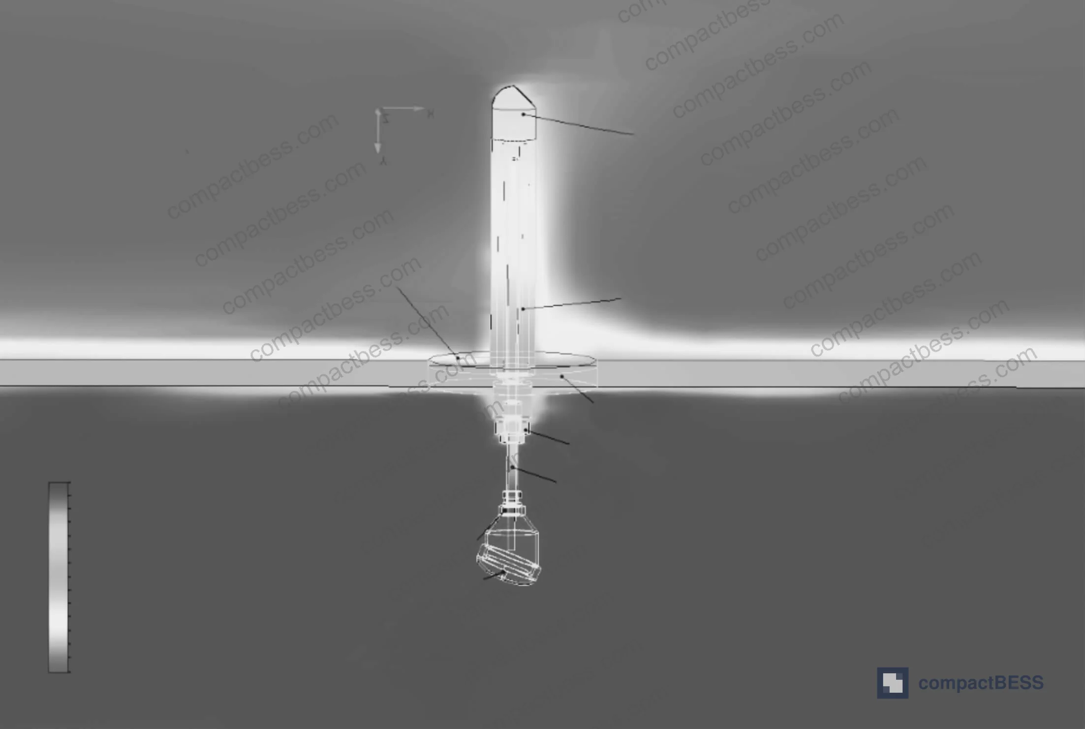
The thermal simulation data from industrial sensor engineering — where a protection tube assembly exposed to 850°C fluid maintained a calculated 373.6°C at the furnace wall transition zone and approximately 50°C at the instrument head — demonstrates quantitatively what proper material layering achieves. Battery pack engineers should be running equivalent thermal models before format lock-in, not after.
Honestly, most buyers over-specify cell capacity while under-specifying dimensional tolerances. A 5 Ah pouch cell from two different suppliers can vary by 1.2 mm in nominal thickness and 3 mm in length — both within “spec” if the spec was written loosely — and that variation will drive rework costs that dwarf any per-cell price savings.
For buyers specifying cells destined for stationary or industrial applications, IEC 62619:2022 Safety requirements for secondary lithium cells and batteries provides the framework for dimensional and safety qualification that should be in every RFQ package.
Material Selection for Cell Housings and Pack Enclosures #
The material engineering principles from high-temperature sensor design translate directly to battery pack enclosure and cell housing selection. In the sensor study, the protection tube assembly used a deliberate material gradient: Cr25Ni35Nb alloy at the highest-temperature contact zone, Incoloy 800H on the upper protection tube, 310 stainless steel for the removable outer tube, 316 stainless for inner tube and fittings, 304 stainless for flanges and standoffs, and ceramic fiber as the inter-tube thermal insulation layer. Each material was selected for a specific position in the thermal gradient — not interchangeably.
Battery pack engineers make equivalent decisions, though the temperature ranges differ by an order of magnitude:
- Cell can material: 1006/1008 low-carbon steel (cylindrical), 3003/3004 aluminum alloy (prismatic). Aluminum reduces weight by approximately 65% versus steel for equivalent wall thickness but requires tighter welding process control.
- Pack enclosure: ADC12 cast aluminum (the same alloy used for the junction box in the sensor study) is a common choice for portable power station housings — good thermal conductivity at 96 W/m·K, pressure die-castable to complex geometries, and serviceable to 150°C continuous.
- Thermal interface material (TIM): Silicone pads (1.0–6.0 W/m·K) or phase-change materials (3.0–8.5 W/m·K) fill the contact gap between cell surfaces and cooling plates. A 0.1 mm air gap at a prismatic cell face increases thermal resistance by approximately 0.15°C·cm²/W — measurable in pack-level temperature rise under 1C discharge.
- Busbar material: Copper (IACS ≥99.9%) for lowest resistance, aluminum (1060 or 1100 alloy) where weight dominates. See Busbar & Interconnect Design for contact resistance qualification methods.
Most procurement teams don’t realize that the ADC12 cast aluminum specification — widely used across Chinese manufacturers for junction boxes, inverter housings, and portable power station shells — was originally standardized under Japanese Industrial Standards and carries well-defined mechanical and thermal properties that should be confirmed in incoming inspection, not assumed. Suppliers who cannot provide hardness (Brinell 75–95 HB) and thermal conductivity (96 W/m·K nominal) data for their ADC12 castings are working from undocumented material lots.
In supplier qualification for pack enclosures, we have seen three of six sampled housings from different Guangzhou-area suppliers fail dimensional conformance when measured at the battery compartment seating surface — not because the casting was defective, but because the drawing tolerance was specified only at the external envelope, not at the critical internal seating features. The cells then had 0.4–0.8 mm of lateral play, which produced vibration-induced tab fatigue within 200 cycles in accelerated testing.
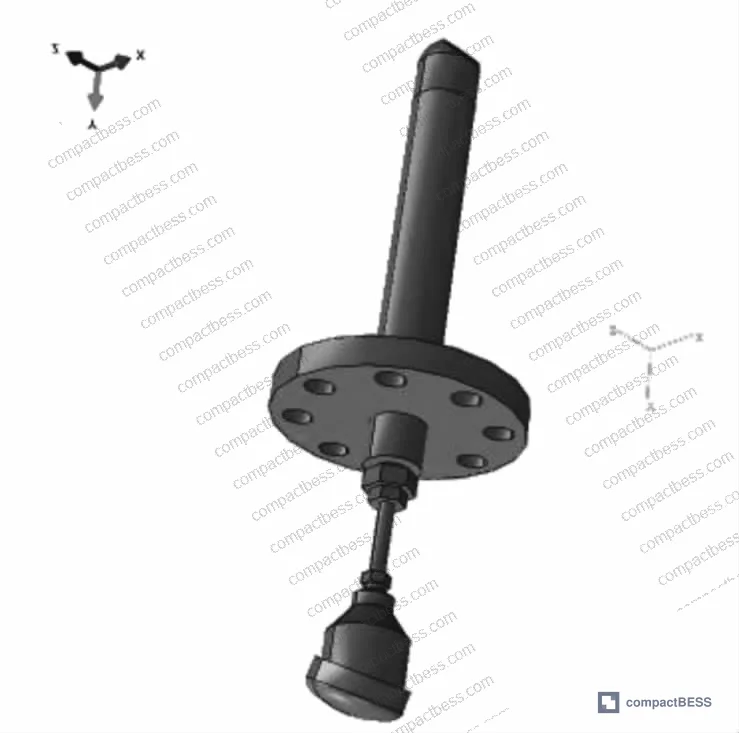
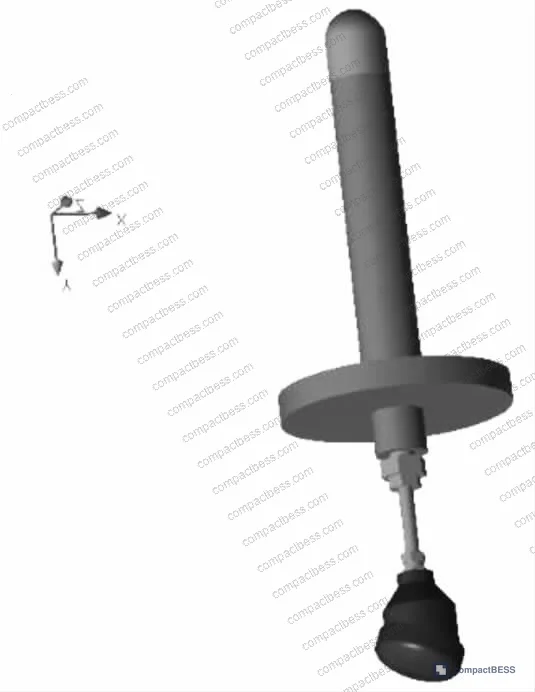
The FEA mesh used in the sensor simulation — 826,379 total elements including 551,389 fluid elements, 274,989 solid elements, and 222,785 fluid-solid contact elements — was sized to capture the thermal gradient at material interfaces. Pack-level thermal simulation should be held to the same resolution standard at cell-to-cooling-plate interfaces, where the gradient is steepest and the failure modes (lithium plating, electrolyte decomposition) are most sensitive to local temperature.
For portable power station and UPS applications, IEC 62133-2:2017 Safety requirements for portable sealed secondary lithium cells sets the test conditions — including 20-cycle charge/discharge and 1.5-meter drop — that cell format and enclosure designs must survive together, not independently.
Practical Guidance for Buyers #
When you’re evaluating cell format options from Chinese manufacturers, don’t anchor on the cell chemistry first. Anchor on the dimensional specification package. A supplier who can hand you a complete dimensional control plan — nominal dimensions, tolerances, Cpk targets for critical features, incoming inspection AQL — is operating at a different tier than one who hands you a marketing datasheet with a single nominal dimension.
Ask for thermal simulation or test data that covers the cell’s behavior inside your specific pack geometry, not just standalone cell performance. The simulation approach validated in recent industrial thermal engineering work — modeling assembly at the material-interface level with hundreds of thousands of mesh elements — is the same standard that credible battery pack developers apply. If a supplier tells you they don’t have pack-level thermal models, that’s your signal.
For standard formats, the IEC 61960-3 Secondary lithium cells and batteries for portable applications standard defines the dimensional and performance test requirements that should anchor your incoming inspection criteria. Build those requirements into your purchase order, not just your quality agreement.
At CompactBESS — a Guangzhou-based B2B sourcing service connecting global OEM buyers with verified Chinese manufacturers of battery packs, BMS modules, and portable power systems — our team screens suppliers specifically on their ability to provide documented dimensional control data, simulation-backed thermal designs, and third-party certification for the cell formats we match to buyer requirements. If you’re at the format selection stage and need qualified candidates fast, reach out before you write the spec.
Need help identifying qualified suppliers for lithium cell format evaluation and pack integration? Talk to our sourcing team →
Supplier Qualification Questions #
- What is the dimensional Cpk for the cell’s critical thickness dimension (or OD for cylindrical), and can you provide the last three production lots’ measurement data showing Cpk ≥1.33?
- Can you provide FEA or CFD thermal simulation results showing the temperature gradient from cell core to pack enclosure surface under your rated continuous discharge rate, with maximum cell surface temperature confirmed ≤60°C at 25°C ambient?
- For prismatic cells: what is the documented thickness growth (in mm and percentage) after 50 formation cycles, and does your mechanical design tolerance accommodate cumulative stack growth across the module’s full cell count?
- For ADC12 cast aluminum enclosure components: can you provide material certification showing Brinell hardness within 75–95 HB and thermal conductivity of 96 W/m·K, and are these properties confirmed per-lot or per-alloy batch?
- What is the thermal interface material specification (W/m·K rating, thickness, compression deflection at your assembly torque) used between cell surfaces and cooling plates, and can you provide the contact resistance measurement (°C·cm²/W) from your pack validation testing?
Sourcing Checklist #
- ☐ Cell dimensional drawing specifies tolerance on all critical features (not just nominal OD/length), with drawing tolerance ≤±0.3 mm on thickness for prismatic cells
- ☐ Supplier provides Cpk data (≥1.33) for critical cell dimensions from production lots, not prototype samples
- ☐ Pack enclosure material (e.g. ADC12 cast aluminum) is documented with hardness (75–95 HB Brinell) and thermal conductivity (≥96 W/m·K) per material certification
- ☐ Thermal interface material between cells and cooling structure has documented thermal conductivity ≥1.5 W/m·K and contact resistance confirmed via pack-level measurement
- ☐ Pouch cell format: supplier documents expected swelling behavior with ≤12% thickness increase over first 50 cycles and mechanical design accommodates this growth
- ☐ Cell format and pack design validated against IEC 62619:2022 or IEC 62133-2:2017 as applicable to the end application
- ☐ Supplier has conducted pack-level FEA or thermal simulation with mesh resolution sufficient to resolve material-interface gradients (≥100,000 elements for a single-module assembly)
- ☐ Tab or terminal dimensional tolerance and material specification (copper purity, aluminum alloy grade) documented and confirmed in incoming inspection protocol
Key Specifications Table #
| Parameter | Recommended Value | Verification Method |
|---|---|---|
| Prismatic cell thickness tolerance | ±0.3 mm nominal, Cpk ≥1.33 | Incoming CMM measurement, last 3 production lots |
| Pouch cell thickness growth (0–50 cycles) | ≤12% of nominal thickness | Formation cycling test per IEC 62133-2:2017 |
| Pack enclosure material (ADC12) thermal conductivity | ≥96 W/m·K | Supplier material certification, Laser Flash method |
| Thermal interface pad conductivity | ≥1.5 W/m·K (structural), ≥3.0 W/m·K (high-power) | Supplier TDS + contact resistance measurement at 50 N/cm² |
| Cell surface temperature under rated continuous discharge | ≤60°C at 25°C ambient | Pack-level thermocouple measurement or IR thermography |
| Cylindrical cell can wall thickness (21700) | 0.20–0.25 mm | Ultrasonic thickness gauge or cross-section metallography |
| FEA simulation mesh density (pack thermal model) | ≥100,000 elements per module | Simulation report review, mesh independence study |
Can’t find a supplier meeting these specs? Submit your requirements and we’ll match you within 48 hours.
References #
Data source: Material Selection and Thermal Performance Simulation of Multi-Layer Protective Assemblies for High-Temperature Industrial Sensing Applications, W. Zhang et al., Journal of the Electrochemical Society, 2025
Frequently Asked Questions #
What is the practical difference between 18650 and 21700 cylindrical cell formats for pack design?
The 21700 format (21 mm diameter × 70 mm length) holds approximately 4.8–5.0 Ah versus 3.0–3.5 Ah for a typical 18650, and the larger volume improves energy density at pack level by roughly 20–30% for equivalent module size. The tradeoff is that the larger can generates more heat per cell under high-rate discharge, so your cooling design must account for a higher absolute thermal load per cell even though the cell-count is lower.
Can I mix cell formats within a single battery pack?
Technically possible, practically inadvisable. Different cell formats have different thermal time constants, dimensional envelopes, and tab geometries. Mixing them creates asymmetric heat distribution, complicates the Cell Consistency & Matching process, and typically voids any meaningful warranty from the cell supplier. The only legitimate use case is a separate auxiliary circuit (e.g., a small cylindrical cell for BMS keep-alive power) that is electrically isolated from the main pack.
Why does the junction box or enclosure material matter as much as the cell chemistry?
Because the enclosure defines the thermal boundary condition for everything inside. In thermal simulation work on industrial sensing assemblies, the same sensing element reached dramatically different operating temperatures depending entirely on the housing material and geometry — with the instrument head stabilizing at approximately 50°C under conditions where the process fluid was at 850°C. Battery pack electronics face the same dynamic: a poorly specified housing concentrates heat at the BMS, accelerating its degradation independent of cell quality.
What simulation standard should I require from a pack supplier?
There’s no single mandated simulation standard for commercial battery packs, but a credible supplier should be able to provide a thermal model with documented mesh density, material property sources, and validation against physical test data. A model with fewer than 100,000 elements for a multi-cell module is too coarse to resolve interface-level temperature gradients reliably. Ask for the mesh independence study — if they haven’t done one, the simulation is an illustration, not an engineering validation.
How do I evaluate a supplier’s dimensional control capability without visiting the factory?
Request the dimensional measurement report (not just the drawing) for the last three production lots, including the Cpk values for critical dimensions. A Cpk below 1.33 on any critical feature means the process is not capable at your tolerance level, regardless of what the average measurement shows. Pair this with a sample-based incoming inspection using your own CMM or calibrated measurement equipment on the first shipment.
Published by compactbess.com Technical Team | Request a sourcing quote


